Page 1275 of 1399

SR16H−01
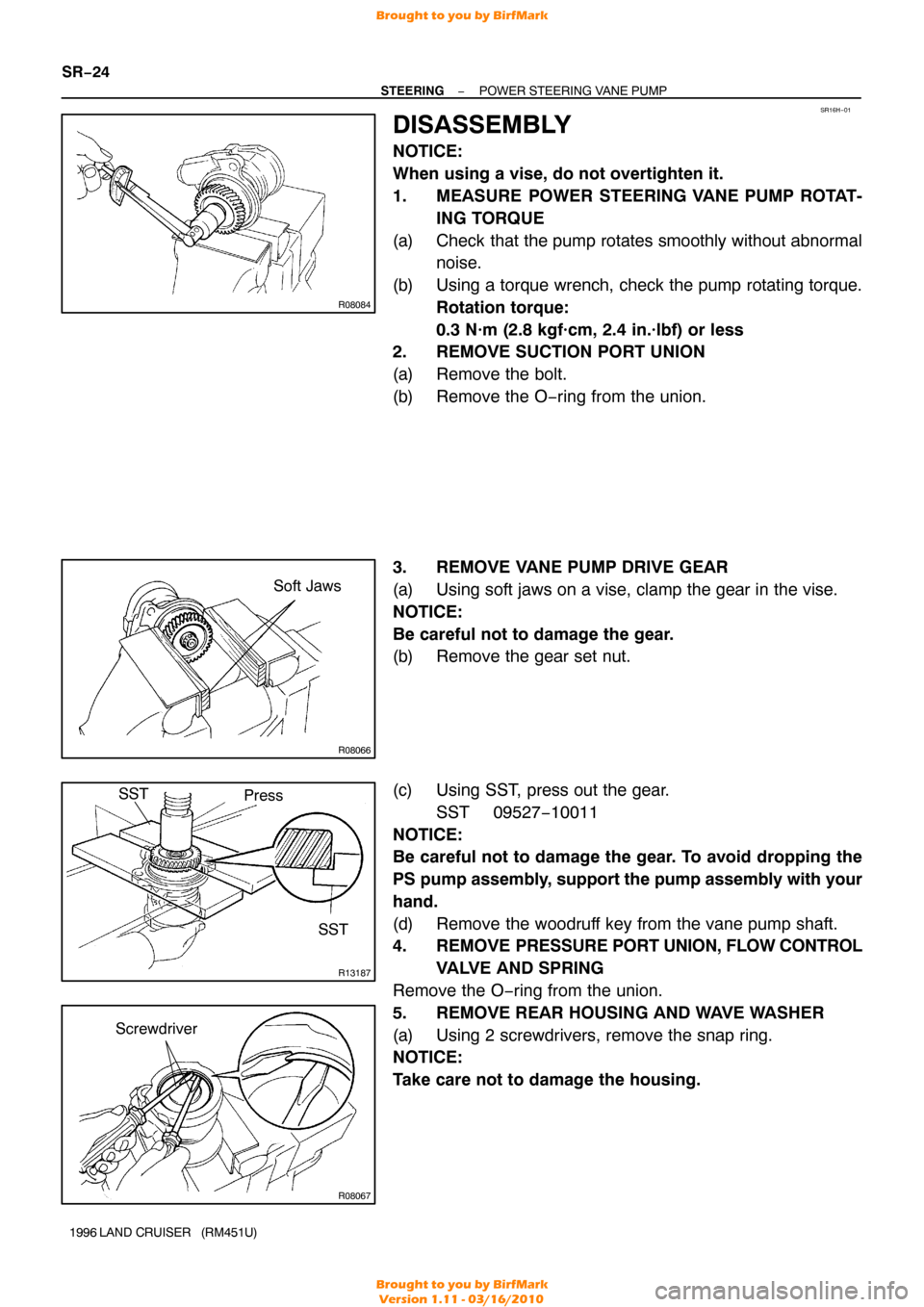
R08084
R08066
Soft Jaws
R13187
Press
SST
SST
R08067
Screwdriver
SR−24
−
STEERING POWER STEERING VANE PUMP
1996 LAND CRUISER (RM451U)
DISASSEMBLY
NOTICE:
When using a vise, do not overtighten it.
1. MEASURE POWER STEERING VANE PUMP ROTAT-
ING TORQUE
(a) Check that the pump rotates smoothly without abnormal noise.
(b) Using a torque wrench, check the pump rotating torque. Rotation torque:
0.3 N·m (2.8 kgf·cm, 2.4 in.·lbf) or less
2. REMOVE SUCTION PORT UNION
(a) Remove the bolt.
(b) Remove the O−ring from the union.
3. REMOVE VANE PUMP DRIVE GEAR
(a) Using soft jaws on a vise, clamp the gear in the vise.
NOTICE:
Be careful not to damage the gear.
(b) Remove the gear set nut.
(c) Using SST, press out the gear.
SST 09527−10011
NOTICE:
Be careful not to damage the gear. To avoid dropping the
PS pump assembly, support the pump assembly with your
hand.
(d) Remove the woodruff key from the vane pump shaft.
4. REMOVE PRESSURE PORT UNION, FLOW CONTROL
VALVE AND SPRING
Remove the O−ring from the union.
5. REMOVE REAR HOUSING AND WAVE WASHER
(a) Using 2 screwdrivers, remove the snap ring.
NOTICE:
Take care not to damage the housing.
Brought to you by BirfMark
Brought to you by BirfMark
Version 1.11 - 03/16/2010
Page 1276 of 1399

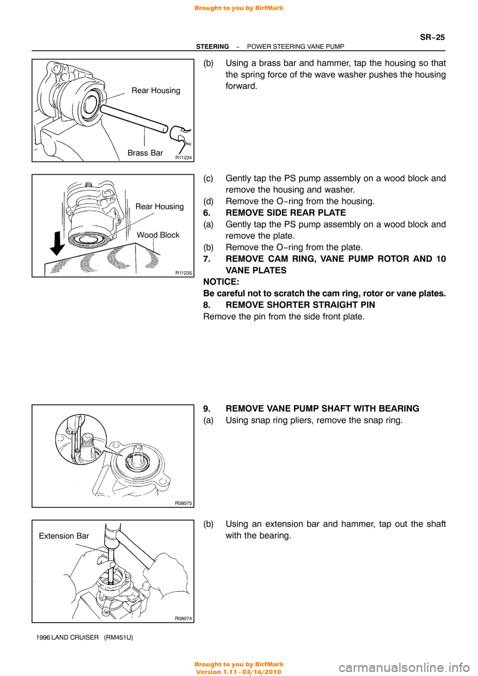
R11234
Rear Housing
Brass Bar
R11235
Rear Housing Wood Block
R08075
Extension Bar
R08074
−
STEERING POWER STEERING VANE PUMP
SR−25
1996 LAND CRUISER (RM451U)
(b) Using a brass bar and hammer, tap the housing so that
the spring force of the wave washer pushes the housing
forward.
(c) Gently tap the PS pump assembly on a wood block and remove the housing and washer.
(d) Remove the O−ring from the housing.
6. REMOVE SIDE REAR PLATE
(a) Gently tap the PS pump assembly on a wood block and remove the plate.
(b) Remove the O−ring from the plate.
7. REMOVE CAM RING, VANE PUMP ROTOR AND 10 VANE PLATES
NOTICE:
Be careful not to scratch the cam ring, rotor or vane plates.
8. REMOVE SHORTER STRAIGHT PIN
Remove the pin from the side front plate.
9. REMOVE VANE PUMP SHAFT WITH BEARING
(a) Using snap ring pliers, remove the snap ring.
(b) Using an extension bar and hammer, tap out the shaft
with the bearing.
Brought to you by BirfMark
Brought to you by BirfMark
Version 1.11 - 03/16/2010
Page 1284 of 1399

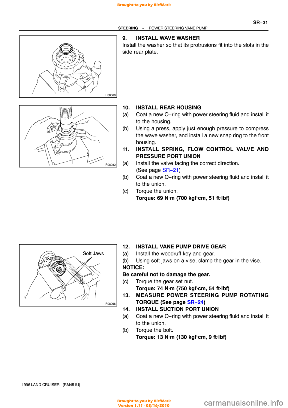
R08069
R08082
R08066
Soft Jaws
−
STEERING POWER STEERING VANE PUMP
SR−31
1996 LAND CRUISER (RM451U)
9. INSTALL WAVE WASHER
Install the washer so that its protrusions fit into the slots in the
side rear plate.
10. INSTALL REAR HOUSING
(a) Coat a new O−ring with power steering fluid and install it
to the housing.
(b) Using a press, apply just enough pressure to compress the wave washer, and install a new snap ring to the front
housing.
11. INSTALL SPRING, FLOW CONTROL VALVE AND PRESSURE PORT UNION
(a) Install the valve facing the correct direction. (See page SR−21 )
(b) Coat a new O −ring with power steering fluid and install it
to the union.
(c) Torque the union. Torque: 69 N·m (700 kgf·cm, 51 ft·lbf)
12. INSTALL VANE PUMP DRIVE GEAR
(a) Install the woodruff key and gear.
(b) Using soft jaws on a vise, clamp the gear in the vise.
NOTICE:
Be careful not to damage the gear.
(c) Torque the gear set nut. Torque: 74 N·m (750 kgf·cm, 54 ft·lbf)
13. MEASURE POWER STEERING PUMP ROTATING
TORQUE (See page SR−24 )
14. INSTALL SUCTION PORT UNION
(a) Coat a new O −ring with power steering fluid and install it
to the union.
(b) Torque the bolt.
Torque: 13 N·m (130 kgf·cm, 9 ft·lbf)
Brought to you by BirfMark
Brought to you by BirfMark
Version 1.11 - 03/16/2010
Page 1327 of 1399

SS−26
−
SERVICE SPECIFICATIONS TRANSFER
149
Author�: Date�:
1996 LAND CRUISER (RM451U)
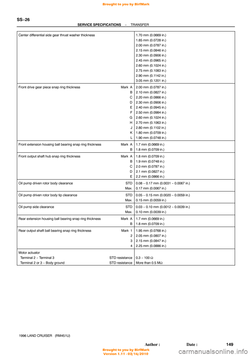
Center differential side gear thrust washer thickness
1.70 mm (0.0669 in.)
1.85 mm (0.0728 in.)
2.00 mm (0.0787 in.)
2.15 mm (0.0846 in.)
2.30 mm (0.0906 in.)
2.45 mm (0.0965 in.)
2.60 mm (0.1024 in.)
2.75 mm (0.1083 in.)
2.90 mm (0.1142 in.)
3.05 mm (0.1201 in.)
Front drive gear piece snap ring thickness
Mark A
B
C
D E
F
G H J
K
L2.00 mm (0.0787 in.)
2.10 mm (0.0827 in.)
2.20 mm (0.0866 in.)
2.30 mm (0.0906 in.)
2.40 mm (0.0945 in.)
2.50 mm (0.0984 in.)
2.60 mm (0.1024 in.)
2.70 mm (0.1063 in.)
2.80 mm (0.1102 in.)
1.80 mm (0.0709 in.)
1.90 mm (0.0748 in.)
Front extension housing ball bearing snap ring thickness Mark A
B1.7 mm (0.0669 in.)
1.8 mm (0.0709 in.)
Front output shaft hub snap ring thickness Mark A
B
C
D E1.8 mm (0.0709 in.)
1.9 mm (0.0748 in.)
2.0 mm (0.0787 in.)
2.1 mm (0.0827 in.)
2.2 mm (0.0866 in.)
Oil pump driven rotor body clearance STD
Max.0.08 − 0.17 mm (0.0031 − 0.0067 in.)
0.17 mm (0.0067 in.)
Oil pump driven rotor body tip clearance STD
Max.0.05 − 0.15 mm (0.0020 − 0.0059 in.)
0.15 mm (0.0059 in.)
Oil pump side clearance STD
Max.0.03 − 0.10 mm (0.0012 − 0.0039 in.)
0.10 mm (0.0039 in.)
Rear extension housing ball bearing snap ring thickness Mark A
B1.7 mm (0.0669 in.)
1.8 mm (0.0709 in.)
Rear output shaft ball bearing snap ring thickness Mark 1
2
3
41.95 mm (0.0768 in.)
2.05 mm (0.0807 in.)
2.15 mm (0.0847 in.)
2.25 mm (0.0886 in.)
Motor actuator
Terminal 2 − Terminal 3 STD resistance
Terminal 2 or 3 − Body ground STD resistance
0.3 − 100 Ω
More than 0.5 MΩ
Brought to you by BirfMark
Brought to you by BirfMark
Version 1.11 - 03/16/2010