Page 1106 of 1399

If the teeth are not contacting properly, use the following chart
to")
FA2041
Washer
W00529
SA2407
SST
R13140
SST
−
SUSPENSION AND AXLE FRONT DIFFERENTIAL CARRIER
SA−43
1996 LAND CRUISER (RM451U)
If the teeth are not contacting properly, use the following chart
to select a proper washer for correction.
Washer thickness
Thickness mm (in.)Thickness mm (in.)
1.70 (0.0669)2.03 (0.0799)
1.73 (0.0681)2.06 (0.0811)
1.76 (0.0693)2.09 (0.0823)
1.79 (0.0705)2.12 (0.0835)
1.82 (0.0717)2.15 (0.0846)
1.85 (0.0728)2.18 (0.0858)
1.88 (0.0740)2.21 (0.0870)
1.91 (0.0752)2.24 (0.0882)
1.94 (0.0764)2.27 (0.0894)
1.97 (0.0776)2.30 (0.0906)
2.00 (0.0787)2.33 (0.0917)
18. REMOVE COMPANION FLANGE (See page SA−29)
19. REMOVE OIL SLINGER AND REAR BEARING
20. REMOVE REAR BEARING OUTER RACE AND OIL STORAGE RING (See page SA−29 )
21. INSTALL BEARING SPACER AND REAR BEARING
(a) Install a new bearing spacer on the shaft.
(b) Install a new oil storage ring and rear bearing outer race (See page SA−29 ).
(c) Install the rear bearing and oil slinger.
22. INSTALL OIL SEAL
(a) Using SST, install a new oil seal, as shown. SST 09214−76011
Oil seal drive in depth: 1.0 mm (0.039 in.)
(b) Apply MP grease to the oil seal lip.
23. INSTALL COMPANION FLANGE
(a) Install the companion flange with SST. SST 09550 −30010 (09951 −03010, 09953 −03010,
09954 −03010, 09955 −03030, 09956−03020)
Brought to you by BirfMark
Brought to you by BirfMark
Version 1.11 - 03/16/2010
Page 1121 of 1399
SA1V0−02
R13847
SST
SA−58
−
SUSPENSION AND AXLE FRONT LEADING ARM
1996 LAND CRUISER (RM451U)
REPLACEMENT
REPLACE BUSHINGS
Using SST and a press, replace the bushing from the leading
arm. SST Front side: 09710−30050
SST Rear side: 09710 −22042 (09710−02061)
HINT:
When assembling a new bushing, as shown in the illustration.
Brought to you by BirfMark
Brought to you by BirfMark
Version 1.11 - 03/16/2010
Page 1125 of 1399
SA1V4−01
SA−62
−
SUSPENSION AND AXLE REAR AXLE SHAFT
919
Author�: Date�:
1996 LAND CRUISER (RM451U)
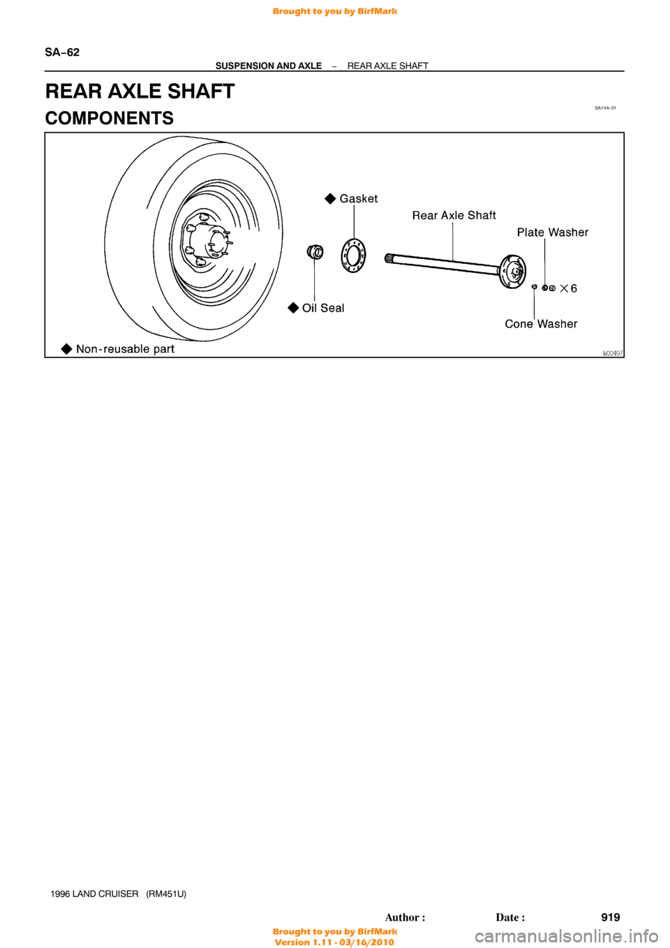
REAR AXLE SHAFT
COMPONENTS
Brought to you by BirfMark
Brought to you by BirfMark
Version 1.11 - 03/16/2010
Page 1126 of 1399
SA1V5−01
−
SUSPENSION AND AXLE REAR AXLE SHAFT
SA−63
1996 LAND CRUISER (RM451U)
REMOVAL
REMOVE REAR AXLE SHAFT
(a) Remove the 6 set nuts and plate washers.
Torque: 34 N·m (340 kgf·cm, 25 ft·lbf)
(b) Using a brass bar and hammer, strike the center part of the axle shaft to remove the 6 cone washers.
(c) Install and gradually tighten 2 bolts evenly and pull the axle shaft.
(d) Remove the 2 bolts from the rear axle shaft.
(e) Remove the rear axle shaft and gasket.
NOTICE:
Be careful not to damage the oil seal.
Brought to you by BirfMark
Brought to you by BirfMark
Version 1.11 - 03/16/2010
Page 1127 of 1399
SA1V6−01
RA0377
SA−64
−
SUSPENSION AND AXLE REAR AXLE SHAFT
1996 LAND CRUISER (RM451U)
INSPECTION
1. INSPECT REAR AXLE SHAFT
(a) Check for wear or damage.
(b) Using a dial indicator, check the runout of axle shaft. Maximum runout: 0.8 mm (0.031 in.)
If the runout is greater than the maximum, replace the axle
shaft.
2. REPLACE OIL SEAL
(a) Using SST, remove the oil seal. SST 09308−00010
(b) Using SST and a hammer, install a new oil seal into the hub.
SST 09517−36010
(c) Apply MP grease to the oil seal lip.
Brought to you by BirfMark
Brought to you by BirfMark
Version 1.11 - 03/16/2010
Page 1128 of 1399
SA1V7−02
−
SUSPENSION AND AXLE REAR AXLE SHAFT
SA−65
1996 LAND CRUISER (RM451U)
INSTALLATION
Installation is in the reverse order of removal (See page SA−63 ).
Brought to you by BirfMark
Brought to you by BirfMark
Version 1.11 - 03/16/2010
Page 1129 of 1399
SA1V8−01
SA−66
−
SUSPENSION AND AXLE REAR AXLE HUB
923
Author�: Date�:
1996 LAND CRUISER (RM451U)
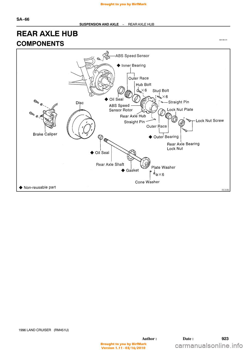
REAR AXLE HUB
COMPONENTS
Brought to you by BirfMark
Brought to you by BirfMark
Version 1.11 - 03/16/2010
Page 1130 of 1399
SA1V9−01
−
SUSPENSION AND AXLE REAR AXLE HUB
SA−67
1996 LAND CRUISER (RM451U)
REMOVAL
1. REMOVE REAR WHEEL
2. REMOVE REAR AXLE SHAFT (See page SA−63 )
3. REMOVE BRAKE CALIPER AND DISC (See page BR−34 )
4. DISCONNECT ABS SPEED SENSOR
Remove the bolt and disconnect the ABS speed sensor.
5. REMOVE REAR AXLE BEARING LOCK NUT
(a) Remove the 2 screws from the lock nut.
(b) Using SST, remove the lock nut. SST 09509−25011
6. REMOVE REAR AXLE HUB
(a) Pull out the axle hub, remove the lock nut plate and outer
bearing.
(b) Remove the axle hub.
Brought to you by BirfMark
Brought to you by BirfMark
Version 1.11 - 03/16/2010

REPLACEMENT
REPLACE BUSHINGS
Using SST and a press, replace the bushing from the leading
arm. SST")

REMOVAL
REMOVE REAR AXLE SHAFT
(a) Remove the 6 set nuts and plate washers.
Torque: 34 N·m (340 kgf·cm, 25 ft")

INSPECTION
1. INSPECT REAR AXLE SHAFT
(a) Check for wear or damage.
(b) Using a dial indicator, check th")

INSTALLATION
Installation is in the reverse order of removal (See page SA−63 ).
Brought to you by BirfMark")

REMOVAL
1. REMOVE REAR WHEEL
2. REMOVE REAR AXLE SHAFT (See page SA−63 )
3. REMOVE BRAKE CALIPER AND DISC (See")