Page 1101 of 1399

5. INSTALL SIDE BEARINGS
�w/o Differential lock:
Using SST and a press, inst")
SA2160
Boiling Water
SA2178
SA2182
SA−38
−
SUSPENSION AND AXLE FRONT DIFFERENTIAL CARRIER
1996 LAND CRUISER (RM451U)
5. INSTALL SIDE BEARINGS
�w/o Differential lock:
Using SST and a press, install the 2 side bearings on the
differential case.
SST 09950−60010 (09951 −00480)
�w/ Differential lock:
Using SST and a press, install the 2 side bearings on the
differential case.
SST 09223−15020, 09950 −60010 (09951−00480)
6. INSTALL RING GEAR ON DIFFERENTIAL CASE
(a) Clean the contact surfaces of the differential case and ring gear.
(b) Heat the ring gear to about 100° C (212°F) in boiling wa-
ter.
(c) Carefully remove the ring gear from the water.
(d) After the moisture on the ring gear has completely evapo-
rated, quickly install the ring gear to the differential case.
(e) Align the matchmarks on the ring gear and differential
case.
(f) Temporarily install new 5 lock plates and 10 set bolts.
NOTICE:
The ring gear set bolts should not tighten until the ring gear
has cooled sufficiently.
(g) After the ring gear cools down enough, tighten the set bolts uniformly and a little at a time.
Torque: 97 N·m (985 kgf·cm, 71 ft·lbf)
(h) Using a drift punch and hammer, stake the lock plates.
HINT:
Stake one claw flush with the flat surface of the bolt. For the
claw contacting the protruding portion of the bolt, stake only the
half on the tightening side.
Brought to you by BirfMark
Brought to you by BirfMark
Version 1.11 - 03/16/2010
Page 1102 of 1399

7. CHECK RING GEAR RUNOUT
(a) Install the dif")
SA2465
SA2406
SST
SA2203
SSTSST
Front
Rear
FA2042
SST
R13140
SST
−
SUSPENSION AND AXLE FRONT DIFFERENTIAL CARRIER
SA−39
1996 LAND CRUISER (RM451U)
7. CHECK RING GEAR RUNOUT
(a) Install the differential case onto the carrier and tighten the
adjusting nut just to where there is no play in the bearings.
(b) Using a dial indicator, check the ring gear runout. Maximum runout: 0.10 mm (0.0039 in.)
(c) Remove the differential case.
8. INSTALL OIL STORAGE RING
Using SST and a hammer, install a new oil storage ring. SST 09316−60011 (09316 −00011, 09316−00021)
9. INSTALL DRIVE PINION FRONT AND REAR BEARING
OUTER RACES
�Front side:
Using SST and a press, install the 2 outer races.
SST 09316−60011 (09316 −00011, 09316−00051)
�Rear side:
Using SST and a press, install the 2 outer races.
SST 09316−60011 (09316 −00011, 09316−00021)
10. INSTALL DRIVE PINION FRONT BEARING
(a) Install the plate washer on the drive pinion with the cham-
fered end facing the pinion gear.
(b) Using SST and a press, install the front bearing onto the
drive pinion.
SST 09506−30012
11. TEMPORARILY ADJUST DRIVE PINION PRELOAD
(a) Install the drive pinion, rear bearing and oil slinger.
HINT:
Assemble the spacer and oil seal after adjusting the gear con-
tact pattern.
(b) Install the companion flange with SST. SST 09550 −30010 (09951 −03010, 09953 −03010,
09954 −03010, 09955 −03030, 09956−03020)
Brought to you by BirfMark
Brought to you by BirfMark
Version 1.11 - 03/16/2010
Page 1106 of 1399

If the teeth are not contacting properly, use the following chart
to")
FA2041
Washer
W00529
SA2407
SST
R13140
SST
−
SUSPENSION AND AXLE FRONT DIFFERENTIAL CARRIER
SA−43
1996 LAND CRUISER (RM451U)
If the teeth are not contacting properly, use the following chart
to select a proper washer for correction.
Washer thickness
Thickness mm (in.)Thickness mm (in.)
1.70 (0.0669)2.03 (0.0799)
1.73 (0.0681)2.06 (0.0811)
1.76 (0.0693)2.09 (0.0823)
1.79 (0.0705)2.12 (0.0835)
1.82 (0.0717)2.15 (0.0846)
1.85 (0.0728)2.18 (0.0858)
1.88 (0.0740)2.21 (0.0870)
1.91 (0.0752)2.24 (0.0882)
1.94 (0.0764)2.27 (0.0894)
1.97 (0.0776)2.30 (0.0906)
2.00 (0.0787)2.33 (0.0917)
18. REMOVE COMPANION FLANGE (See page SA−29)
19. REMOVE OIL SLINGER AND REAR BEARING
20. REMOVE REAR BEARING OUTER RACE AND OIL STORAGE RING (See page SA−29 )
21. INSTALL BEARING SPACER AND REAR BEARING
(a) Install a new bearing spacer on the shaft.
(b) Install a new oil storage ring and rear bearing outer race (See page SA−29 ).
(c) Install the rear bearing and oil slinger.
22. INSTALL OIL SEAL
(a) Using SST, install a new oil seal, as shown. SST 09214−76011
Oil seal drive in depth: 1.0 mm (0.039 in.)
(b) Apply MP grease to the oil seal lip.
23. INSTALL COMPANION FLANGE
(a) Install the companion flange with SST. SST 09550 −30010 (09951 −03010, 09953 −03010,
09954 −03010, 09955 −03030, 09956−03020)
Brought to you by BirfMark
Brought to you by BirfMark
Version 1.11 - 03/16/2010
Page 1107 of 1399

(b) Install the plate washer and a new nut.
HINT:
Coat the threads of a new nut with g")
SA2390
SST
SA2403
SA2471
SA−44
−
SUSPENSION AND AXLE FRONT DIFFERENTIAL CARRIER
1996 LAND CRUISER (RM451U)
(b) Install the plate washer and a new nut.
HINT:
Coat the threads of a new nut with gear oil.
(c) Using SST to hold the flange, tighten the nut.
SST 09330−00021
Torque: 196 N·m (2,000 kgf·cm, 145 ft·lbf)
24. ADJUST DRIVE PINION PRELOAD
Using a torque wrench, measure the preload of the backlash
between the drive pinion and ring gear. Preload (at starting):
New bearing:
0.9 − 1.6 N·m (10 − 16 kgf·cm, 8.7 − 13.9 in.·lbf)
Reused bearing:
0.5 − 0.8 N·m (5 − 8 kgf·cm, 4.3 − 6.9 in.·lbf)
If the preload is greater than the specification, replace the bear-
ing spacer.
If the preload is less than the specification, retighten the nut a
little at a time with a torque of 13 N·m (130 kgf·cm, 9 ft·lbf) until
the specified preload is reached. Maximum torque: 343 N·m (3,500 kgf·cm, 253 ft·lbf)
If the maximum torque is exceeded while retightening the nut,
replace the bearing spacer and repeat the preload procedure.
Do not back off the pinion nut to reduce the preload.
25. RECHECK RING GEAR BACKLASH
26. RECHECK TOOTH CONTACT BETWEEN RING GEAR
AND DRIVE PINION
27. CHECK RUNOUT OF COMPANION FLANGE
28. STAKE DRIVE PINION NUT
29. INSTALL ADJUSTING NUT LOCKS
(a) Install 2 new nut locks on the bearing caps. Torque: 13 N·m (130 kgf·cm, 9 ft·lbf)
(b) After tightening bolts, bend the nut locks.
Brought to you by BirfMark
Brought to you by BirfMark
Version 1.11 - 03/16/2010
Page 1108 of 1399

Z10101
Adhesive
SA2205
SA1979Lock
−
SUSPENSION AND AXLE FRONT DIFFERENTIAL CARRIER
SA−45
1996 LAND CRUISER (RM451U)")
SA2417
Holes
Groore
Z15179
FIPG Width Approx.
1 − 2 mm (0.04 − 0.08 in.)
Z10101
Adhesive
SA2205
SA1979Lock
−
SUSPENSION AND AXLE FRONT DIFFERENTIAL CARRIER
SA−45
1996 LAND CRUISER (RM451U)
30. w/ DIFFERENTIAL LOCK:
INSTALL SHIFT FORK SHAFT
(a) Apply MP grease onto the outer circuit of the fork shaft.
(b) Install the fork shaft to match the hole of the shift fork and
that of the shift fork shaft.
(c) Remove any FIPG material and be careful not to drop oil on the contacting surface of the differential carrier and
shaft retainer.
(d) Apply FIPG to the carrier, as shown. FIPG: Part No. 08826−00090, THREE BOND 1281 or
equivalent
HINT:
Install the shaft retainer within 10 minutes after applying FIPG.
(e) Clean the threads of the bolts and retainer bolts holes with
toluene or trichlorethylene.
(f) Apply adhesive to 2 or 3 threads of the mount bolt end. Adhesive: Part No. 08833 −00080, THREE BOND 1344,
LOCTITE 242 or equivalent
(g) Tighten the shaft retainer with the 2 bolts. Torque: 24 N·m (240 kgf·cm, 17 ft·lbf)
(h) Using a pin punch and hummer, install the slotted spring pin to the shift fork.
(i) Shift the fork deeply and keep the differential lock condi- tion.
Brought to you by BirfMark
Brought to you by BirfMark
Version 1.11 - 03/16/2010
Page 1110 of 1399

5
°
108 ° 1.5 V
32
SA2306
SA1992
R08218
−
SUSPENSION AND AXLE FRONT DIFFERENTIAL CARRIER
SA−47
1996 LAND CRUISER (RM451U)
(b) Ensure that the matchmarks of the pinio")
R08154
Matchmark
(Groove)
5
°
108 ° 1.5 V
32
SA2306
SA1992
R08218
−
SUSPENSION AND AXLE FRONT DIFFERENTIAL CARRIER
SA−47
1996 LAND CRUISER (RM451U)
(b) Ensure that the matchmarks of the pinion of the actuator
is in the extent between zero and 5 degrees clockwise
above the center line of the actuator.
If the matchmarks is not in this extent, rotate the pinion to be
matched. Do not supply the battery positive voltage directly be-
tween terminals. If the matchmarks come to the extension limit
of the rotation, do not electrify moreover.
(c) Install a new O−ring to the actuator.
(d) Apply a light coat of gear oil on the O −ring.
(e) Apply MP grease to the gear part.
(f) Insert the actuator so that the long hole on the actuator side fits with the knock pin on the carrier side.
HINT:
Do not damage the O −ring of the actuator.
(g) Align the actuator with the long hole and rotate the actua-
tor counterclockwise when the knock pin reaches the
right−hand side.
(h) Install the actuator to the differential carrier with the bolt so that the outermost rack tooth of the shift fork will fit the
matchmarks of the pinion of the actuator.
Torque: 26 N·m (270 kgf·cm, 20 ft·lbf)
Brought to you by BirfMark
Brought to you by BirfMark
Version 1.11 - 03/16/2010
Page 1111 of 1399
SA1UQ−01
SA−48
−
SUSPENSION AND AXLE FRONT DIFFERENTIAL CARRIER
1996 LAND CRUISER (RM451U)
INSTALLATION
Installation is in the reverse order of removal (see page SA−27).
HINT:
�w/ differential lock:
Before installation, check differential lock operation connecting the connector of the actuator to the
connector of the vehicle side.
�w/ differential lock:
Before installation, check that the sleeves on work with switching over the differential lock control
switch.
After checking, lock the front differential.
�After installation, fill the differential with gear oil (See page SA−27).
�w/ differential lock:
After installation, check that the bleeder plug at the point of the bleeder tu\
be (inside of the engine room)
is not damaged or worn.
Brought to you by BirfMark
Brought to you by BirfMark
Version 1.11 - 03/16/2010
Page 1135 of 1399
SA1VD−01
SA−72
−
SUSPENSION AND AXLE REAR DIFFERENTIAL FRONT OIL SEAL
929
Author�: Date�:
1996 LAND CRUISER (RM451U)
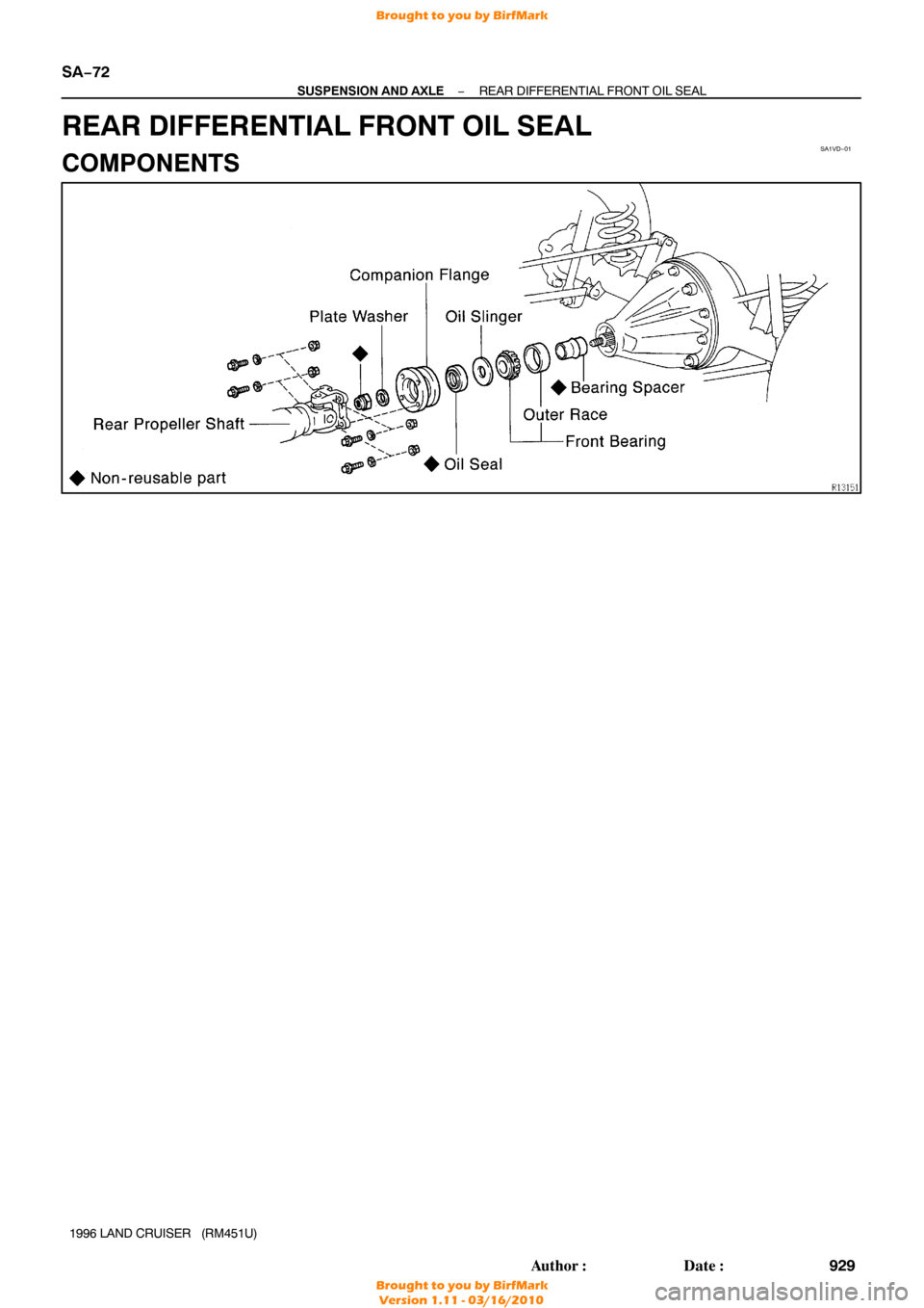
REAR DIFFERENTIAL FRONT OIL SEAL
COMPONENTS
Brought to you by BirfMark
Brought to you by BirfMark
Version 1.11 - 03/16/2010