Page 413 of 1399
P08243
SST (C)Turn
SST (A)
P03794
−
CHARGING GENERATOR
CH−11
1996 LAND CRUISER (RM451U)
(e) To loosen the pulley nut, turn SST (A) in the direction
shown in the illustration.
NOTICE:
To prevent damage to the rotor shaft, do not loosen the
pulley nut more than one −half of a turn.
(f) Remove the generator from SST (C).
(g) Turn SST (B) and remove SST (A and B).
(h) Remove the pulley nut and pulley.
6. REMOVE RECTIFIER END FRAME
(a) Remove the 4 nuts.
(b) Using SST, remove the rectifier end frame. SST 09286−46011
(c) Remove the generator washer.
7. REMOVE ROTOR FROM DRIVE END FRAME
Brought to you by BirfMark
Brought to you by BirfMark
Version 1.11 - 03/16/2010
Page 414 of 1399

CH0784
ContinuityOhmmeter
CH0HP
−01
CH0783
No Continuity Ohmmeter
CH0192
P00484
Continuity
Ohmmeter
P00482
No Continuity
Ohmmeter
CH−12
−
CHARGING GENERATOR
1996 LAND CRUISER (RM451U)
INSPECTION
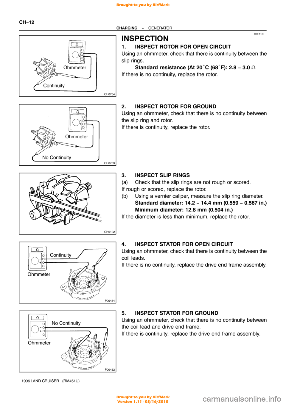
1. INSPECT ROTOR FOR OPEN CIRCUIT
Using an ohmmeter, check that there is continuity between the
slip rings.
Standard resistance (At 20 °C (68° F): 2.8 − 3.0 Ω
If there is no continuity, replace the rotor.
2. INSPECT ROTOR FOR GROUND
Using an ohmmeter, check that there is no continuity between
the slip ring and rotor.
If there is continuity, replace the rotor.
3. INSPECT SLIP RINGS
(a) Check that the slip rings are not rough or scored.
If rough or scored, replace the rotor.
(b) Using a vernier caliper, measure the slip ring diameter. Standard diameter: 14.2 − 14.4 mm (0.559 − 0.567 in.)
Minimum diameter: 12.8 mm (0.504 in.)
If the diameter is less than minimum, replace the rotor.
4. INSPECT STATOR FOR OPEN CIRCUIT
Using an ohmmeter, check that there is continuity between the
coil leads.
If there is no continuity, replace the drive end frame assembly.
5. INSPECT STATOR FOR GROUND
Using an ohmmeter, check that there is no continuity between
the coil lead and drive end frame.
If there is continuity, replace the drive end frame assembly.
Brought to you by BirfMark
Brought to you by BirfMark
Version 1.11 - 03/16/2010
Page 415 of 1399

P13535
Length
Z04143
Positive (+)
Terminal
Rectifier
Terminal
Ohmmeter
Z04144
Negative (− )
Terminal
Ohmmeter
P00644
CH1026
−
CHARGING GENERATOR
CH−13
1996 LAND CRUISER (RM451U)
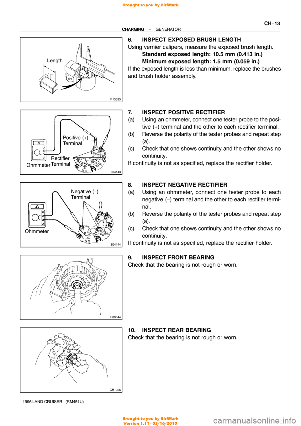
6. INSPECT EXPOSED BRUSH LENGTH
Using vernier calipers, measure the exposed brush length.
Standard exposed length: 10.5 mm (0.413 in.)
Minimum exposed length: 1.5 mm (0.059 in.)
If the exposed length is less than minimum, replace the brushes
and brush holder assembly.
7. INSPECT POSITIVE RECTIFIER
(a) Using an ohmmeter, connect one tester probe to the posi- tive (+) terminal and the other to each rectifier terminal.
(b) Reverse the polarity of the tester probes and repeat step (a).
(c) Check that one shows continuity and the other shows no
continuity.
If continuity is not as specified, replace the rectifier holder.
8. INSPECT NEGATIVE RECTIFIER
(a) Using an ohmmeter, connect one tester probe to each negative ( −) terminal and the other to each rectifier termi-
nal.
(b) Reverse the polarity of the tester probes and repeat step
(a).
(c) Check that one shows continuity and the other shows no continuity.
If continuity is not as specified, replace the rectifier holder.
9. INSPECT FRONT BEARING
Check that the bearing is not rough or worn.
10. INSPECT REAR BEARING
Check that the bearing is not rough or worn.
Brought to you by BirfMark
Brought to you by BirfMark
Version 1.11 - 03/16/2010
Page 418 of 1399
P03802
CH06M−03
P03794
P03807
Hold SST (A)
SST (B)
Turn
P08242
SST (C)
CH−16
−
CHARGING GENERATOR
1996 LAND CRUISER (RM451U)
REASSEMBLY
1. PLACE RECTIFIER END FRAME ON PULLEY
2. INSTALL ROTOR TO DRIVE END FRAME
3. INSTALL RECTIFIER END FRAME
(a) Place the generator washer on the rotor.
(b) Using a 29 mm socket wrench and press, slowly press in
the rectifier end frame.
(c) Install the 4 nuts. Torque: 4.5 N·m (46 kgf·cm, 40 in.·lbf)
4. INSTALL PULLEY
(a) Install the pulley to the rotor shaft by tightening the pulley
nut by hand.
(b) Hold SST (A) with a torque wrench, and tighten SST (B)
clockwise to the specified torque.
SST 09820−63010
Torque: 39 N·m (400 kgf·cm, 29 ft·lbf)
(c) Check that SST (A) is secured to the pulley shaft.
(d) Mount SST (C) in a vise.
(e) Install the generator to SST (C).
Brought to you by BirfMark
Brought to you by BirfMark
Version 1.11 - 03/16/2010
Page 419 of 1399
P08244
SST (A)
SST (C)
Turn
−
CHARGING GENERATOR
CH−17
1996 LAND CRUISER (RM451U)
(f) To torque the pulley nut turn SST (A) in the direction
shown in the illustration.
Torque: 110.5 N·m (1,128 kgf·cm, 81 ft·lbf)
(g) Remove the generator from SST (C).
(h) Turn SST (B), and remove SST (A and B).
5. INSTALL RECTIFIER HOLDER
(a) Place the seal plate on the rectifier end frame.
(b) Install the 4 rubber insulators on the lead wires.
(c) Install the rectifier holder with the 4 screws. Torque: 2.9 N·m (30 kgf·cm, 25 in.·lbf)
6. INSTALL VOLTAGE REGULATOR
Install the voltage regulator on the rectifier end frame with the
3 screws. Torque: 2.0 N·m (20 kgf·cm, 17 in.·lbf)
Brought to you by BirfMark
Brought to you by BirfMark
Version 1.11 - 03/16/2010
Page 420 of 1399
CH−18
−
CHARGING GENERATOR
1996 LAND CRUISER (RM451U)
7. INSTALL BRUSH HOLDER
(a) Install the brush holder on the rectifier end frame with the
2 screws.
NOTICE:
Be careful of the holder installation direction. Torque: 2.0 N·m (20 kgf·cm, 17 in.·lbf)
(b) Place the brush holder cover on the brush holder.
8. INSTALL REAR END COVER
(a) Install the end cover together with the rectifier plate. (1) Hand tighten the bolt first for positioning the plate.
(2) Tighten the 3 nuts and bolt.
Torque:
Bolt: 3.8 N·m (39 kgf·cm, 34 in.·lbf)
Nut: 4.4 N·m (45 kgf·cm, 39 in.·lbf)
(b) Install the terminal insulator with the nut. Torque: 4.1 N·m (42 kgf·cm, 36 in.·lbf)
9. CHECK THAT ROTOR ROTATES SMOOTHLY
Brought to you by BirfMark
Brought to you by BirfMark
Version 1.11 - 03/16/2010
Page 421 of 1399
CH06N−03
−
CHARGING GENERATOR
CH−19
1996 LAND CRUISER (RM451U)
INSTALLATION
1. INSTALL GENERATOR
(a) Mount generator on the generator bracket with the pivot
bolt. Do not tighten the bolt yet.
(b) Install the drive belt adjusting bar with the bolt and nut. Torque: 21 N·m (210 kgf·cm, 15 ft·lbf)
(c) Temporarily install the lock bolt.
(d) Connect the generator connector.
(e) Connect the generator wire with the nut and rubber cap.
(f) Connect the generator wire clamp to the generator.
2. INSTALL DRIVE BELTS
(a) Install the drive belts.
(b) Adjust the drive belt with the adjusting bolt (See page
CH−2 ).
(c) Tighten the pivot and adjusting lock bolts. Torque:
Pivot bolt: 59 N·m (600 kgf·cm, 43 ft·lbf)
Lock bolt: 21 N·m (210 kgf·cm, 15 ft·lbf)
3. CONNECT POWER STEERING (PS) RESERVOIR TANK
4. INSTALL BATTERY TRAY AND BATTERY
5. PERFORM ON−VEHICLE INSPECTION (See page CH−2 )
Brought to you by BirfMark
Brought to you by BirfMark
Version 1.11 - 03/16/2010
Page 422 of 1399
CO0IO−04
−
COOLING COOLANT
CO−1
696
Author�: Date�:
1996 LAND CRUISER (RM451U)
COOLANT
INSPECTION
HINT:
Check the coolant level when the engine is cold.
1. CHECK ENGINE COOLANT LEVEL AT RADIATOR RESERVOIR
The engine coolant level should be between the ”LOW” and ”FULL”\
lines.
If low, check for leaks and add engine coolant up to the ”FULL” line.
2. CHECK ENGINE COOLANT QUALITY
(a) Remove the radiator cap.
CAUTION:
To avoid the danger of being burned, do not remove the radiator cap while the engine and radiator
are still hot, as fluid and steam can be blown out under pressure.
(b) There should not be any excessive deposits of rust or scale around the r\
adiator cap or radiator filler
hole, and the coolant should be free from oil.
If excessively dirty, replace the coolant.
(c) Reinstall the radiator cap.
Brought to you by BirfMark
Brought to you by BirfMark
Version 1.11 - 03/16/2010