Page 1318 of 1399
SS1EY−03
−
SERVICE SPECIFICATIONS IGNITION
SS−17
140
Author�: Date�:
1996 LAND CRUISER (RM451U)
IGNITION
SERVICE DATA
Firing order−1 − 5 − 3 − 6 − 2 − 4
High −tension cordResistance Maximum25 kΩ per cord
Spark plugRecommended spark plug ND
NGK
Correct electrode gapK16R−U
BKR5EYA
0.8 mm (0.031 in.)
Ignition coilPrimary coil resistance at cold
at hot
Secondary coil resistance at cold
at hot0.36 − 0.55 Ω
0.45 − 0.65 Ω
9.0 − 15.4 kΩ
11.4 − 18.1 kΩ
DistributorAir gap
Pickup coil resistance at cold (G1 − G�)
(G2 − G�)
(NE − G�)
at hot (G1 − G� )
(G2 − G�)
(NE − G�)0.2 − 0.4 mm (0.008 − 0.016 in.)
185 − 275 Ω
185 − 275 Ω
185 − 275 Ω
240 − 325 Ω
240 − 325 Ω
240 − 325 Ω
Crankshaft
position sensorResistance at cold (NE� − NE� )
at hot (NE� − NE� )1,630 − 2,740 Ω
2,065 − 3,225 Ω
Brought to you by BirfMark
Brought to you by BirfMark
Version 1.11 - 03/16/2010
Page 1319 of 1399
SS1EZ−01
SS−18
−
SERVICE SPECIFICATIONS IGNITION
1996 LAND CRUISER (RM451U)
TORQUE SPECIFICATION
Part tightenedN·mkgf·cmft·lbf
Spark plug x Cylinder head2020014
Distributor x Cylinder head1818013
Crankshaft position sensor protector x No. 1 oil pan2020014
Crankshaft position sensor x No. 1 oil pan99078 in.·lbf
Brought to you by BirfMark
Brought to you by BirfMark
Version 1.11 - 03/16/2010
Page 1324 of 1399

AUTOMATIC TRANSMISSION
SERVICE DATA
Line pressure (Wheel locked)
Engine idling")
SS1E6−02
−
SERVICE SPECIFICATIONS AUTOMATIC TRANSMISSION
SS−23
146
Author�: Date�:
1996 LAND CRUISER (RM451U)
AUTOMATIC TRANSMISSION
SERVICE DATA
Line pressure (Wheel locked)
Engine idling D position R position
AT stall (Throttle valve fully opened) D position R position
422 − 481 kPa (4.3 − 4.9 kgf/cm2, 61 − 70 psi)
510 − 608 kPa (5.2 − 6.2 kgf/cm2, 74 − 88 psi)
1,285 − 1,530 kPa (13.1 − 15.6 kgf/cm2, 128 − 153 psi)
1,579 − 1,932 kPa (16.1 − 19.7 kgf/cm2, 158 − 193 psi)
Engine stall revolution D and R position1,950 ± 150 rpm
Time lag N → D position
N → R positionLess than 1.2 seconds
Less than 1.5 seconds
Engine idle speed (A/C OFF) N position650 ± 50 rpm
Throttle cable adjustment (throttle valve fully closed)
Between boot and face and inner cable stopper
0 −1 mm (0 − 0.04 in.)
Torque converter clutch installation distance
Drive plate runout Max.
Torque converter clutch runout Max.More than 15.7 mm (0.618 in.)
0.20 mm (0.0079 in.)
0.30 mm (0.0118 in.)
Shift point
D position
Throttle valve fully opened 1 → 2
2 → 3
3 → O/D
O/D → 3
3 → 2
2 → 1
2 position
Throttle valve fully opened 3 → 2
L position
Throttle valve fully opened 2 → 1
56 − 62 km/h (35 − 39 mph)
103 − 114 km/h (64 − 71 mph)
152 − 163 km/h (94 − 101 mph)
145 − 156 km/h (90 − 97 mph)
95 − 101 km/h (59 − 63 mph)
42 − 47 km/h (26 − 29 mph)
116 − 127 km/h (72 − 79 mph)
56 − 62 km/h (38 − 39 mph)
Lock−up point Throttle valve opening 5 %
D position Lock −up ON
Lock− up OFF
77 − 83 km/h (48 − 52 mph)
68 − 74 km/h (42 − 46 mph)
Brought to you by BirfMark
Brought to you by BirfMark
Version 1.11 - 03/16/2010
Page 1325 of 1399

TORQUE SPECIFICATION
Part tightenedN·mkgf·cmft·lbf
Valve body x Transmission case101007
Oil staine")
SS1E7−01
SS−24
−
SERVICE SPECIFICATIONS AUTOMATIC TRANSMISSION
1996 LAND CRUISER (RM451U)
TORQUE SPECIFICATION
Part tightenedN·mkgf·cmft·lbf
Valve body x Transmission case101007
Oil stainer x Valve body101007
Oil pan7.47565 in.·lbf
Drain plug x Oil pan2020515
Parking lock pawl bracket x Transmission case7.47565 in.·lbf
Front propeller shaft x Front dif ferential7475054
Front propeller shaft x Transfer7475054
Rear propeller shaft x Transfer8890065
Rear propeller shaft x Rear dif ferential8890065
Drive plate x Crankshaft981,00072
Torque converter clutch x Drive plate5555040
Front exhaust pipe x Exhaust manifold6263046
Front exhaust pipe x TWC3940029
Oil cooler pipe3435025
Transmission x Engine7173053
Exhaust pipe clamp1919514
Park/neutral position switch Nut
Bolt6.9 1370
13061 in.·lbf 9
No. 2 vehicle speed sensor5.45548 in.·lbf
Speedometer driven gear sleeve x Locking plate1616012
Starter mounting bolt3940029
Transfer shift lever1818513
Stabilizer bar bracket mounting bolt1818513
Engine under cover mounting bolt2829021
Exhaust pipe No. 1 support bracket x Torque converter clutch housing2424017
Crossmember x Frame6162045
Engine rear mounting x Crossmember7475054
Transmission shift lever assembly x Body5.45548 in.·lbf
Oil cooler mounting bolt1111 58
Brought to you by BirfMark
Brought to you by BirfMark
Version 1.11 - 03/16/2010
Page 1328 of 1399
SS1E9−02
−
SERVICE SPECIFICATIONS TRANSFER
SS−27
1996 LAND CRUISER (RM451U)
TORQUE SPECIFICATION
Part tightenedN·mkgf·cmft·lbf
Oil pump plate and separator x Rear extension housing4.95043 in.·lbf
Oil pump cover x Rear extension housing4.95043 in.·lbf
Lever lock pin121209
Oil strainer x Rear case4.95043 in.·lbf
Oil receiver x Front case121209
Case cover x Rear case3738027
Rear extension housing x Rear case3738027
Front extension housing x Front case3738027
Center differential lock Indicator switch3738014
L4 position switch3738027
Neutral position switch3738027
Screw plug x Front case1919014
Screw plug x Rear extension housing2930022
Motor actuator x Front case1818513
Differential front case x Differential rear case
Temporarily tighten98
881,00090072
65
Front case x Rear case3738027
Rear case x Retainer3940028
Dynamic damper x Rear extension housing3738027
Brought to you by BirfMark
Brought to you by BirfMark
Version 1.11 - 03/16/2010
Page 1341 of 1399

BODY ELECTRICAL
SERVICE DATA
TURN SIGNAL FLASHER
Flashes/Minute60 − 120
SPEEDOMETER")
SS1EJ−02
SS−40
−
SERVICE SPECIFICATIONS BODY ELECTRICAL
163
Author�: Date�:
1996 LAND CRUISER (RM451U)
BODY ELECTRICAL
SERVICE DATA
TURN SIGNAL FLASHER
Flashes/Minute60 − 120
SPEEDOMETER (USING A SPEEDOMETER)
Standard indication (mph)Allowable range (mph)
2018 − 24
4038 − 44
6058 − 66
8078 − 88
10098 − 11 0
12011 8 − 132
TACHOMETER (ON− VEHICLE) DC 13.5 V 25°C (77° F)
Standard indication (RPM)Allowable range (RPM)
700630 − 770
1,000900 − 1,100
2,0001,875 − 2,125
3,0002,850 − 3,150
4,0003,850 − 4,150
5,0004,850 − 5,150
FUEL RECEIVER GAUGE
A − B85.5 − 105.5 Ω
A − C126 − 150 Ω
B − C90 − 110 Ω
FUEL SENDER GAUGE
Float position F: Approx. 15 mm ((0.59 in.)Approx. 3 Ω
Float position E: Approx. 200 (7.87 in.)Approx. 110 Ω
ENGINE COOLANT TEMPERATURE RECEIVER GAUGE
A − B71 − 79 Ω
A − C117 − 141 Ω
B − C185 − 215 Ω
OIL PRESSURE RECEIVER GAUGE
Resistance40 − 48 Ω
CRUISE CONTROL SWITCH
Switch position OFFNo continuity
Switch position RESUME/ACCELApprox. 68 Ω
Switch position SET/COASTApprox. 198 Ω
Switch position CANCELApprox. 418 Ω
CRUISE CONTROL ACTUATOR
1 − 3Approx. 2 kΩ
2 − 3Approx. 0.5 − 1.7 kΩ
Actuator control arm free play0 mm (0 in.)
Brought to you by BirfMark
Brought to you by BirfMark
Version 1.11 - 03/16/2010
Page 1364 of 1399
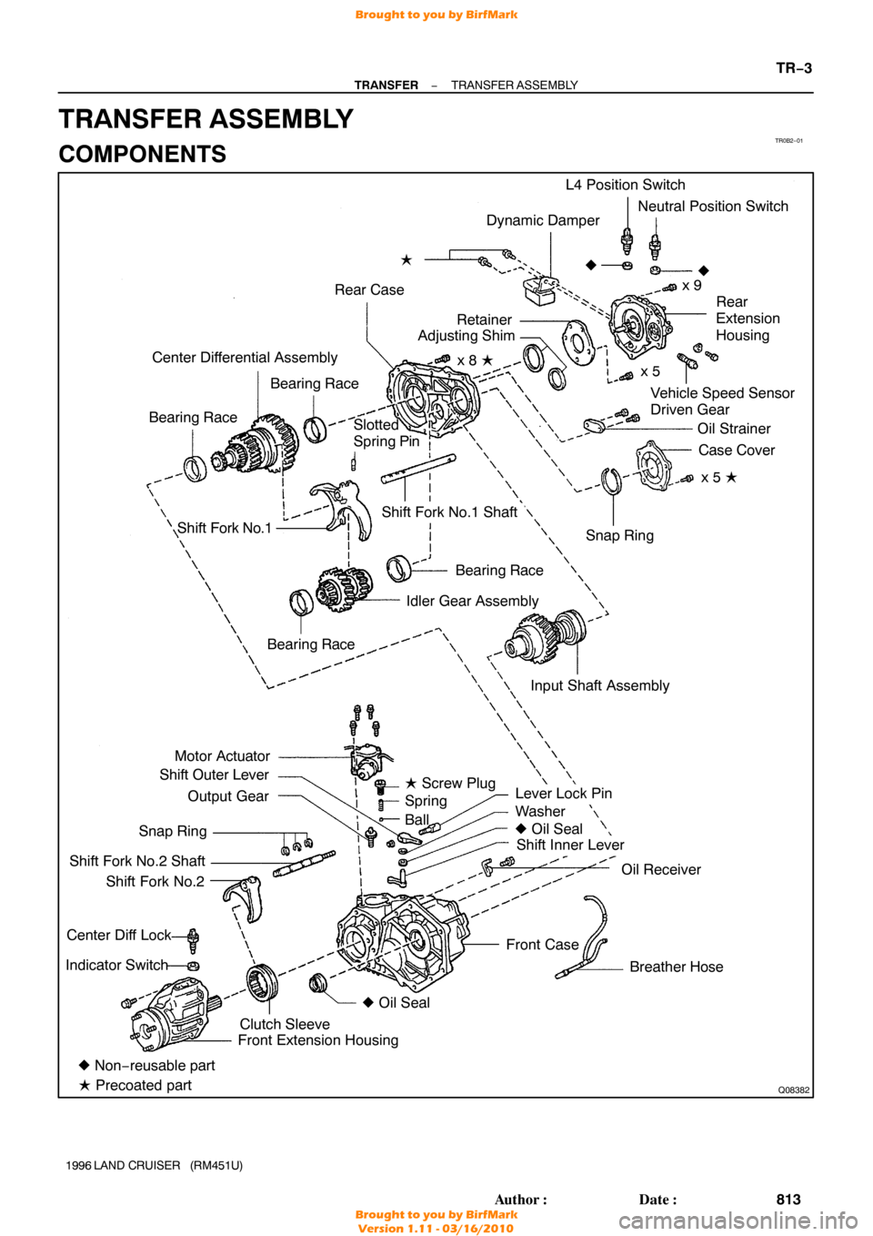
TR0B2−01
Q08382
Dynamic Damper
Rear Case �
Vehicle Speed Sensor
Driven Gear
Center Differential Assembly
Bearing Race
Bearing Race L4 Position Switch
Neutral Position Switch
x 9
�
Rear
Extension
Housing
Oil Strainer Case Cover
x 5 �
Shift Fork No.1
Bearing Race
Idler Gear Assembly
Motor Actuator
Shift Outer Lever
Output Gear
Snap Ring
Shift Fork No.2 Shaft Shift Fork No.2
Center Diff Lock
Indicator Switch
Lever Lock Pin
Washer
� Oil Seal
Shift Inner Lever
Oil Receiver
Breather Hose
Front Case Snap Ring
Shift Fork No.1 Shaft
� Non− reusable part
� Precoated part Front Extension Housing
Clutch Sleeve �
Oil Seal
Bearing Race
�
Slotted
Spring Pin
Input Shaft Assemblyx 5
x 8 �
Retainer
Adjusting Shim
� Screw Plug
Spring
Ball
−
TRANSFER TRANSFER ASSEMBLY
TR−3
813
Author�: Date�:
1996 LAND CRUISER (RM451U)
TRANSFER ASSEMBLY
COMPONENTS
Brought to you by BirfMark
Brought to you by BirfMark
Version 1.11 - 03/16/2010
Page 1366 of 1399

6. REMOVE TRANSFER INDICATOR SWITCH
Remove the Center Diff Lock indicator switch, L4 position")
Q04610
Q00541
Front
Q02950
Q07125
FIPG
−
TRANSFER TRANSFER ASSEMBLY
TR−5
1996 LAND CRUISER (RM451U)
6. REMOVE TRANSFER INDICATOR SWITCH
Remove the Center Diff Lock indicator switch, L4 position
switch, Neutral position switch and 3 gaskets.
Torque: 37 N·m (380 kgf·cm, 27 ft·lbf)
7. REMOVE FRONT EXTENSION HOUSING
Remove the 6 bolts and front extension housing.
HINT:
If necessary, tap the front extension housing with a plastic ham-
mer.
HINT:
At the time of reassembly, please refer to the following items.
�Set the clutch sleeve in differential lock condition.
�Apply FIPG to the front case.
FIPG: Part No. 08826−00090, THREE BOND 1281 or
equivalent
Torque: 37 N·m (380 kgf·cm, 27 ft·lbf)
8. REMOVE CLUTCH SLEEVE, SHIFT FORK NO.2 SHAFT AND SHIFT FORK NO.2
HINT:
At the time of reassebly, make sure to install the clutch sleeve
in the correct direction.
9. SEPARATE SHIFT FORK NO.2 SHAFT AND SHIFT FORK NO.2
(a) Using 2 screwdrivers and a hammer, tap out the 3 snap rings from the shift fork No.2 shaft.
(b) Separate the shift fork No.2 shaft and shift fork No.2.
10. REMOVE REAR EXTENSION HOUSING
Remove the 9 bolts and rear extension housing.
HINT:
If necessary, tap the rear extension housing with a plastic ham-
mer.
HINT:
At the time of reassembly, apply FIPG to the rear case. FIPG: Part No. 08826−00090, THREE BOND 1281 or
equivalent
Torque: 37 N·m (380 kgf·cm, 27 ft·lbf)
Brought to you by BirfMark
Brought to you by BirfMark
Version 1.11 - 03/16/2010


TORQUE SPECIFICATION
Part tightenedN·mkgf·cmft·lbf
Spark plug x Cylinder head2020014
Distributor x Cylinder head")

TORQUE SPECIFICATION
Part tightenedN·mkgf·cmft·lbf
Oil pump plate and separator x Rear extension housing4.95043 i")