Page 1219 of 1399
−
SFI INJECTOR
SF−33
1996 LAND CRUISER (RM451U)
(k) Connect the 6 injector connectors as shown.
2. INSTALL FUEL INLET PIPE
Install the fuel inlet pipe with 4 new gaskets, the 2 union bolts
and bolt.
Torque:
Union bolt: 29 N·m (300 kgf·cm, 22 ft·lbf)
Bolt: 20 N·m (200 kgf·cm, 14 ft·lbf)
3. INSTALL FUEL RETURN PIPE
(a) Install the fuel return pipe with the 2 bolts. Torque: 20 N·m (200 kgf·cm, 14 ft·lbf)
(b) Connect the fuel hose to the fuel pressure regulator.
4. INSTALL AIR INTAKE CHAMBER
Install 2 new gaskets and the air intake chamber with the 6 bolts
and 2 nuts. Torque: 21 N·m (210 kgf·cm, 15 ft·lbf)
5. CONNECT NO.1 WATER BYPASS HOSE TO CYL- INDER HEAD
6. CONNECT VACUUM HOSES TO TVV
Brought to you by BirfMark
Brought to you by BirfMark
Version 1.11 - 03/16/2010
Page 1222 of 1399
SF0OZ−12
SF−36
−
SFI FUEL TANK AND LINE
664
Author�: Date�:
1996 LAND CRUISER (RM451U)
FUEL TANK AND LINE
COMPONENTS
CAUTION:
�Always use new gaskets when replacing the fuel tank or component parts.
�Apply the proper torque to all parts tightened.
Brought to you by BirfMark
Brought to you by BirfMark
Version 1.11 - 03/16/2010
Page 1223 of 1399
BO0919
Z00085
FU0041
SF0P0−06
−
SFI FUEL TANK AND LINE
SF−37
1996 LAND CRUISER (RM451U)
INSPECTION
INSPECT FUEL TANK AND LINE
(a) Check the fuel lines for cracks or leakage, and all connec-
tions for deformation.
(b) Check the fuel tank vapor vent system hoses and connec-
tions for looseness, sharp bends or damage.
(c) Check the fuel tank for deformation, cracks fuel leakage
or tank band looseness.
(d) Check the filler neck for damage or fuel leakage.
(e) Hose and tube connections are as shown in the illustra- tion.
If a problem is found, repair or replace the part as necessary.
Brought to you by BirfMark
Brought to you by BirfMark
Version 1.11 - 03/16/2010
Page 1243 of 1399

SF1F7−01
P09134
OhmmeterContinuity
Ohmmeter Ohmmeter
Continuity
No Continuity FP
PR
FPR
+B1
+B2
P09135
Ohmmeter
No
Continuity
Battery
Ohmmeter
Continuity +B1
+B2 FP
PR
FPR
−
SFI FUEL PUMP RELAY
SF−57
685
Author�: Date�:
1996 LAND CRUISER (RM451U)
FUEL PUMP RELAY
INSPECTION
1. REMOVE FUEL PUMP RELAY
(a) Disconnect the fuel pump relay connector.
(b) Remove the bolt and fuel pump relay.
2. INSPECT FUEL PUMP RELAY CONTINUITY
(a) Using an ohmmeter, check that there is continuity be-
tween terminals +B1 and FPR.
(b) Check that there is continuity between terminals +B2 and
FP.
(c) Check that there is no continuity between terminals +B2
and PR.
If continuity is not as specified, replace the relay.
3. INSPECT FUEL PUMP RELAY OPERATION
(a) Apply battery voltage across terminals +B1 and FPR.
(b) Using an ohmmeter, check that there is no continuity be- tween the +B2 and FP.
(c) Check that there is continuity between terminals +B2 and
PR.
If operation is not as specified, replace the relay.
4. REINSTALL FUEL PUMP RELAY
Brought to you by BirfMark
Brought to you by BirfMark
Version 1.11 - 03/16/2010
Page 1244 of 1399
SF1F8−01
SF−58
−
SFI FUEL PUMP RESISTOR
686
Author�: Date�:
1996 LAND CRUISER (RM451U)
FUEL PUMP RESISTOR
INSPECTION
1. REMOVE FUEL PUMP RESISTOR
(a) Disconnect the fuel pump resistor connector.
(b) Remove the bolt and fuel pump resistor.
2. INSPECT FUEL PUMP RESISTOR
Using an ohmmeter, measure the resistance between the ter-
minals.
Resistance: 0.70 − 0.76 Ω at 20°C (68°F)
If there is no continuity, replace the resistor.
3. REINSTALL FUEL PUMP RESISTOR Torque: 18 N·m (185 kgf·cm, 13 ft·lbf)
Brought to you by BirfMark
Brought to you by BirfMark
Version 1.11 - 03/16/2010
Page 1245 of 1399
SF1F9−01
−
SFI VSV FOR FUEL PRESSURE CONTROL
SF−59
687
Author�: Date�:
1996 LAND CRUISER (RM451U)
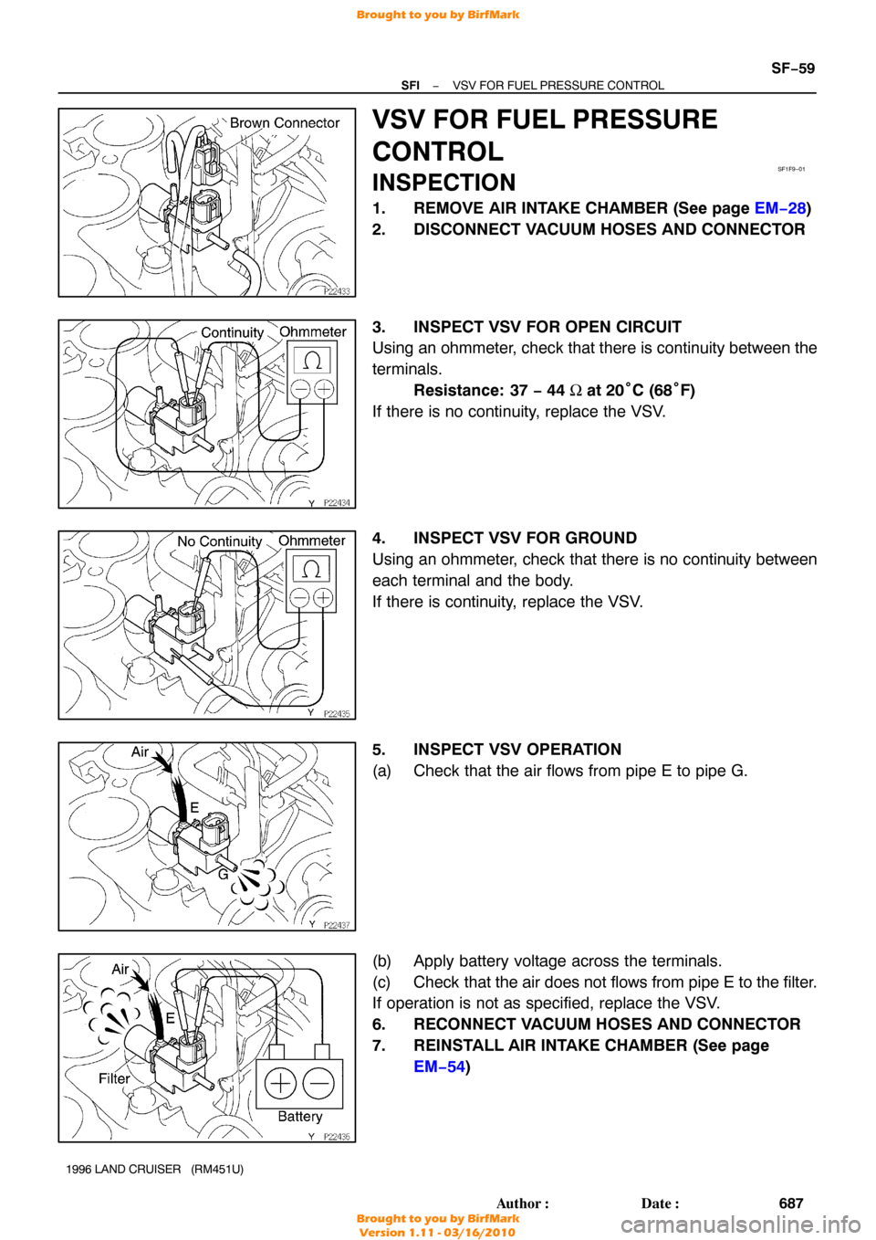
VSV FOR FUEL PRESSURE
CONTROL
INSPECTION
1. REMOVE AIR INTAKE CHAMBER (See page EM−28 )
2. DISCONNECT VACUUM HOSES AND CONNECTOR
3. INSPECT VSV FOR OPEN CIRCUIT
Using an ohmmeter, check that there is continuity between the
terminals. Resistance: 37 − 44 Ω at 20° C (68°F)
If there is no continuity, replace the VSV.
4. INSPECT VSV FOR GROUND
Using an ohmmeter, check that there is no continuity between
each terminal and the body.
If there is continuity, replace the VSV.
5. INSPECT VSV OPERATION
(a) Check that the air flows from pipe E to pipe G.
(b) Apply battery voltage across the terminals.
(c) Check that the air does not flows from pipe E to the filter.
If operation is not as specified, replace the VSV.
6. RECONNECT VACUUM HOSES AND CONNECTOR
7. REINSTALL AIR INTAKE CHAMBER (See page EM−54 )
Brought to you by BirfMark
Brought to you by BirfMark
Version 1.11 - 03/16/2010
Page 1253 of 1399
SF0Q2−08
−
SFI FUEL CUT RPM
SF−67
695
Author�: Date�:
1996 LAND CRUISER (RM451U)
FUEL CUT RPM
INSPECTION
1. WARM UP ENGINE
Allow the engine to warm up to normal operating temperature.
2. CONNECT TOYOTA HAND −HELD TESTER OR OBD II
SCAN TOOL
(a) Remove the fuse cover on the instrument panel.
(b) Connect the TOYOTA hand−held tester or OBD II scan tool to the DLC3.
(c) Please refer to the TOYOTA hand−held tester or OBD II
scan tool operator’s manual for further details.
3. INSPECT FUEL CUTOFF PRM
(a) Increase the engine speed to at least 3,500 rpm.
(b) Use a sound scope to check for injector operating noise.
(c) Check that when the throttle lever is released, injector op-
eration noise stops momentarily and then resumes.
HINT:
Measure with the A/C OFF. Fuel return rpm: 1,200 rpm
4. DISCONNECT TOYOTA HAND −HELD TESTER OR
OBD II SCAN TOOL
Brought to you by BirfMark
Brought to you by BirfMark
Version 1.11 - 03/16/2010
Page 1263 of 1399

3. REMOVE INSTRUMENT LOWER FINISH PANEL
(a) Disconnect the hood lock control cable and fuel lid control
cable.
(b) Remove the 4")
SR−12
−
STEERING TILT STEERING COLUMN
1996 LAND CRUISER (RM451U)
3. REMOVE INSTRUMENT LOWER FINISH PANEL
(a) Disconnect the hood lock control cable and fuel lid control
cable.
(b) Remove the 4 panel set screws.
4. REMOVE NO.2 HEATER TO REGISTER DUCT
5. REMOVE UPPER AND LOWER COLUMN COVERS
Remove the 5 screws.
6. REMOVE COMBINATION SWITCH WITH SPIRAL CABLE
(a) Disconnect the 2 connectors.
(b) Disconnect the airbag connector.
(c) Remove the 4 screws.
NOTICE:
Do not disassemble the cable or apply oil to it.
7. REMOVE 4 COLUMN HOLE COVER SET BOLTS
8. REMOVE LINK JOINT PROTECTOR
Remove the 2 bolts.
9. DISCONNECT SLIDING YOKE SUB−ASSEMBLY
(a) Place matchmarks on the yoke sub −assembly and worm
gear valve body shaft.
(b) Loosen bolt A and remove bolt B.
10. REMOVE SLIDING YOKE SUB−ASSEMBLY
Remove the bolt A.
11. REMOVE TILT STEERING COLUMN ASSEMBLY
(a) Disconnect the 3 connectors.
(b) Remove the 2 column assembly set nuts and 2 set bolts.
Brought to you by BirfMark
Brought to you by BirfMark
Version 1.11 - 03/16/2010

(k) Connect the 6 injector connectors as shown.
2. INSTALL FUEL INLET PIPE
Install the fuel inlet pipe with 4 new gaskets, the 2 union bolts
and")


INSPECTION
INSPECT FUEL TANK AND LINE
(a) Check the fuel lines for cracks or leakage, and all connec-
t")