Page 1334 of 1399

TORQUE SPECIFICATION
Part tightenedN·mkgf·cmft·lbf
FRONT
Axle hub x Disc6465047
Axle hub bearing lock")
SS1ED−02
−
SERVICE SPECIFICATIONS SUSPENSION AND AXLE
SS−33
1996 LAND CRUISER (RM451U)
TORQUE SPECIFICATION
Part tightenedN·mkgf·cmft·lbf
FRONT
Axle hub x Disc6465047
Axle hub bearing lock nut6465047
Flange x Axle hub3536026
Brake caliper x Axle carrier1231,25090
Brake caliper x Flexible hose3031022
Steering knuckle x Knuckle arm9698071
Bearing cap x Steering knuckle9698071
Knuckle arm x Tie rod9192567
Steering knuckle x Knuckle spindle4747534
Oil seal end retainer x Knuckle arm5.45548 in.·lbf
ABS speed sensor set bolt x Steering knuckle1818513
Hub nut Steel wheel
Aluminum wheel147
1031,500
1,050109 76
Drain plug4950036
Filler plug4950036
Propeller shaft x Companion flange8890065
Side bearing cap x Differential carrier7880058
Ring gear x Differential case9798571
Drive pinion x Companion flange196 − 3432,000 − 3,500145 − 253
Differential LH case x RH case4748035
Differential lock shift retainer2424017
Differential lock screw plug2222016
Differential lock indicator switch4041030
Differential lock actuator2627020
Differential carrier x Axle housing2728020
Adjusting nut lock x Bearing cap131309
Follow spring x Frame9.29482 in.·lbf
Stabilizer bar x Axle housing2526019
Shock absorber x Axle housing6970051
Shock absorber x Frame6970051
Stabilizer bar link x Cover1818513
Stabilizer bar link x Link bracket1031,05076
Lateral control rod x Frame1711,750127
Lateral control rod x Axle housing1711,750127
Leading arm x Frame1771,800130
Leading arm x Axle housing1711,750127
REAR
Rear axle shaft x Axle hub3434025
Rear axle bearing lock nut5960043
Rear axle bearing lock nut screw5.45548 in.·lbf
Brke caliper x Axle carrier1031,05076
ABS speed sensor set bolt1818513
Brought to you by BirfMark
Brought to you by BirfMark
Version 1.11 - 03/16/2010
Page 1337 of 1399

TORQUE SPECIFICATION
Part tightenedN·mkgf·cmft·lbf
Master cylinder x Piston stopper bolt101007
Master cylinder x Re")
SS1EF−02
SS−36
−
SERVICE SPECIFICATIONS BRAKE
1996 LAND CRUISER (RM451U)
TORQUE SPECIFICATION
Part tightenedN·mkgf·cmft·lbf
Master cylinder x Piston stopper bolt101007
Master cylinder x Reservoir1.717.515.2 in.·lbf
Master cylinder x Brake booster131309
Brake line union nut1515511
Brake booster clevis lock nut2526019
Brake booster x Pedal bracket131309
Bleeder plug1111 08
Front disc brake caliper installation bolt1231,25090
Front disc brake caliper x Flexible hose3031022
Parking brake bellcrank x Backing plate131309
Rear disc brake cliper x Spindle pin8890065
Rear disc brake caliper x Flexible hose3031022
Rear disc brake torque plate x Knuckle1031,05076
LSP & BV bracket x Frame2526019
LSP & BV x LSP & BV bracket131309
LSP & BV spring x LSP & BV bracket1818513
LSP & BV spring x Shackle No. 11818513
LSP & BV shackle lock nut2525018
LSP & BV shackle x Shackle bracket131309
LSP & BV shackle bracket x Rear axle housing1919514
ABS actuator assembly x Body1919514
ABS actuator x Actuator bracket5.45548 in.·lbf
ABS control relay x Actuator bracket131309
Front speed sensor installation bolt1818513
Rear speed sensor installation bolt1818513
Brought to you by BirfMark
Brought to you by BirfMark
Version 1.11 - 03/16/2010
Page 1364 of 1399
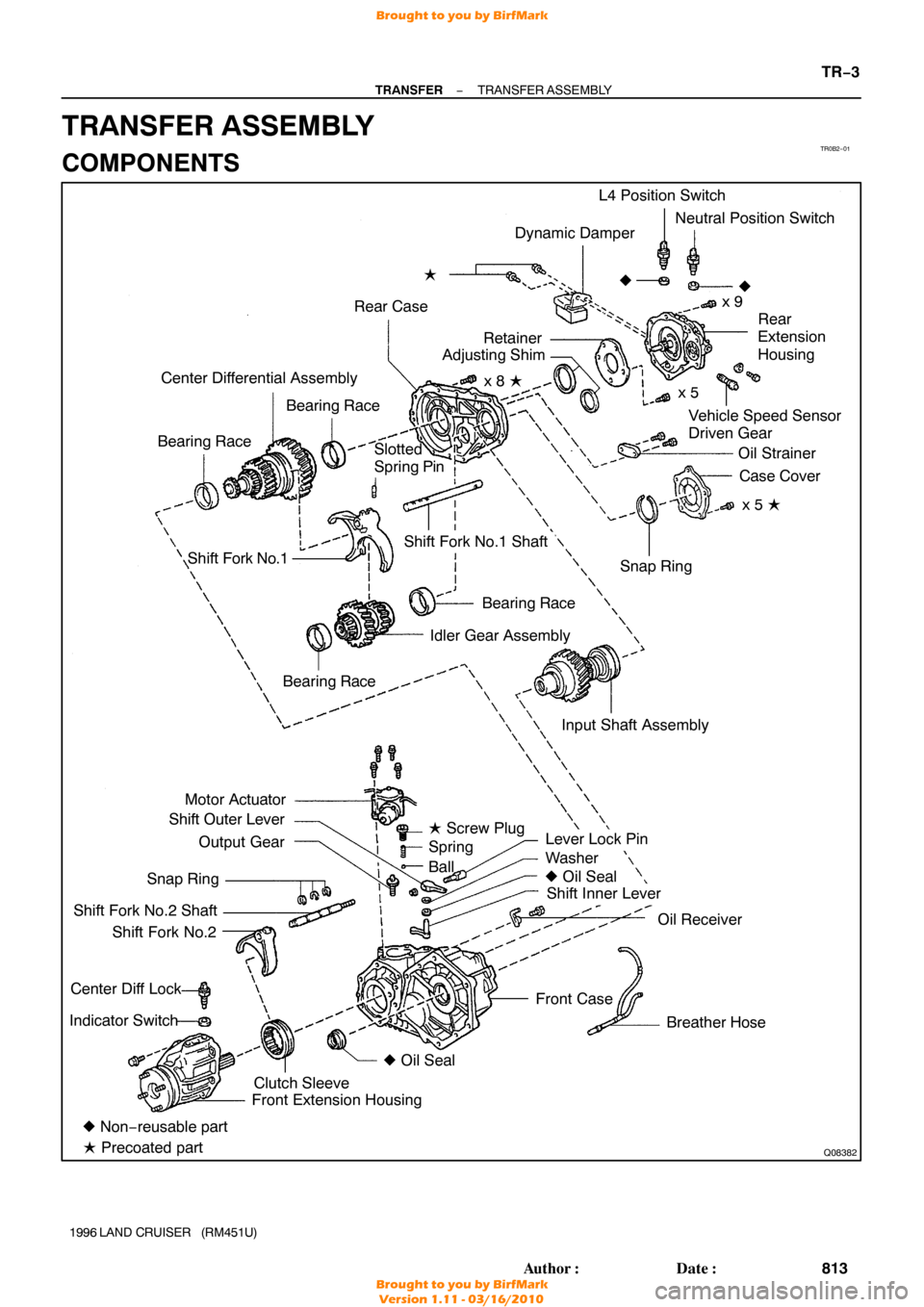
TR0B2−01
Q08382
Dynamic Damper
Rear Case �
Vehicle Speed Sensor
Driven Gear
Center Differential Assembly
Bearing Race
Bearing Race L4 Position Switch
Neutral Position Switch
x 9
�
Rear
Extension
Housing
Oil Strainer Case Cover
x 5 �
Shift Fork No.1
Bearing Race
Idler Gear Assembly
Motor Actuator
Shift Outer Lever
Output Gear
Snap Ring
Shift Fork No.2 Shaft Shift Fork No.2
Center Diff Lock
Indicator Switch
Lever Lock Pin
Washer
� Oil Seal
Shift Inner Lever
Oil Receiver
Breather Hose
Front Case Snap Ring
Shift Fork No.1 Shaft
� Non− reusable part
� Precoated part Front Extension Housing
Clutch Sleeve �
Oil Seal
Bearing Race
�
Slotted
Spring Pin
Input Shaft Assemblyx 5
x 8 �
Retainer
Adjusting Shim
� Screw Plug
Spring
Ball
−
TRANSFER TRANSFER ASSEMBLY
TR−3
813
Author�: Date�:
1996 LAND CRUISER (RM451U)
TRANSFER ASSEMBLY
COMPONENTS
Brought to you by BirfMark
Brought to you by BirfMark
Version 1.11 - 03/16/2010
Page 1390 of 1399
TR0BH−01
Q08383
Center Differential Control
Couping Assembly
Snap ring Vehicle Speed sensor
Drive Gear Ball Bearing
� Snap Ring
Snap Ring
Oil Pump Plate
Drive Rotor
Oil Pump Cover
Rear Extension housing
Oil Pump Drive Shaft Ball
Spring �
Screw Plug
Valve Seat
�
Dust Deflector
� Oil Seal Seal Ring
Rear Output Shaft
� Non− reusable Part
� Precoated part Separator
Driven Rotor
−
TRANSFER REAR EXTENSION HOUSING
TR−29
839
Author�: Date�:
1996 LAND CRUISER (RM451U)
REAR EXTENSION HOUSING
COMPONENTS
Brought to you by BirfMark
Brought to you by BirfMark
Version 1.11 - 03/16/2010
Page 1391 of 1399

DISASSEMBLY
1. REMOVE OIL PUMP DRIVE SHAFT
2. REMOVE OIL PUMP COVER
(a) Using a torx soc")
TR0BI−01
Q00530
Q08384
Q02549
Q07138
TR−30
−
TRANSFER REAR EXTENSION HOUSING
1996 LAND CRUISER (RM451U)
DISASSEMBLY
1. REMOVE OIL PUMP DRIVE SHAFT
2. REMOVE OIL PUMP COVER
(a) Using a torx socket wrench (T30), remove the 3 screws.
(b) Install the 2 suitable bolts to the pump cover.
(c) Remove the pump cover from the rear extension housing.
3. REMOVE DRIVE ROTOR FROM DRIVEN ROTOR
4. REMOVE DRIVEN ROTOR FROM REAR EXTENSION HOUSING
5. REMOVE SCREW PLUG, SPRING, BALL AND VALVE SEAT
(a) Using a hexagon wrench, remove the screw plug.
(b) Using a magnetic finger, remove the spring, ball and valve
seat from the rear extension housing.
6. REMOVE CENTER DIFFERENTIAL CONTROL COU- PLING ASSEMBLY
(a) Using a snap ring expander, remove the snap ring.
(b) Remove the coupling assembly from the rear extension housing.
7. REMOVE SEPARATOR AND OIL PUMP PLATE
Remove the 3 bolts, separator and oil pump plate.
8. REMOVE VEHICLE SPEED SENSOR DRIVE GEAR
(a) Using a snap ring expander, remove the snap ring.
(b) Remove the vehicle speed sensor drive gear.
Brought to you by BirfMark
Brought to you by BirfMark
Version 1.11 - 03/16/2010
Page 1395 of 1399

4. INSTALL REAR OUTPUT SHAFT
(a) Using SST and a press, install the rear output shaft.")
TF0969
SST
TF0958
Q07138
Q02549
Q08384
TR−34
−
TRANSFER REAR EXTENSION HOUSING
1996 LAND CRUISER (RM451U)
4. INSTALL REAR OUTPUT SHAFT
(a) Using SST and a press, install the rear output shaft.
SST 09316−20011, 09316 −60011 (09316−00011,
09316 −00031)
(b) Install the 2 seal rings to the rear output shaft.
(c) Select a snap ring that will allow minimum axial play.
MarkThickness mm (in.)
11.95 (0.0768)
22.05 (0.0807)
32.15 (0.0847)
42.25 (0.0886)
(d) Using a snap ring expander, install a new snap ring.
5. INSTALL VEHICLE SPEED SENSOR DRIVE GEAR
(a) Install the vehicle speed sensor drive gear.
(b) Using a snap ring expander, install the snap ring.
6. INSTALL OIL PUMP PLATE AND SEPARATOR
(a) Install the oil pump plate.
(b) Install the separator.
(c) Install and torque the 3 bolts. Torque: 4.9 N·m (50 kgf·cm, 43 in.·lbf)
7. INSTALL CENTER DIFFERENTIAL CONTROL COU- PLING ASSEMBLY
(a) Install the coupling assembly to the output shaft.
(b) Using a snap ring expander, install the snap ring.
8. INSTALL VALVE SEAT, BALL, SPRING AND SCREW PLUG
(a) Apply gear oil to the ball.
(b) Install the valve seat, ball and spring.
(c) Apply liquid sealer to the screw plug.
Sealant: Part No. 08833−00080, THREE BOND 1344,
LOCTITE 242 or equivalent
(d) Using a hexagon wrench, install and torque the screw plug.
Torque: 29 N·m (300 kgf·cm, 22 ft·lbf)
Brought to you by BirfMark
Brought to you by BirfMark
Version 1.11 - 03/16/2010