Page 1131 of 1399

REPLACEMENT
1. REMOVE OIL SEAL AND INNER BEARING
(a) Using SST, rem")
SA1VA−01
R13157
Brass Bar
Positions
R13158
SST
R13159
SA−68
−
SUSPENSION AND AXLE REAR AXLE HUB
1996 LAND CRUISER (RM451U)
REPLACEMENT
1. REMOVE OIL SEAL AND INNER BEARING
(a) Using SST, remove the oil seal.
SST 09308−00010
(b) Remove the inner bearing from the hub.
2. REMOVE BEARING OUTER RACE
Using a brass bar and hammer, remove the bearing outer
races.
NOTICE:
Be careful not to damage the ABS speed sensor rotor.
3. INSTALL BEARING OUTER RACE
�Outside race:
Using SST and a press, install new bearing outer races.
SST 09950−60020 (09951 −00710),
09950 −70010 (09951 −07150)
�Inside race:
Using SST and a press, install new bearing outer races.
SST 09950−60020 (09951 −00810),
09950 −70010 (09951 −07150)
4. PACK BEARINGS WITH MP GREASE
(a) Place MP grease on the palm of your hand.
(b) Pack grease into the bearing until the grease ooze out from the other side.
(c) Do the same around the bearing circumference.
5. COAT INSIDE OF HUB WITH MP GREASE
6. INSTALL INNER BEARING AND OIL SEAL
(a) Place inner bearing into the hub.
(b) Using SST, install a new oil seal into the hub. SST 09223−15020, 09950 −70010 (09951−07150)
(c) Apply MP grease to the oil seal lip.
Brought to you by BirfMark
Brought to you by BirfMark
Version 1.11 - 03/16/2010
Page 1133 of 1399
W00498
OK
−0.2 − 0.9 mm
SA−70
−
SUSPENSION AND AXLE REAR AXLE HUB
1996 LAND CRUISER (RM451U)
(g) Check the distance between top surface of axle housing
and the lock nut.
Standard distance:
−0.2 − 0.9 mm (−0.0079 − 0.0354 in.)
If the distance is greater than the specification, reassemble the
lock nut plate.
(h) Check that the hub with disc rotates smoothly and hub has no axial play.
5. INSTALL BEARING LOCK NUT SCREW
Tighten the 2 lock nut screws. Torque: 5.4 N·m (55 kgf·cm, 48 in.·lbf)
6. CONNECT ABS SPEED SENSOR
Connect the ABS speed sensor install the bolt.
Torque: 18 N·m (185 kgf·cm, 13 ft·lbf)
7. INSTALL BRAKE CALIPER (See page BR−38 )
8. INSTALL REAR AXLE SHAFT (See page SA−65 )
9. INSTALL REAR WHEEL Torque:
Steel wheel: 147 N·m (1,500 kgf·cm, 109 ft·lbf)
Aluminum wheel: 103 N·m (1,050 kgf·cm, 76 ft·lbf)
10. CHECK ABS SPEED SENSOR SIGNAL (See page DI−190 )
Brought to you by BirfMark
Brought to you by BirfMark
Version 1.11 - 03/16/2010
Page 1134 of 1399
SA1VC−01
−
SUSPENSION AND AXLE REAR WHEEL HUB BOLT
SA−71
928
Author�: Date�:
1996 LAND CRUISER (RM451U)
REAR WHEEL HUB BOLT
REPLACEMENT
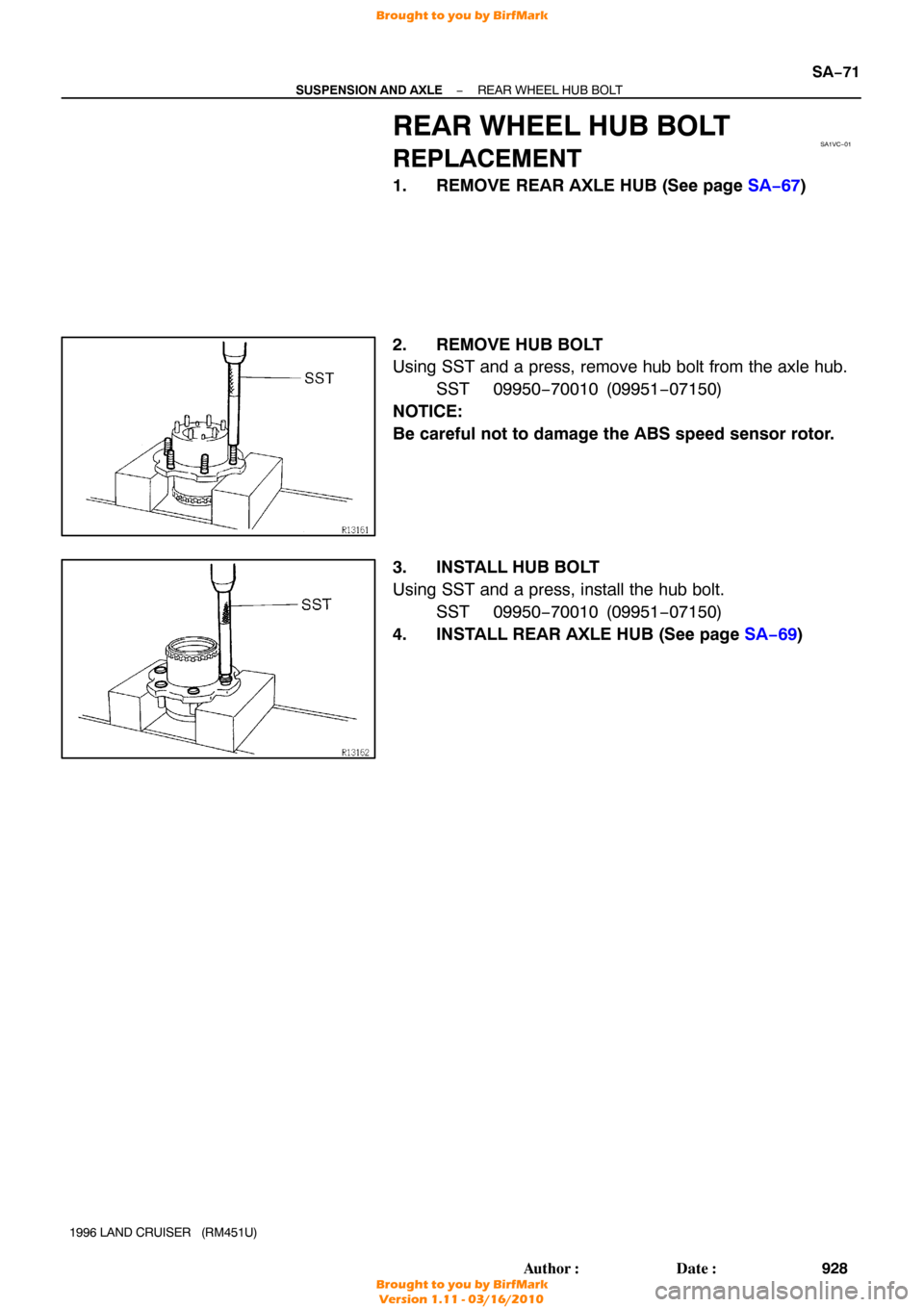
1. REMOVE REAR AXLE HUB (See page SA−67 )
2. REMOVE HUB BOLT
Using SST and a press, remove hub bolt from the axle hub. SST 09950−70010 (09951 −07150)
NOTICE:
Be careful not to damage the ABS speed sensor rotor.
3. INSTALL HUB BOLT
Using SST and a press, install the hub bolt. SST 09950−70010 (09951 −07150)
4. INSTALL REAR AXLE HUB (See page SA−69 )
Brought to you by BirfMark
Brought to you by BirfMark
Version 1.11 - 03/16/2010
Page 1165 of 1399

(6) Check the voltage between the terminals")
Z07254
M3 M4 M1 M2
Z07255
Wire Harness Side
SA−102
−
SUSPENSION AND AXLE DIFFERENTIAL LOCKING SYSTEM
959
Author�: Date�:
1996 LAND CRUISER (RM451U)
(6) Check the voltage between the terminals of the Diff.
lock ECU when switching the Diff. lock control
switch with the speedometer, registering approx. 8
km/h (5 mph) or more.
(7) Check that the indicator lights blink when center Diff. lock release mode is set.
Diff. lock is released for both the front wheels and
rear wheels at this time.
(8) Return the Diff. lock control switch to OFF.
(9) Stop the engine and lower the vehicle.
2. INSPECT DIFF. LOCK SYSTEM CIRCUIT
(a) Inspect the system circuit with connector disconnected. Disconnect the connector from the Diff. lock ECU and in-
spect the connector on the wire harness side, as shown
in the chart.
Trouble Part/
Terminals (Symbols)ConditionSpecified V alue
Rear diff. lock actuator/
1 (M2) − 3 (M1)−Less than 100 Ω
Front diff. lock actuator/
5 (M4) − 7 (M1)−Less than 100 Ω
Body ground/
13 (GND) − Body ground−Continuity
Vehicle speed sensor/
4(SPD) − Body groundVehicle moving slowly1 pulse each 40 cm (15.75 in.)
Brought to you by BirfMark
Brought to you by BirfMark
Version 1.11 - 03/16/2010
Page 1168 of 1399

4. INSPECT DIFF. LOCK CONTROL SWITCH
Inspect the switch conti")
SA1948
21
4
Z07264
Ohmmeter
−
SUSPENSION AND AXLE DIFFERENTIAL LOCKING SYSTEM
SA−105
962
Author�: Date�:
1996 LAND CRUISER (RM451U)
4. INSPECT DIFF. LOCK CONTROL SWITCH
Inspect the switch continuity between terminals, as shown.
Switch PositionTerminalsSpecified Condition
OFF1 − 2No continuity
1 − 4No continuity
RR1 − 2No continuity
1 − 4Continuity
FR RR1 − 2Continuity
1 − 4Continuity
If continuity is not as specified, replace the switch.
5. INSPECT DIFF. LOCK POSITION SWITCH
(a) Front and Rear:
Inspect the diff. lock position switch.
(1) Check that there is continuity between terminalswhen the switch is pushed (differential connected
position).
(2) Check that there is no continuity when the switch is
free (differential disconnected position).
If operation is not as specified, replace the switch.
(b) Inspect the center diff. indicator switch.
6. INSPECT VEHICLE SPEED SENSOR AND INDICATOR
LIGHT
(a) Inspect the vehicle speed sensor (See page BE−34).
(b) Inspect the indicator light.
Brought to you by BirfMark
Brought to you by BirfMark
Version 1.11 - 03/16/2010
Page 1228 of 1399

THROTTLE BODY
ON−VEHICLE INSPECTION
1. INSPECT THROTTLE BODY
(a) Check that the throttle linkage moves smoot")
SF1EU−01
SF−42
−
SFI THROTTLE BODY
670
Author�: Date�:
1996 LAND CRUISER (RM451U)
THROTTLE BODY
ON−VEHICLE INSPECTION
1. INSPECT THROTTLE BODY
(a) Check that the throttle linkage moves smoothly.
(b) Check the vacuum at each port.
�Start the engine.
�Check the vacuum with your finger.
Port nameAt idleAt 3,500 rpm
PNo vacuumVacuum
ENo vacuumVacuum
RNo vacuumVacuum
2. INSPECT THROTTLE POSITION (TP) SENSOR
(a) Disconnect the TP sensor connector.
(b) Apply vacuum to the throttle opener.
(c) Using an ohmmeter, measure the resistance between
each terminal.
Throttle valve
conditionBetween terminalsResistance
Fully closedVTA − E20.2 − 5.7 kΩ
Fully closedIDL − E22.3 kΩ or less
OpenIDL − E2Infinity
Fully openVTA − E22.0 − 10.2 kΩ
−VC − E22.5 − 5.9 kΩ
(d) Reconnect the TP sensor connector.
3. INSPECT AND ADJUST DASHPOT
(a) Allow the engine to warm up to normal operating tempera-
ture.
(b) Check the idle speed.
Idle speed: 650 ± 50 rpm (N position)
(c) Open the throttle valve until the throttle lever separates from the dashpot end.
(d) Release the throttle valve gradually, and check the dash-
pot setting speed when the throttle lever touched the
dashpot end.
Dashpot setting speed: 2,200 ± 300 rpm
Brought to you by BirfMark
Brought to you by BirfMark
Version 1.11 - 03/16/2010
Page 1312 of 1399

SFI
SERVICE DATA
Fuel pressure
regulatorFuel pressure at no vacuum265 − 304 kPa (2.7 − 3.1 kgf/c")
SS1ES−01
−
SERVICE SPECIFICATIONS SFI
SS−11
134
Author�: Date�:
1996 LAND CRUISER (RM451U)
SFI
SERVICE DATA
Fuel pressure
regulatorFuel pressure at no vacuum265 − 304 kPa (2.7 − 3.1 kgf/cm2, 38 − 44 psi)
Fuel pumpResistance at 20°C (68° F)0.2 − 3.0 Ω
InjectorResistance at 20°C (68° F)
Injection volume
Difference between each cylinder
Fuel leakage13.4 − 14.2 Ω
69 − 88 cm3 (4.2 − 5.4 cu in.) per 15 sec.
5 cm3 (0.3 cu in.) or less
1 drop or less per 12 min.
MAF meterResistance (THA − E2) at −20° C (− 4°F)
at 0° C (32° F)
at 20° C (68° F)
at 40° C (104° F)
at 60° C (140° F)
at 80° C (176° F)10 − 20 kΩ
4 − 7 kΩ
2 − 3 kΩ
0.9 − 1.3 kΩ
0.4 − 0.7 kΩ
0.2 − 0.4 kΩ
Throttle bodyThrottle body fully closed angle
Dashpot setting speed
Throttle opener setting speed6°
2,200 ± 300 rpm
700 − 1,000 rpm
Throttle position
sensorClearance between stop screw and lever
0 mm (0 in.) VTA − E2
0.50 mm (0.020 in.) IDL − E2
0.75 mm (0.030 in.) IDL − E2
Throttle valve fully open VTA − E2
− VC − E2
0.2 − 5.7 kΩ
2.3 kΩ or less
Infinity
2.0 − 10.2 kΩ
2.5 − 5.9 kΩ
IAC valveResistance (B1 − S1 and S3, B2 − S2 and S4)
at cold (− 10 − 50 ° C (−50 − 122° F))
at hot (50 − 100°C (122 − 212°F))
15 − 25 Ω
20 − 30 Ω
Fuel pump resistorResistance at 20°C (68° F)0.70 − 0.76 Ω
VSV for fuel pres-
sure controlResistance at 20°C (68° F)37 − 44 Ω
ECT sensorResistance at −20° C (− 4°F)
0 °C (32° F)
20 °C (68° F)
40 °C (104° F)
60 °C (140° F)
80 °C (176° F)10 − 20 kΩ
4 − 7 kΩ
2 − 3 kΩ
0.9 − 1.3 kΩ
0.4 − 0.7 kΩ
0.2 − 0.4 kΩ
EGR gas temp
sensorResistance at 50°C (122° F)
at 100° C (212° F)
150 °C (302° F)64 − 97 kΩ
11 − 16 kΩ
2 − 4 kΩ
Heated oxygen
sensorHeater coil resistance at 20°C (68° F)11 − 16 Ω
Fuel cut rpmFuel return rpm1,200 rpm
Brought to you by BirfMark
Brought to you by BirfMark
Version 1.11 - 03/16/2010
Page 1325 of 1399

TORQUE SPECIFICATION
Part tightenedN·mkgf·cmft·lbf
Valve body x Transmission case101007
Oil staine")
SS1E7−01
SS−24
−
SERVICE SPECIFICATIONS AUTOMATIC TRANSMISSION
1996 LAND CRUISER (RM451U)
TORQUE SPECIFICATION
Part tightenedN·mkgf·cmft·lbf
Valve body x Transmission case101007
Oil stainer x Valve body101007
Oil pan7.47565 in.·lbf
Drain plug x Oil pan2020515
Parking lock pawl bracket x Transmission case7.47565 in.·lbf
Front propeller shaft x Front dif ferential7475054
Front propeller shaft x Transfer7475054
Rear propeller shaft x Transfer8890065
Rear propeller shaft x Rear dif ferential8890065
Drive plate x Crankshaft981,00072
Torque converter clutch x Drive plate5555040
Front exhaust pipe x Exhaust manifold6263046
Front exhaust pipe x TWC3940029
Oil cooler pipe3435025
Transmission x Engine7173053
Exhaust pipe clamp1919514
Park/neutral position switch Nut
Bolt6.9 1370
13061 in.·lbf 9
No. 2 vehicle speed sensor5.45548 in.·lbf
Speedometer driven gear sleeve x Locking plate1616012
Starter mounting bolt3940029
Transfer shift lever1818513
Stabilizer bar bracket mounting bolt1818513
Engine under cover mounting bolt2829021
Exhaust pipe No. 1 support bracket x Torque converter clutch housing2424017
Crossmember x Frame6162045
Engine rear mounting x Crossmember7475054
Transmission shift lever assembly x Body5.45548 in.·lbf
Oil cooler mounting bolt1111 58
Brought to you by BirfMark
Brought to you by BirfMark
Version 1.11 - 03/16/2010

(g) Check the distance between top surface of axle housing
and the lock nut.
Standard distance")