Page 1332 of 1399

Front dif
ferential
(cont’d)
Drive pinion adjusting plate washer thickness1.70 mm (0.0669 in.)")
−
SERVICE SPECIFICATIONS SUSPENSION AND AXLE
SS−31
154
Author�: Date�:
1996 LAND CRUISER (RM451U)
Front dif
ferential
(cont’d)
Drive pinion adjusting plate washer thickness1.70 mm (0.0669 in.)
1.73 mm (0.0681 in.)
1.76 mm (0.0693 in.)
1.79 mm (0.0705 in.)
1.82 mm (0.0717 in.)
1.85 mm (0.0728 in.)
1.88 mm (0.0740 in.)
1.91 mm (0.0752 in.)
1.94 mm (0.0764 in.)
1.97 mm (0.0776 in.)
2.00 mm (0.0787 in.)
2.03 mm (0.0799 in.)
2.06 mm (0.0811 in.)
2.09 mm (0.0823 in.)
2.12 mm (0.0835 in.)
2.15 mm (0.0846 in.)
2.18 mm (0.0858 in.)
2.21 mm (0.0870 in.)
2.24 mm (0.0882 in.)
2.27 mm (0.0894 in.)
2.30 mm (0.0906 in.)
2.33 mm (0.0917 in.)
Rear dif ferentialDrive pinion preload (at starting) New bearing
Reused bearing1.3 − 2.0 N·m (13 − 20 kgf·cm, 11.3 − 17.4 in.·lbf)
0.7 − 1.0 N·m (7 − 10 kgf·cm, 6.1 − 8.7 in.·lbf)
Total preload (at starting)
w/o Differntial lockw/ Differntial lockDrive pinion preload plus
0.4 − 0.6 N·m (4 − 6 kgf·cm, 3.5 − 5.2 in.·lbf)
0.3 − 0.7 N·m (3 − 7 kgf·cm, 2.6 − 6.1 in.·lbf)
Drive pinion to ring gear backlash0.15 − 0.20 mm (0.0059 − 0.0079 in.)
Pinion gear to side gear backlash0.02 − 0.20 mm (0.0008 − 0.0079 in.)
Ring gear runout Max.0.10 mm (0.0039 in.)
Companion flange runoutMax. Radial
Lateral0.10 mm (0.0039 in.)
0.10 mm (0.0039 in.)
Oil seal drive in depth1.0 mm (0.039 in.)
Side gear thrust washer thickness1.60 mm (0.0630 in.)
1.75 mm (0.0689 in.)
1.90 mm (0.0748 in.)
2.05 mm (0.0807 in.)
Drive pinion adjusting plate washer thickness1.05 mm (0.0413 in.)
1.10 mm (0.0433 in.)
1.15 mm (0.0453 in.)
1.20 mm (0.0472 in.)
1.25 mm (0.0492 in.)
1.30 mm (0.0512 in.)
1.35 mm (0.0531 in.)
1.40 mm (0.0551 in.)
1.45 mm (0.0571 in.)
1.50 mm (0.0591 in.)
1.55 mm (0.0610 in.)
Brought to you by BirfMark
Brought to you by BirfMark
Version 1.11 - 03/16/2010
Page 1333 of 1399
SS−32
−
SERVICE SPECIFICATIONS SUSPENSION AND AXLE
155
Author�: Date�:
1996 LAND CRUISER (RM451U)
Rear dif
ferential
(cont’d)
Side bearing adjusting plate thickness
(w/ Differential lock only)2.67 mm (0.1051 in.)
2.70 mm (0.1063 in.)
2.73 mm (0.1075 in.)
2.76 mm (0.1087 in.)
2.79 mm (0.1098 in.)
2.82 mm (0.1110 in.)
2.85 mm (0.1122 in.)
2.88 mm (0.1134 in.)
2.91 mm (0.1146 in.)
2.94 mm (0.1157 in.)
2.97 mm (0.1169 in.)
3.00 mm (0.1181 in.)
3.03 mm (0.1193 in.)
3.06 mm (0.1205 in.)
3.09 mm (0.1217 in.)
3.12 mm (0.1228 in.)
3.15 mm (0.1240 in.)
3.18 mm (0.1252 in.)
3.21 mm (0.1264 in.)
3.24 mm (0.1276 in.)
3.27 mm (0.1287 in.)
3.30 mm (0.1299 in.)
3.33 mm (0.1311 in.)
Rear axleRear axle shaft runout Max.
Distance between top surface of axle housing and lock nut0.8 mm (0.031 in.)
− 0.2 − 0.9 mm (− 0.0079 − 0.0354 in.)
Brought to you by BirfMark
Brought to you by BirfMark
Version 1.11 - 03/16/2010
Page 1334 of 1399

TORQUE SPECIFICATION
Part tightenedN·mkgf·cmft·lbf
FRONT
Axle hub x Disc6465047
Axle hub bearing lock")
SS1ED−02
−
SERVICE SPECIFICATIONS SUSPENSION AND AXLE
SS−33
1996 LAND CRUISER (RM451U)
TORQUE SPECIFICATION
Part tightenedN·mkgf·cmft·lbf
FRONT
Axle hub x Disc6465047
Axle hub bearing lock nut6465047
Flange x Axle hub3536026
Brake caliper x Axle carrier1231,25090
Brake caliper x Flexible hose3031022
Steering knuckle x Knuckle arm9698071
Bearing cap x Steering knuckle9698071
Knuckle arm x Tie rod9192567
Steering knuckle x Knuckle spindle4747534
Oil seal end retainer x Knuckle arm5.45548 in.·lbf
ABS speed sensor set bolt x Steering knuckle1818513
Hub nut Steel wheel
Aluminum wheel147
1031,500
1,050109 76
Drain plug4950036
Filler plug4950036
Propeller shaft x Companion flange8890065
Side bearing cap x Differential carrier7880058
Ring gear x Differential case9798571
Drive pinion x Companion flange196 − 3432,000 − 3,500145 − 253
Differential LH case x RH case4748035
Differential lock shift retainer2424017
Differential lock screw plug2222016
Differential lock indicator switch4041030
Differential lock actuator2627020
Differential carrier x Axle housing2728020
Adjusting nut lock x Bearing cap131309
Follow spring x Frame9.29482 in.·lbf
Stabilizer bar x Axle housing2526019
Shock absorber x Axle housing6970051
Shock absorber x Frame6970051
Stabilizer bar link x Cover1818513
Stabilizer bar link x Link bracket1031,05076
Lateral control rod x Frame1711,750127
Lateral control rod x Axle housing1711,750127
Leading arm x Frame1771,800130
Leading arm x Axle housing1711,750127
REAR
Rear axle shaft x Axle hub3434025
Rear axle bearing lock nut5960043
Rear axle bearing lock nut screw5.45548 in.·lbf
Brke caliper x Axle carrier1031,05076
ABS speed sensor set bolt1818513
Brought to you by BirfMark
Brought to you by BirfMark
Version 1.11 - 03/16/2010
Page 1335 of 1399

Hub nut
Steel wheel
Aluminum wheel
147
1031,500
1,050109 76
Drain plug4950036
Filler plug4950036
Pinion shaft pin w/")
SS−34
−
SERVICE SPECIFICATIONS SUSPENSION AND AXLE
1996 LAND CRUISER (RM451U)
Hub nut
Steel wheel
Aluminum wheel
147
1031,500
1,050109 76
Drain plug4950036
Filler plug4950036
Pinion shaft pin w/o Differential lock
w/ Differential lock27
58275
59020
43
Propeller shaft x Companion flange7475054
Side bearing cap x Differential carrier w/o Differential lock
w/ Differential lock78
11 3800
1,15058
83
Ring gear x Differential case11 01,12581
Companion flange x Drive pinion (Maximum torque)4414,500325
Differential carrier x Axle housing7374054
Adjusting nut lock x Bearing cap131309
Differential case x Differential cover5859043
Differential lock shift fork set bolt2020014
Differential lock actuator2424017
Differential lock cover1818513
Differential lock indicator switch4041030
Actuator protector Nut
Bolt35
20360
20026
14
Follow spring x Frame2829021
Shock absorber x Bracket6970051
Shock absorber bracket x Frame5051037
Shock absorber x Axle housing6465047
Lateral control rod x Frame1771,800130
Lateral control rod x Axle housing2452,500181
Upper control rod x Frame1771,800130
Upper control rod x Axle housing1771,800130
Lower control arm x Frame1771,800130
Lower control arm x Axle housing1771,800130
Stabilizer bar x Link2526019
Stabilizer bar link x Link bracket1031,05076
Cover x Axle housing1818513
Brought to you by BirfMark
Brought to you by BirfMark
Version 1.11 - 03/16/2010
Page 1364 of 1399
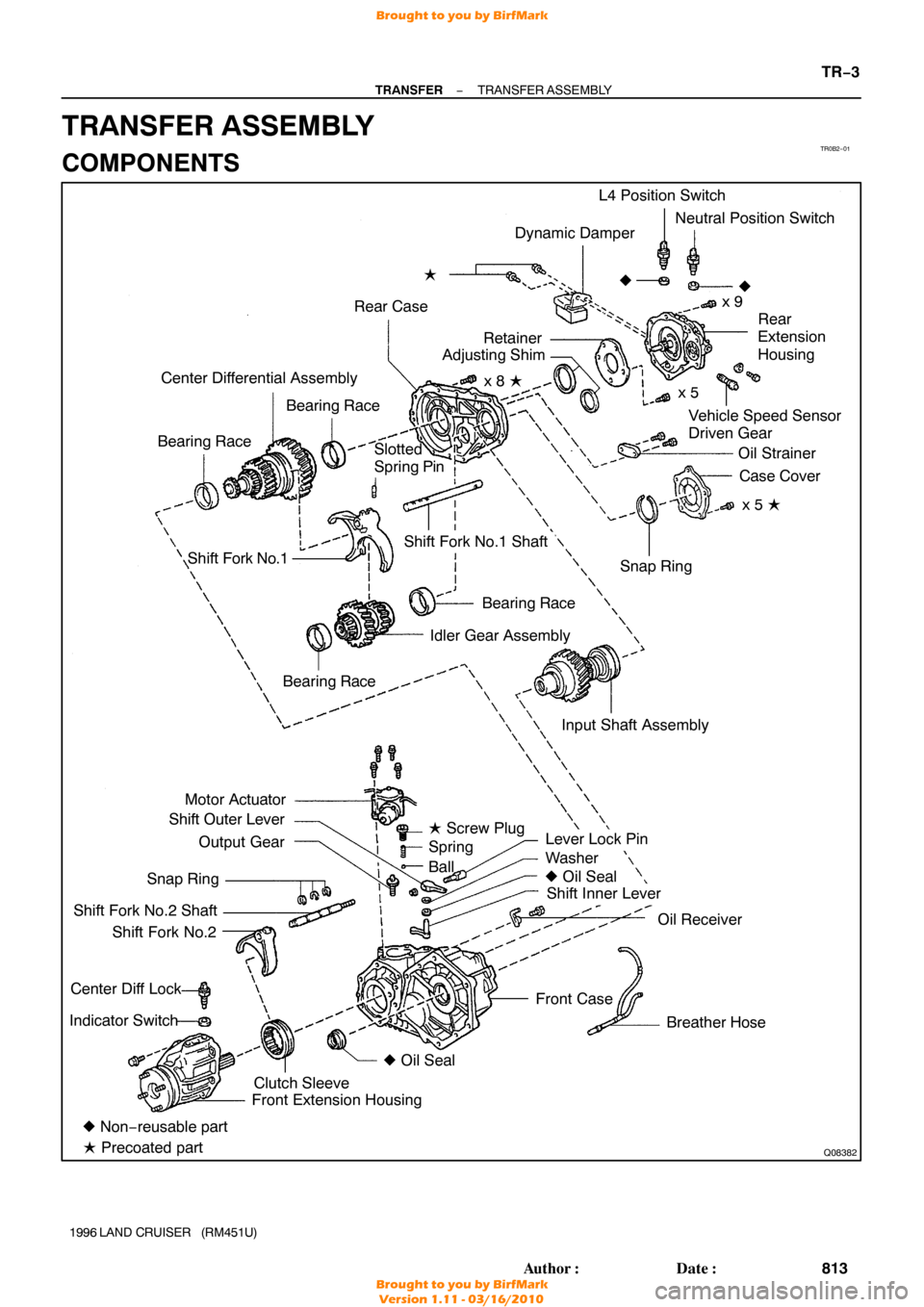
TR0B2−01
Q08382
Dynamic Damper
Rear Case �
Vehicle Speed Sensor
Driven Gear
Center Differential Assembly
Bearing Race
Bearing Race L4 Position Switch
Neutral Position Switch
x 9
�
Rear
Extension
Housing
Oil Strainer Case Cover
x 5 �
Shift Fork No.1
Bearing Race
Idler Gear Assembly
Motor Actuator
Shift Outer Lever
Output Gear
Snap Ring
Shift Fork No.2 Shaft Shift Fork No.2
Center Diff Lock
Indicator Switch
Lever Lock Pin
Washer
� Oil Seal
Shift Inner Lever
Oil Receiver
Breather Hose
Front Case Snap Ring
Shift Fork No.1 Shaft
� Non− reusable part
� Precoated part Front Extension Housing
Clutch Sleeve �
Oil Seal
Bearing Race
�
Slotted
Spring Pin
Input Shaft Assemblyx 5
x 8 �
Retainer
Adjusting Shim
� Screw Plug
Spring
Ball
−
TRANSFER TRANSFER ASSEMBLY
TR−3
813
Author�: Date�:
1996 LAND CRUISER (RM451U)
TRANSFER ASSEMBLY
COMPONENTS
Brought to you by BirfMark
Brought to you by BirfMark
Version 1.11 - 03/16/2010
Page 1365 of 1399

DISASSEMBLY
1. REMOVE BREATHER HOSE
2. REMOVE DYNAMIC DAMPER
Remove the 2 bolts and dynamic damper.
HIN")
TR0CM−01
Q07105
Q07124
FIPG
TR−4
−
TRANSFER TRANSFER ASSEMBLY
1996 LAND CRUISER (RM451U)
DISASSEMBLY
1. REMOVE BREATHER HOSE
2. REMOVE DYNAMIC DAMPER
Remove the 2 bolts and dynamic damper.
HINT:
At the time of reassembly, apply adhesive to the bolt threads. Adhesive: Part No.08833 −00070, THREE BOND 1324
or equivalent
Torque: 37 N·m (380 kgf·cm, 27 ft·lbf)
3. REMOVE MOTOR ACTUATOR
Remove the 4 bolts and motor actuator.
HINT:
At the time of reassembly, please refer to the following items.
�Set the motor actuator in differential lock condition.
�Apply FIPG to the front case.
FIPG: Part No. 08826−00090, THREE BOND 1281 or
equivalent
Torque: 18 N·m (185 kgf·cm, 13 ft·lbf)
4. REMOVE OUTPUT GEAR FROM FRONT CASE
HINT:
At the timie of reassembly apply gear oil to the output gear.
NOTICE:
At the time of reassembly, do not turn the output gear.
5. REMOVE SCREW PLUG, SPRING AND BALL
(a) Using a torx socket wrench (T40), remove the screw plug.
HINT:
At the time of reassembly, apply liquid sealer to the screw plug. Sealant: Part No.08833−00080, THREE BOND 1344,
LOCTITE 242 or equivalent
Torque:19 N·m (190 kgf·cm, 14 ft·lbf)
(b) Using a magnetic finger, remove the spring and ball.
Brought to you by BirfMark
Brought to you by BirfMark
Version 1.11 - 03/16/2010
Page 1366 of 1399

6. REMOVE TRANSFER INDICATOR SWITCH
Remove the Center Diff Lock indicator switch, L4 position")
Q04610
Q00541
Front
Q02950
Q07125
FIPG
−
TRANSFER TRANSFER ASSEMBLY
TR−5
1996 LAND CRUISER (RM451U)
6. REMOVE TRANSFER INDICATOR SWITCH
Remove the Center Diff Lock indicator switch, L4 position
switch, Neutral position switch and 3 gaskets.
Torque: 37 N·m (380 kgf·cm, 27 ft·lbf)
7. REMOVE FRONT EXTENSION HOUSING
Remove the 6 bolts and front extension housing.
HINT:
If necessary, tap the front extension housing with a plastic ham-
mer.
HINT:
At the time of reassembly, please refer to the following items.
�Set the clutch sleeve in differential lock condition.
�Apply FIPG to the front case.
FIPG: Part No. 08826−00090, THREE BOND 1281 or
equivalent
Torque: 37 N·m (380 kgf·cm, 27 ft·lbf)
8. REMOVE CLUTCH SLEEVE, SHIFT FORK NO.2 SHAFT AND SHIFT FORK NO.2
HINT:
At the time of reassebly, make sure to install the clutch sleeve
in the correct direction.
9. SEPARATE SHIFT FORK NO.2 SHAFT AND SHIFT FORK NO.2
(a) Using 2 screwdrivers and a hammer, tap out the 3 snap rings from the shift fork No.2 shaft.
(b) Separate the shift fork No.2 shaft and shift fork No.2.
10. REMOVE REAR EXTENSION HOUSING
Remove the 9 bolts and rear extension housing.
HINT:
If necessary, tap the rear extension housing with a plastic ham-
mer.
HINT:
At the time of reassembly, apply FIPG to the rear case. FIPG: Part No. 08826−00090, THREE BOND 1281 or
equivalent
Torque: 37 N·m (380 kgf·cm, 27 ft·lbf)
Brought to you by BirfMark
Brought to you by BirfMark
Version 1.11 - 03/16/2010
Page 1369 of 1399

FIPG: Part No. 08826−00090, THREE BOND 1281 or
equival")
TF0854
TF0986
TF0857
Q07130
RemovalInstallation
Socket Wrench Socket Wrench
TR−8
−
TRANSFER TRANSFER ASSEMBLY
1996 LAND CRUISER (RM451U)
FIPG: Part No. 08826−00090, THREE BOND 1281 or
equivalent
16. REMOVE 2 BEARING RACES FROM REAR CASE
17. REMOVE INPUT SHAFT ASSEMBLY
Using a plastic hammer, remove the input shaft assembly.
18. REMOVE IDLER GEAR ASSEMBLY, CENTER DIFFER-
ENTIAL ASSEMBLY, SHIFT FORK NO.1 AND SHIFT
FORK NO.1 SHAFT FROM FRONT CASE
19. SEPARATE SHIFT FORK NO.1 AND SHIFT FORK NO.1 SHAFT
(a) Using a pin punch and hammer, drive out the slotted spring pin.
(b) Separate the shift fork No.1 and shift fork No.1 shaft.
20. REMOVE SHIFT OUTER LEVER AND INNER LEVER
(a) Remove the nut and washer from the shift outer lever. Torque: 12 N·m (120 kgf·cm, 9 ft·lbf)
(b) Using a brass bar, hammer and socket wrench, tap out the lever lock pin.
(c) Remove the shift outer lever, washer and inner lever from
the front case.
21. REMOVE OIL RECEIVER FROM FRONT CASE
Remove the bolt and oil receiver. Torque: 12 N·m (120 kgf·cm, 9 ft·lbf)
Brought to you by BirfMark
Brought to you by BirfMark
Version 1.11 - 03/16/2010