Page 801 of 1399
EM−16
−
ENGINE MECHANICAL TIMING CHAIN
1996 LAND CRUISER (RM451U)
19. REMOVE CRANKSHAFT TIMING GEAR
HINT:
If necessary, remove the gear with SST.
SST 09950−40010 (09951 −04010, 09952−04010,
09953 −04020, 09954 −04010, 09955 −04060),
09950 −60010 (09951 −00350)
20. REMOVE CHAIN TENSIONER SLIPPER AND VIBRA- TION DAMPER
(a) Using a 10 mm hexagon wrench, remove the bolt and slip-
per.
(b) Remove the 2 bolts and damper.
21. REMOVE OIL JET
Remove the bolt and oil jet.
22. REMOVE CRANKSHAFT ROTOR
23. REMOVE OIL PUMP DRIVE SHAFT GEAR
24. REMOVE PUMP DRIVE SHAFT GEAR
If the pump drive shaft gear cannot be removed by hand, use
2 screwdrivers.
NOTICE:
Position shop rags as shown to prevent damage.
Brought to you by BirfMark
Brought to you by BirfMark
Version 1.11 - 03/16/2010
Page 804 of 1399
EM1EB−01
−
ENGINE MECHANICAL TIMING CHAIN
EM−19
1996 LAND CRUISER (RM451U)
INSTALLATION
1. SET CRANKSHAFT
Turn the crankshaft until the set key on crankshaft facing down-
ward.
2. INSTALL PUMP DRIVE SHAFT GEAR
3. INSTALL OIL PUMP DRIVE SHAFT GEAR
(a) Apply a light coat of engine oil on the shaft portion of the
gear.
(b) Install the gear.
4. INSTALL CRANKSHAFT ROTOR
5. INSTALL OIL JET
Install the oil jet with the bolt. Torque: 20 N·m (200 kgf·cm, 14 ft·lbf)
6. INSTALL CHAIN TENSIONER SLIPPER AND VIBRA- TION DAMPER
(a) Install the damper with the 2 bolts.
Torque: 20 N·m (200 kgf·cm, 14 ft·lbf)
(b) Using a 10 mm hexagon wrench, install the slipper with the bolt.
Torque: 69 N·m (700 kgf·cm, 51 ft·lbf)
Brought to you by BirfMark
Brought to you by BirfMark
Version 1.11 - 03/16/2010
Page 807 of 1399

EM−22
−
ENGINE MECHANICAL TIMING CHAIN
1996 LAND CRUISER (RM451U)
(d) Engage the gear of the oil pump drive rotor with the gear
of the oil pump drive gear, and install the oil pump.
(e) Install the oil pump and drive belt adjusting bar with the 9 bolts and 2 nuts.
Torque: 21 N·m (210 kgf·cm, 15 ft·lbf)
HINT:
Each bolt length is indicated in the illustration.
Bolt A: 30 mm (1.18 in.)
Bolt B: 50 mm (1.97 in.)
Bolt C: 60 mm (2.38 in.)
(f) Remove the cord from the chain.
10. INSTALL DRIVE BELT IDLER PULLEY
Install the pulley with the bolt. Torque: 43 N·m (440 kgf·cm, 32 ft·lbf)
11. INSTALL CRANKSHAFT PULLEY
(a) Align the pulley set key with the key groove of the pulley, and slide on the pulley.
(b) Using SST, install and torque the pulley bolt.
SST 09213−58012, 09330 −00021
Torque: 412 N·m (4,200 kgf·cm, 304 ft·lbf)
12. INSTALL NO. 1 OIL PAN (See page LU−12)
13. INSTALL NO. 2 OIL PAN (See page LU−12)
14. INSTALL BOLTS HOLDING NO. 1 OIL PAN TO TRANS-
MISSION HOUSING
Install the 6 bolts. Torque: 72 N·m (730 kgf·cm, 53 ft·lbf)
Brought to you by BirfMark
Brought to you by BirfMark
Version 1.11 - 03/16/2010
Page 808 of 1399

−
ENGINE MECHANICAL TIMING CHAIN
EM−23
1996 LAND CRUISER (RM451U)
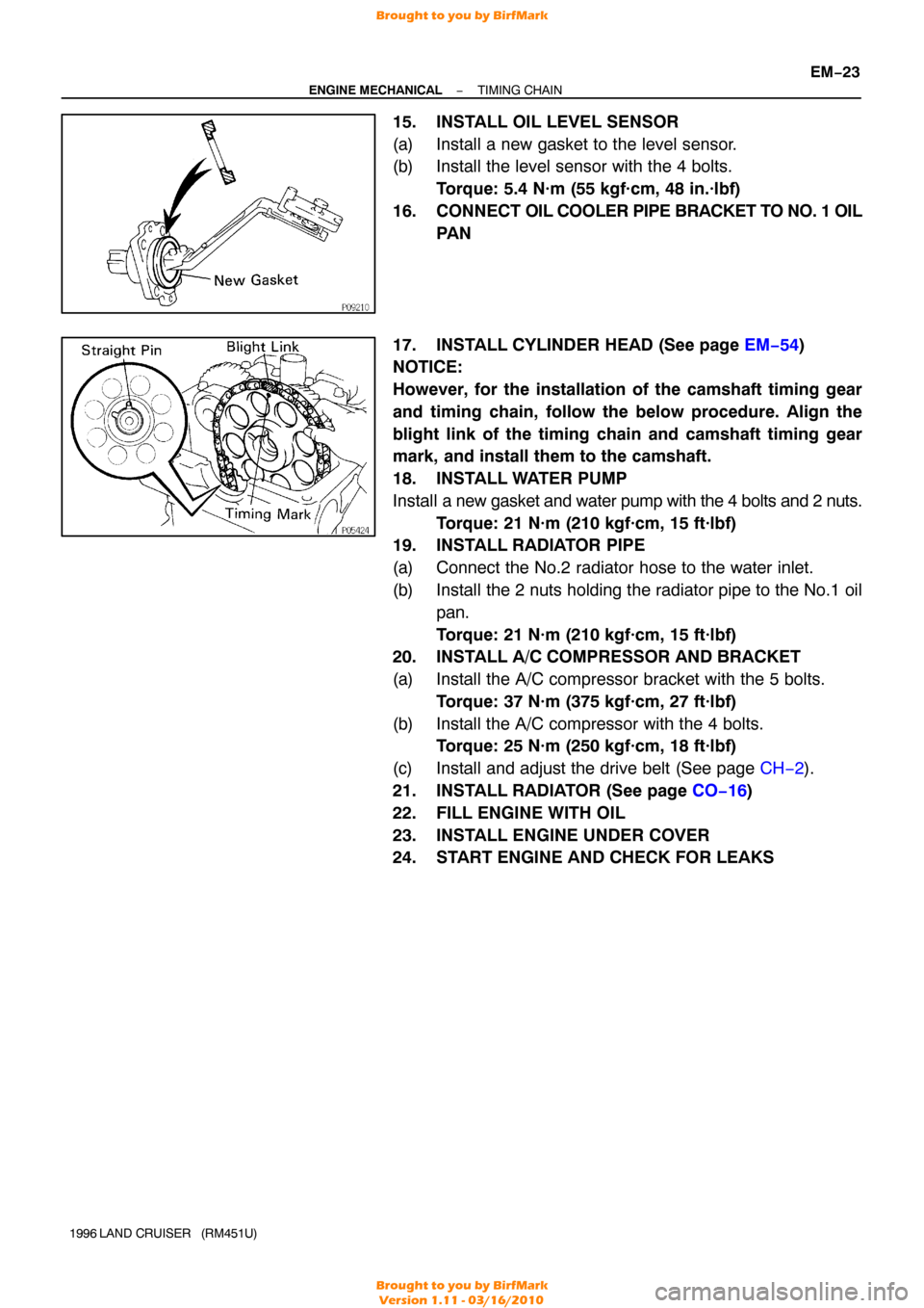
15. INSTALL OIL LEVEL SENSOR
(a) Install a new gasket to the level sensor.
(b) Install the level sensor with the 4 bolts.
Torque: 5.4 N·m (55 kgf·cm, 48 in.·lbf)
16. CONNECT OIL COOLER PIPE BRACKET TO NO. 1 OIL
PA N
17. INSTALL CYLINDER HEAD (See page EM−54 )
NOTICE:
However, for the installation of the camshaft timing gear
and timing chain, follow the below procedure. Align the
blight link of the timing chain and camshaft timing gear
mark, and install them to the camshaft.
18. INSTALL WATER PUMP
Install a new gasket and water pump with the 4 bolts and 2 nuts.
Torque: 21 N·m (210 kgf·cm, 15 ft·lbf)
19. INSTALL RADIATOR PIPE
(a) Connect the No.2 radiator hose to the water inlet.
(b) Install the 2 nuts holding the radiator pipe to the No.1 oil
pan.
Torque: 21 N·m (210 kgf·cm, 15 ft·lbf)
20. INSTALL A/C COMPRESSOR AND BRACKET
(a) Install the A/C compressor bracket with the 5 bolts.
Torque: 37 N·m (375 kgf·cm, 27 ft·lbf)
(b) Install the A/C compressor with the 4 bolts. Torque: 25 N·m (250 kgf·cm, 18 ft·lbf)
(c) Install and adjust the drive belt (See page CH−2).
21. INSTALL RADIATOR (See page CO−16 )
22. FILL ENGINE WITH OIL
23. INSTALL ENGINE UNDER COVER
24. START ENGINE AND CHECK FOR LEAKS
Brought to you by BirfMark
Brought to you by BirfMark
Version 1.11 - 03/16/2010
Page 813 of 1399

EM1E3−01
EM−28
−
ENGINE MECHANICAL CYLINDER HEAD
1996 LAND CRUISER (RM451U)
REMOVAL
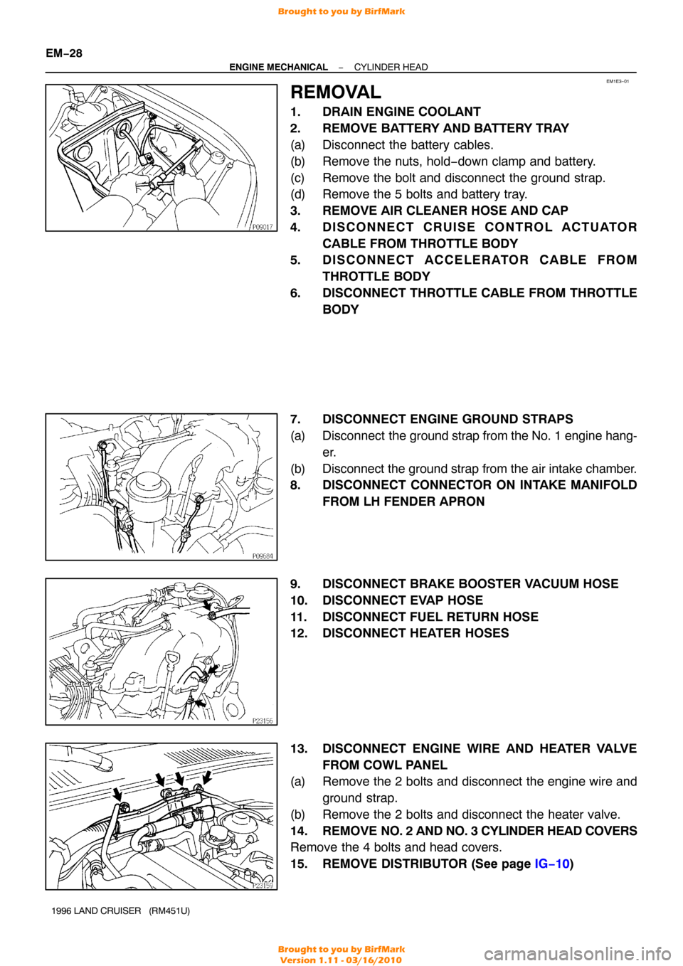
1. DRAIN ENGINE COOLANT
2. REMOVE BATTERY AND BATTERY TRAY
(a) Disconnect the battery cables.
(b) Remove the nuts, hold −down clamp and battery.
(c) Remove the bolt and disconnect the ground strap.
(d) Remove the 5 bolts and battery tray.
3. REMOVE AIR CLEANER HOSE AND CAP
4. DISCONNECT CRUISE CONTROL ACTUATOR CABLE FROM THROTTLE BODY
5. DISCONNECT ACCELERATOR CABLE FROM
THROTTLE BODY
6. DISCONNECT THROTTLE CABLE FROM THROTTLE BODY
7. DISCONNECT ENGINE GROUND STRAPS
(a) Disconnect the ground strap from the No. 1 engine hang-
er.
(b) Disconnect the ground strap from the air intake chamber.
8. DISCONNECT CONNECTOR ON INTAKE MANIFOLD FROM LH FENDER APRON
9. DISCONNECT BRAKE BOOSTER VACUUM HOSE
10. DISCONNECT EVAP HOSE
11. DISCONNECT FUEL RETURN HOSE
12. DISCONNECT HEATER HOSES
13. DISCONNECT ENGINE WIRE AND HEATER VALVE FROM COWL PANEL
(a) Remove the 2 bolts and disconnect the engine wire and
ground strap.
(b) Remove the 2 bolts and disconnect the heater valve.
14. REMOVE NO. 2 AND NO. 3 CYLINDER HEAD COVERS
Remove the 4 bolts and head covers.
15. REMOVE DISTRIBUTOR (See page IG−10 )
Brought to you by BirfMark
Brought to you by BirfMark
Version 1.11 - 03/16/2010
Page 814 of 1399

−
ENGINE MECHANICAL CYLINDER HEAD
EM−29
1996 LAND CRUISER (RM451U)
16. DISCONNECT PS RESERVOIR TANK
Remove the 3 bolts and disconnect the reservoir tank.
17. DISCONNECT RADIATOR INLET HOSE
18. DISCONNECT NO. 3 WATER BYPASS HOSE
19. REMOVE GENERATOR (See page CH−8 )
20. REMOVE THROTTLE BODY (See page SF−45)
21. REMOVE OIL DIPSTICKS AND GUIDES FOR ENGINE AND TRANSMISSION
(a) Remove the 2 mounting bolts.
(b) Pull out the dipstick together with dipstick guide.
(c) Remove the O−ring from the dipstick guide.
22. REMOVE INTAKE MANIFOLD STAY
Remove the 2 bolts and intake manifold stay.
23. DISCONNECT FUEL INLET HOSE
Remove the union bolt and 2 gaskets, and disconnect the fuel
inlet hose from the fuel filter.
24. DISCONNECT ENGINE WIRE
(a) Disconnect the connectors. (1) Disconnect the ECT sender gauge connector.
(2) Disconnect the ECT cut switch connector.
(3) Disconnect the ECT sensor connector.
(4) Disconnect the knock sensor connector.
(5) Disconnect the crankshaft position sensor connec-tor.
(6) Remove the bolt and disconnect the engine wire from the cylinder block.
Brought to you by BirfMark
Brought to you by BirfMark
Version 1.11 - 03/16/2010
Page 815 of 1399

EM−30
−
ENGINE MECHANICAL CYLINDER HEAD
1996 LAND CRUISER (RM451U)
(b) Disconnect the connectors.
(1) Disconnect the knock sensor connector.
(2) Disconnect the oil level sensor connector.
(3) Disconnect the 2 connectors from the transmission.
(4) Disconnect the starter connector.
(c) Disconnect the 2 heated oxygen sensor connectors.
(d) Disconnect the PNP switch connector.
(e) Remove the 2 bolts and disconnect the engine wire from the intake manifold and cylinder block.
(f) Disconnect the PCV hose from the PCV valve.
(g) Remove the bolt holding the engine wire to the intake manifold.
(h) Disconnect the connectors. (1) Disconnect the connector for the emission controlvalve set assembly.
(2) Disconnect the 3 injector connectors.
(i) Disconnect the engine wire clamp.
(j) Disconnect the engine wire clamp.
(k) Disconnect the connectors.
(1) Disconnect the 3 injector connectors.
(2) Disconnect the EGR gas temp. sensor connector.
(l) Disconnect the clamp of the No. 6 injector wire from the bracket.
(m) Disconnect the engine wire from the cylinder head and in-
take manifold.
25. DISCONNECT NO. 2 WATER BYPASS PIPE
Remove the 3 bolts, and disconnect the bypass pipe from the
cylinder head.
Brought to you by BirfMark
Brought to you by BirfMark
Version 1.11 - 03/16/2010
Page 816 of 1399

−
ENGINE MECHANICAL CYLINDER HEAD
EM−31
1996 LAND CRUISER (RM451U)
26. REMOVE FRONT EXHAUST PIPE
(a) Disconnect the heated oxygen sensor connector.
(b) Remove the 2 nuts and 2 bolts holding the front exhaust
pipe to the rear TWC.
(c) Disconnect the front exhaust pipe, and remove the gas- ket.
(d) Loosen the clamp bolt and disconnect the clamp from the
No. 1 support bracket.
(e) Remove the 2 bolts and No. 1 support bracket.
(f) Remove the 4 nuts, front exhaust pipe and 2 gaskets.
27. REMOVE NO. 1 AND NO. 2 EXHAUST MANIFOLDS
(a) Remove the 6 bolts, No. 1 heat insulator and No. 2 heat insulator.
(b) Remove the 13 nuts, No. 1 exhaust manifold, No. 2 ex- haust manifold and 2 gaskets.
28. REMOVE HEATER PIPE
Remove the 2 bolts, 2 nuts, ground cable, heater pipe and gas-
ket.
29. REMOVE WATER BYPASS OUTLET AND PIPE
(a) Remove the 2 bolts and water bypass outlet and pipe.
(b) Remove the 3 O−rings from the water bypass outlet and pipe.
Brought to you by BirfMark
Brought to you by BirfMark
Version 1.11 - 03/16/2010