Page 1531 of 2890
B5M0084A
4. KEY CYLINDER
1) Remove trim panel.
2) Disengage rod from holder�
1.
3) Remove nut from key cylinder, and detach key cylinder.
4) Installation is in the reverse order of removal.
B5M0085
5. STRIKER
Remove two bolts from striker and detach striker.
G5M0492
6. WEATHERSTRIP
1) Place weatherstrip so that its joints meet at lower cen-
ter of vehicle body, and install by inserting flanged portion
from below, as shown in section A—A in figure.
2) Tap along entire length with a rubber hammer to firmly
insert body flange into weatherstrip.
CAUTION:
�Be careful not to install in wrong direction.
�Install weatherstrip carefully and firmly.
G5M0552
B5M0086
B: ADJUSTMENT
1) Loosen striker screw.
2) For lateral adjustment, align striker and latch at their
centers.
29
5-2SERVICE PROCEDURE
3. Rear Gate
Page 1626 of 2890
B6M0436
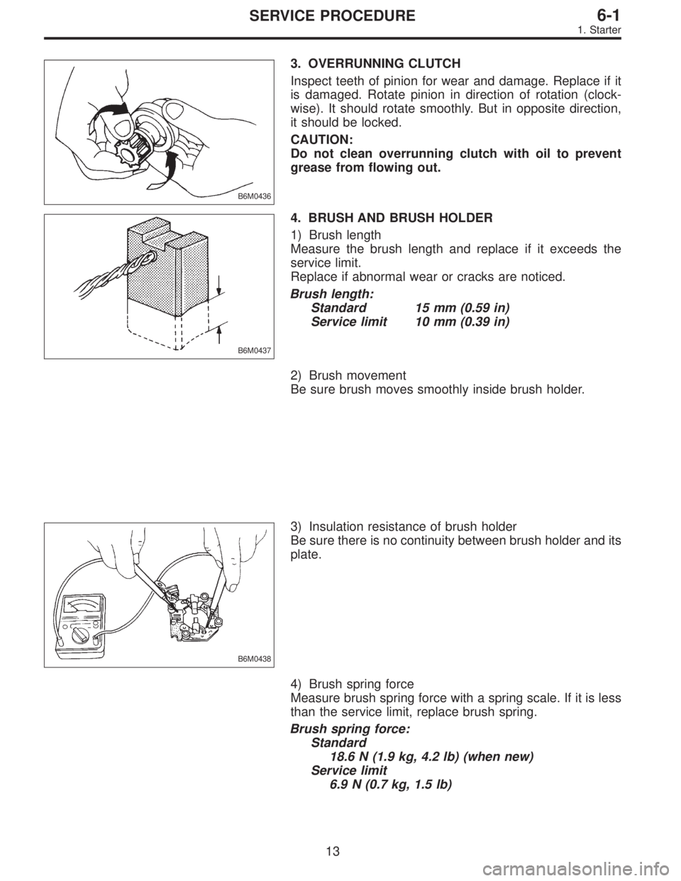
3. OVERRUNNING CLUTCH
Inspect teeth of pinion for wear and damage. Replace if it
is damaged. Rotate pinion in direction of rotation (clock-
wise). It should rotate smoothly. But in opposite direction,
it should be locked.
CAUTION:
Do not clean overrunning clutch with oil to prevent
grease from flowing out.
B6M0437
4. BRUSH AND BRUSH HOLDER
1) Brush length
Measure the brush length and replace if it exceeds the
service limit.
Replace if abnormal wear or cracks are noticed.
Brush length:
Standard 15 mm (0.59 in)
Service limit 10 mm (0.39 in)
2) Brush movement
Be sure brush moves smoothly inside brush holder.
B6M0438
3) Insulation resistance of brush holder
Be sure there is no continuity between brush holder and its
plate.
4) Brush spring force
Measure brush spring force with a spring scale. If it is less
than the service limit, replace brush spring.
Brush spring force:
Standard
18.6 N (1.9 kg, 4.2 lb) (when new)
Service limit
6.9 N (0.7 kg, 1.5 lb)
13
6-1SERVICE PROCEDURE
1. Starter
Page 1633 of 2890
B6M0486
5) Ball bearing
Check rear ball bearing. Replace it if it is noisy or if rotor
does not turn smoothly.
G6M0078
2. STATOR
1) Continuity test
Inspect stator coil for continuity between its terminals.
When there is no continuity between individual terminals,
cable is broken.
Replace stator coil.
G6M0079
2) Insulation test
Inspect stator coil for continuity between stator core and
each terminal. If there is continuity, replace stator coil.
B6M0487A
3. BRUSH
Measure brush length. If brush is worn, replace brush
holder assembly.
Brush length (�):
Standard
20.5 mm (0.807 in)
Limit
1.5 mm (0.059 in)
B6M0488A
4. DIODE ASSEMBLY
The diode consists of eight diodes, four each being located
on the positive and negative sides. The diode is necessary
to restrict current flow to one direction.
Check all diodes, for continuity. If any diode is faulty,
replace diode assembly.
19
6-1SERVICE PROCEDURE
2. Generator
Page 1644 of 2890
B6M0568A
NOTE:
�Length L1 is important in making for easy removal.
�It may be necessary to wrap points A and B with vinyl
tape to prevent them separating while working.
If they do separate, spark plug socket is left on the spark
plug and it is very difficult to remove.
�An approximately 250 mm (9.84 in) long extension is
recommended to be connected to ratchet.
�For spark plug socket, extension and Universal Joint, it
is recommended to use the following tools.
Spark plug socket : PROTO 5020-50
Extension : SNAP-ON FX1
Universal Joint : SNAP-ON FU80B
B6M0569A
9) Set�4extension and�5ratchet in turn onto the con-
nected tools in plug hole, and remove spark plug using
them.
G6M0095
2. #2 SPARK PLUG
1) Disconnect battery ground cable.
B6M0554
2) Remove battery.
30
6-1SERVICE PROCEDURE
3. Spark Plug
Page 1653 of 2890
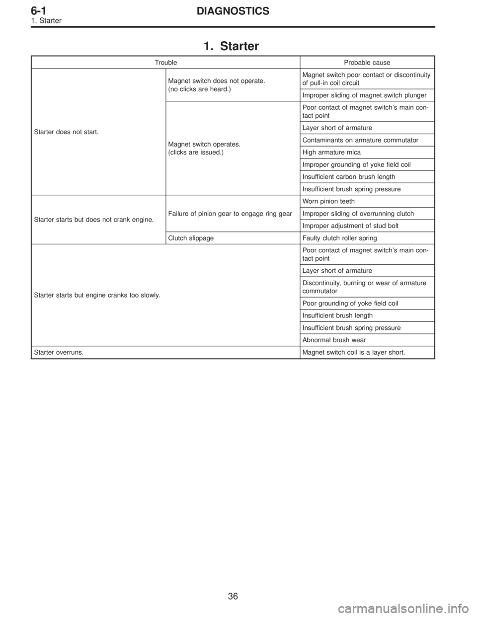
1. Starter
Trouble Probable cause
Starter does not start.Magnet switch does not operate.
(no clicks are heard.)Magnet switch poor contact or discontinuity
of pull-in coil circuit
Improper sliding of magnet switch plunger
Magnet switch operates.
(clicks are issued.)Poor contact of magnet switch’s main con-
tact point
Layer short of armature
Contaminants on armature commutator
High armature mica
Improper grounding of yoke field coil
Insufficient carbon brush length
Insufficient brush spring pressure
Starter starts but does not crank engine.Failure of pinion gear to engage ring gearWorn pinion teeth
Improper sliding of overrunning clutch
Improper adjustment of stud bolt
Clutch slippage Faulty clutch roller spring
Starter starts but engine cranks too slowly.Poor contact of magnet switch’s main con-
tact point
Layer short of armature
Discontinuity, burning or wear of armature
commutator
Poor grounding of yoke field coil
Insufficient brush length
Insufficient brush spring pressure
Abnormal brush wear
Starter overruns.Magnet switch coil is a layer short.
36
6-1DIAGNOSTICS
1. Starter
Page 1693 of 2890
G6M0137
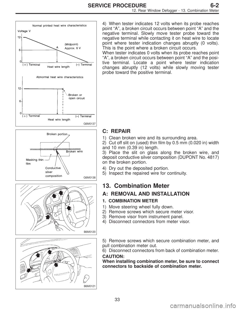
4) When tester indicates 12 volts when its probe reaches
point“A”, a broken circuit occurs between point“A”and the
negative terminal. Slowly move tester probe toward the
negative terminal while contacting it on heat wire to locate
point where tester indication changes abruptly (0 volts).
This is the point where a broken circuit occurs.
When tester indicates 0 volts when its probe reaches point
“A”, a broken circuit occurs between point“A”and the posi-
tive terminal. Locate a point where tester indication
changes abruptly (12 volts) while slowly moving tester
probe toward the positive terminal.
G6M0138
C: REPAIR
1) Clean broken wire and its surrounding area.
2) Cut off slit on (used) thin film by 0.5 mm (0.020 in) width
and 10 mm (0.39 in) length.
3) Place the slit on glass along the broken wire, and
deposit conductive silver composition (DUPONT No. 4817)
on the broken portion.
4) Dry out the deposited portion.
5) Inspect the repaired wire for continuity.
B6M0120
13. Combination Meter
A: REMOVAL AND INSTALLATION
1. COMBINATION METER
1) Move steering wheel fully down.
2) Remove screws which secure meter visor.
3) Remove visor from instrument panel.
4) Disconnect connectors from meter visor.
B6M0121
5) Remove screws which secure combination meter, and
pull combination meter out.
6) Disconnect connectors from back of combination meter.
CAUTION:
When installing combination meter, be sure to connect
connectors to backside of combination meter.
33
6-2SERVICE PROCEDURE
12. Rear Window Defogger - 13. Combination Meter
Page 1694 of 2890
G6M0137
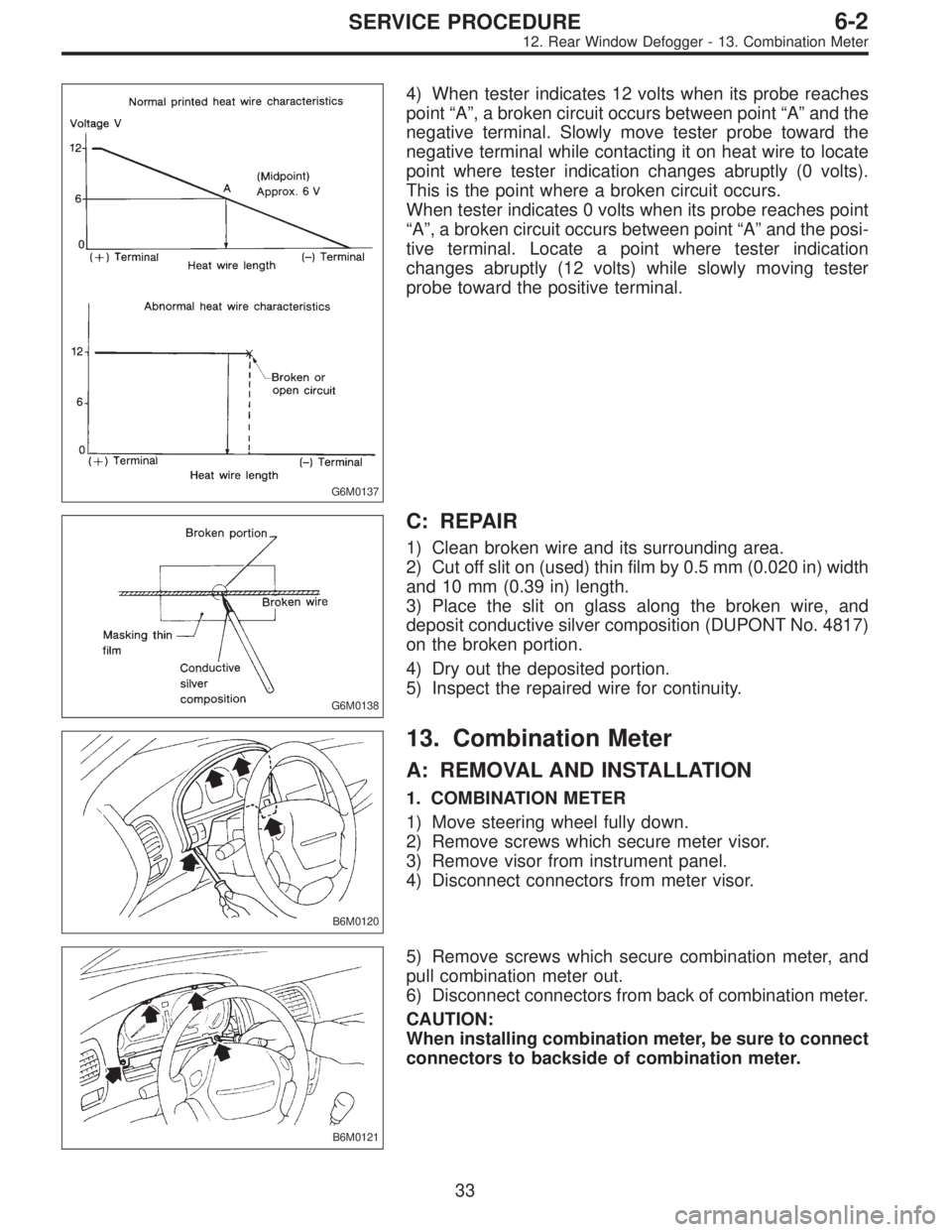
4) When tester indicates 12 volts when its probe reaches
point“A”, a broken circuit occurs between point“A”and the
negative terminal. Slowly move tester probe toward the
negative terminal while contacting it on heat wire to locate
point where tester indication changes abruptly (0 volts).
This is the point where a broken circuit occurs.
When tester indicates 0 volts when its probe reaches point
“A”, a broken circuit occurs between point“A”and the posi-
tive terminal. Locate a point where tester indication
changes abruptly (12 volts) while slowly moving tester
probe toward the positive terminal.
G6M0138
C: REPAIR
1) Clean broken wire and its surrounding area.
2) Cut off slit on (used) thin film by 0.5 mm (0.020 in) width
and 10 mm (0.39 in) length.
3) Place the slit on glass along the broken wire, and
deposit conductive silver composition (DUPONT No. 4817)
on the broken portion.
4) Dry out the deposited portion.
5) Inspect the repaired wire for continuity.
B6M0120
13. Combination Meter
A: REMOVAL AND INSTALLATION
1. COMBINATION METER
1) Move steering wheel fully down.
2) Remove screws which secure meter visor.
3) Remove visor from instrument panel.
4) Disconnect connectors from meter visor.
B6M0121
5) Remove screws which secure combination meter, and
pull combination meter out.
6) Disconnect connectors from back of combination meter.
CAUTION:
When installing combination meter, be sure to connect
connectors to backside of combination meter.
33
6-2SERVICE PROCEDURE
12. Rear Window Defogger - 13. Combination Meter
Page 2154 of 2890
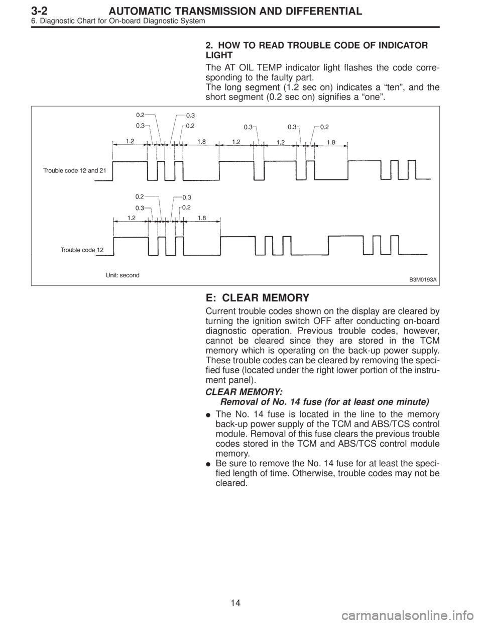
2. HOW TO READ TROUBLE CODE OF INDICATOR
LIGHT
The AT OIL TEMP indicator light flashes the code corre-
sponding to the faulty part.
The long segment (1.2 sec on) indicates a“ten”, and the
short segment (0.2 sec on) signifies a“one”.
B3M0193A
E: CLEAR MEMORY
Current trouble codes shown on the display are cleared by
turning the ignition switch OFF after conducting on-board
diagnostic operation. Previous trouble codes, however,
cannot be cleared since they are stored in the TCM
memory which is operating on the back-up power supply.
These trouble codes can be cleared by removing the speci-
fied fuse (located under the right lower portion of the instru-
ment panel).
CLEAR MEMORY:
Removal of No. 14 fuse (for at least one minute)
�The No. 14 fuse is located in the line to the memory
back-up power supply of the TCM and ABS/TCS control
module. Removal of this fuse clears the previous trouble
codes stored in the TCM and ABS/TCS control module
memory.
�Be sure to remove the No. 14 fuse for at least the speci-
fied length of time. Otherwise, trouble codes may not be
cleared.
14
3-2AUTOMATIC TRANSMISSION AND DIFFERENTIAL
6. Diagnostic Chart for On-board Diagnostic System