Page 898 of 2890
(2) Measure the distance from the oil pump housing
mating surface to the top surface of the oil pump cover
with needle bearing, and to the thrust surface of the
reverse clutch.
G3M0420
(3) Equation for calculation
�Total end play
Unit: mm
C = (L + 0.4)��
C : Clearance between concave portion of high clutch
and end of clutch drum support
L : Length from case mating surface to concave portion
of high clutch
0.4 : Gasket thickness
�: Height from housing mating surface to upper surface
of clutch drum support
Select suitable bearing race from
among those listed in this table
so that clearance C is in the 0.25—
0.55 mm (0.0098—0.0217 in) range.Part No. Thickness mm (in)
803031021
803031022
803031023
803031024
803031025
803031026
8030310270.8 (0.031)
1.0 (0.039)
1.2 (0.047)
1.4 (0.055)
1.6 (0.063)
1.8 (0.071)
2.0 (0.079)
72
3-2SERVICE PROCEDURE
4. Overall Transmission
Page 900 of 2890

G3M0424
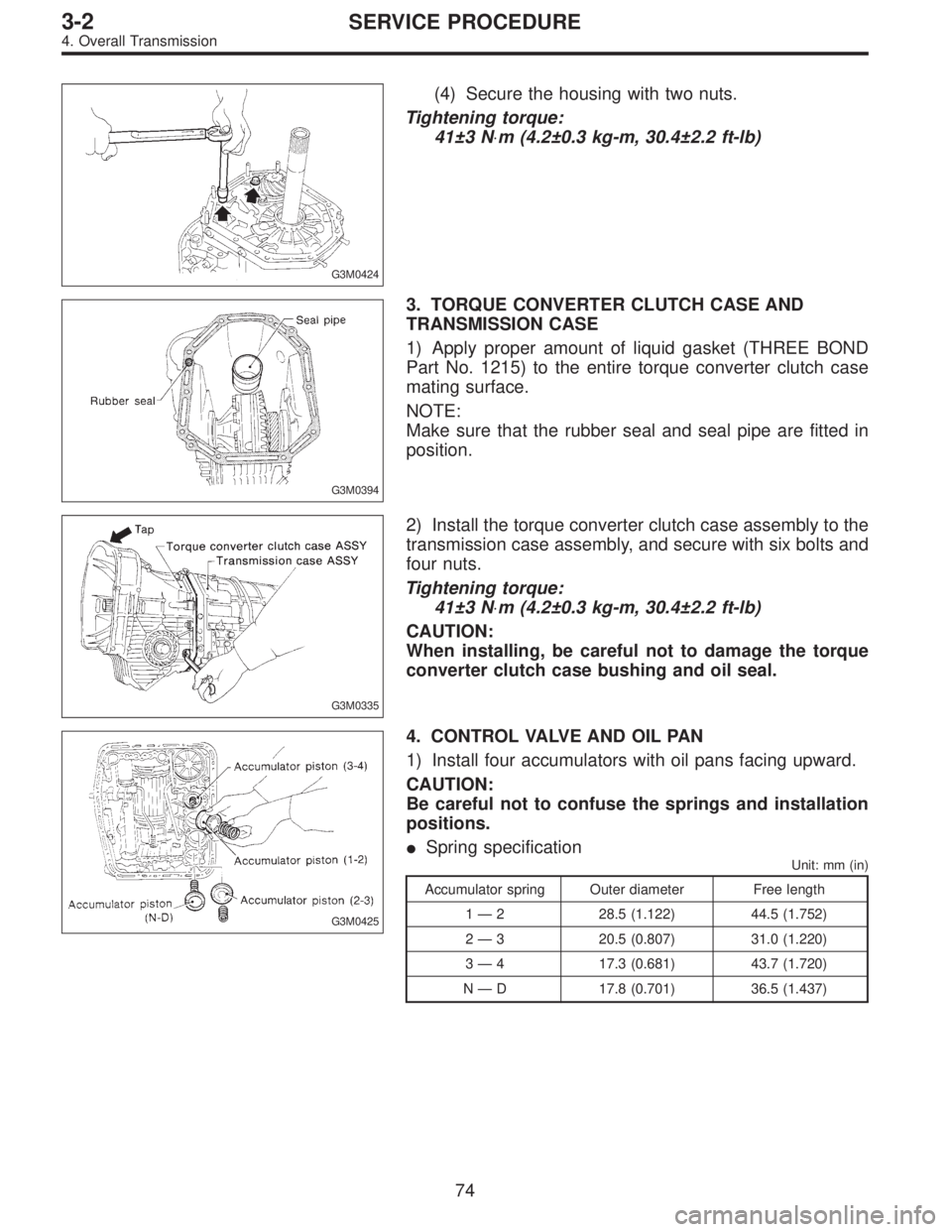
(4) Secure the housing with two nuts.
Tightening torque:
41±3 N⋅m (4.2±0.3 kg-m, 30.4±2.2 ft-lb)
G3M0394
3. TORQUE CONVERTER CLUTCH CASE AND
TRANSMISSION CASE
1) Apply proper amount of liquid gasket (THREE BOND
Part No. 1215) to the entire torque converter clutch case
mating surface.
NOTE:
Make sure that the rubber seal and seal pipe are fitted in
position.
G3M0335
2) Install the torque converter clutch case assembly to the
transmission case assembly, and secure with six bolts and
four nuts.
Tightening torque:
41±3 N⋅m (4.2±0.3 kg-m, 30.4±2.2 ft-lb)
CAUTION:
When installing, be careful not to damage the torque
converter clutch case bushing and oil seal.
G3M0425
4. CONTROL VALVE AND OIL PAN
1) Install four accumulators with oil pans facing upward.
CAUTION:
Be careful not to confuse the springs and installation
positions.
�Spring specification
Unit: mm (in)
Accumulator spring Outer diameter Free length
1—2 28.5 (1.122) 44.5 (1.752)
2—3 20.5 (0.807) 31.0 (1.220)
3—4 17.3 (0.681) 43.7 (1.720)
N—D 17.8 (0.701) 36.5 (1.437)
74
3-2SERVICE PROCEDURE
4. Overall Transmission
Page 912 of 2890

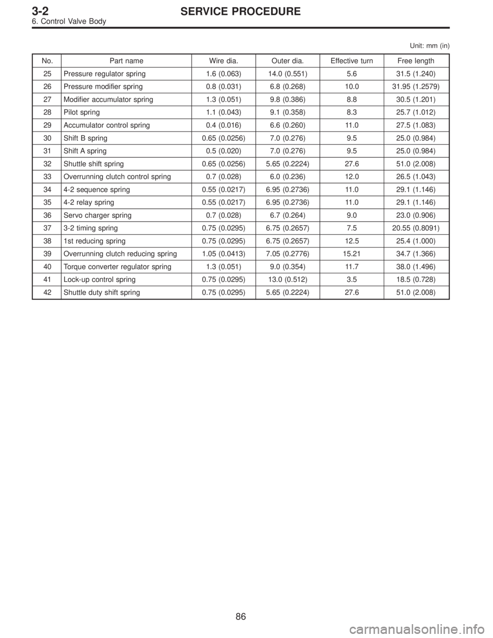
Unit: mm (in)
No. Part name Wire dia. Outer dia. Effective turn Free length
25 Pressure regulator spring 1.6 (0.063) 14.0 (0.551) 5.6 31.5 (1.240)
26 Pressure modifier spring 0.8 (0.031) 6.8 (0.268) 10.0 31.95 (1.2579)
27 Modifier accumulator spring 1.3 (0.051) 9.8 (0.386) 8.8 30.5 (1.201)
28 Pilot spring 1.1 (0.043) 9.1 (0.358) 8.3 25.7 (1.012)
29 Accumulator control spring 0.4 (0.016) 6.6 (0.260) 11.0 27.5 (1.083)
30 Shift B spring 0.65 (0.0256) 7.0 (0.276) 9.5 25.0 (0.984)
31 Shift A spring 0.5 (0.020) 7.0 (0.276) 9.5 25.0 (0.984)
32 Shuttle shift spring 0.65 (0.0256) 5.65 (0.2224) 27.6 51.0 (2.008)
33 Overrunning clutch control spring 0.7 (0.028) 6.0 (0.236) 12.0 26.5 (1.043)
34 4-2 sequence spring 0.55 (0.0217) 6.95 (0.2736) 11.0 29.1 (1.146)
35 4-2 relay spring 0.55 (0.0217) 6.95 (0.2736) 11.0 29.1 (1.146)
36 Servo charger spring 0.7 (0.028) 6.7 (0.264) 9.0 23.0 (0.906)
37 3-2 timing spring 0.75 (0.0295) 6.75 (0.2657) 7.5 20.55 (0.8091)
38 1st reducing spring 0.75 (0.0295) 6.75 (0.2657) 12.5 25.4 (1.000)
39 Overrunning clutch reducing spring 1.05 (0.0413) 7.05 (0.2776) 15.21 34.7 (1.366)
40 Torque converter regulator spring 1.3 (0.051) 9.0 (0.354) 11.7 38.0 (1.496)
41 Lock-up control spring 0.75 (0.0295) 13.0 (0.512) 3.5 18.5 (0.728)
42 Shuttle duty shift spring 0.75 (0.0295) 5.65 (0.2224) 27.6 51.0 (2.008)
86
3-2SERVICE PROCEDURE
6. Control Valve Body
Page 915 of 2890
G3M0906
5) Temporarily assemble lower valve body to upper valve
body.
CAUTION:
Be careful not to drop the upper body interior steel
ball, or the lower body interior filter, orifice check
spring, or orifice check valve.
B3M0406A
6) Install the duty solenoid B and the four brackets.
7) Tighten twenty seven bolts & washers and two reamer
bolts.
Tightening torque:
T1: 8±1 N⋅m (0.8±0.1 kg-m, 5.8±0.7 ft-lb)
T2: 11.3±1.5 N⋅m (1.15±0.15 kg-m, 8.3±1.1 ft-lb)
Unit: mm (in)
abcde
Length 70 (2.76) 50 (1.97) 33 (1.30) 27 (1.06) 28 (1.10)
Numbers 2 6 16 1 2
G3M0864
8) Install the shift solenoid and duty solenoid A.
a length : 16 mm (0.63 in)
b length : 27 mm (1.06 in)
Tightening torque:
8±1 N⋅m (0.8±0.1 kg-m, 5.8±0.7 ft-lb)
G3M0445
7. Oil Pump Assembly
A: DISASSEMBLY
1) Remove the oil seal retainer.
Also remove the O-ring and oil seal (air breather).
89
3-2SERVICE PROCEDURE
6. Control Valve Body - 7. Oil Pump Assembly
Page 916 of 2890
G3M0906
5) Temporarily assemble lower valve body to upper valve
body.
CAUTION:
Be careful not to drop the upper body interior steel
ball, or the lower body interior filter, orifice check
spring, or orifice check valve.
B3M0406A
6) Install the duty solenoid B and the four brackets.
7) Tighten twenty seven bolts & washers and two reamer
bolts.
Tightening torque:
T1: 8±1 N⋅m (0.8±0.1 kg-m, 5.8±0.7 ft-lb)
T2: 11.3±1.5 N⋅m (1.15±0.15 kg-m, 8.3±1.1 ft-lb)
Unit: mm (in)
abcde
Length 70 (2.76) 50 (1.97) 33 (1.30) 27 (1.06) 28 (1.10)
Numbers 2 6 16 1 2
G3M0864
8) Install the shift solenoid and duty solenoid A.
a length : 16 mm (0.63 in)
b length : 27 mm (1.06 in)
Tightening torque:
8±1 N⋅m (0.8±0.1 kg-m, 5.8±0.7 ft-lb)
G3M0445
7. Oil Pump Assembly
A: DISASSEMBLY
1) Remove the oil seal retainer.
Also remove the O-ring and oil seal (air breather).
89
3-2SERVICE PROCEDURE
6. Control Valve Body - 7. Oil Pump Assembly
Page 960 of 2890

B3M0417A
8) Insert the thread portion of the other inner cable end
into the connector hole of the selector lever, and fix the
other outer cable end to the bracket.
9) Adjust the inner cable length.
(1) Put connector into contact with nut�
2.
(2) Tighten nut�
1.
Tightening torque:
7.4±2.0 N⋅m (0.75±0.2 kg-m, 5.4±1.4 ft-lb)
10) After completion of fitting, make sure that the selector
lever operates smoothly all across the operating range.
11) Connect the harnesses and check the following items.
(1) The engine starts operating when selector lever is
in position“P”, but not in other positions.
(2) The back-up light is lit when the selector lever is in
position“R”, but not in other positions.
B3M0348A
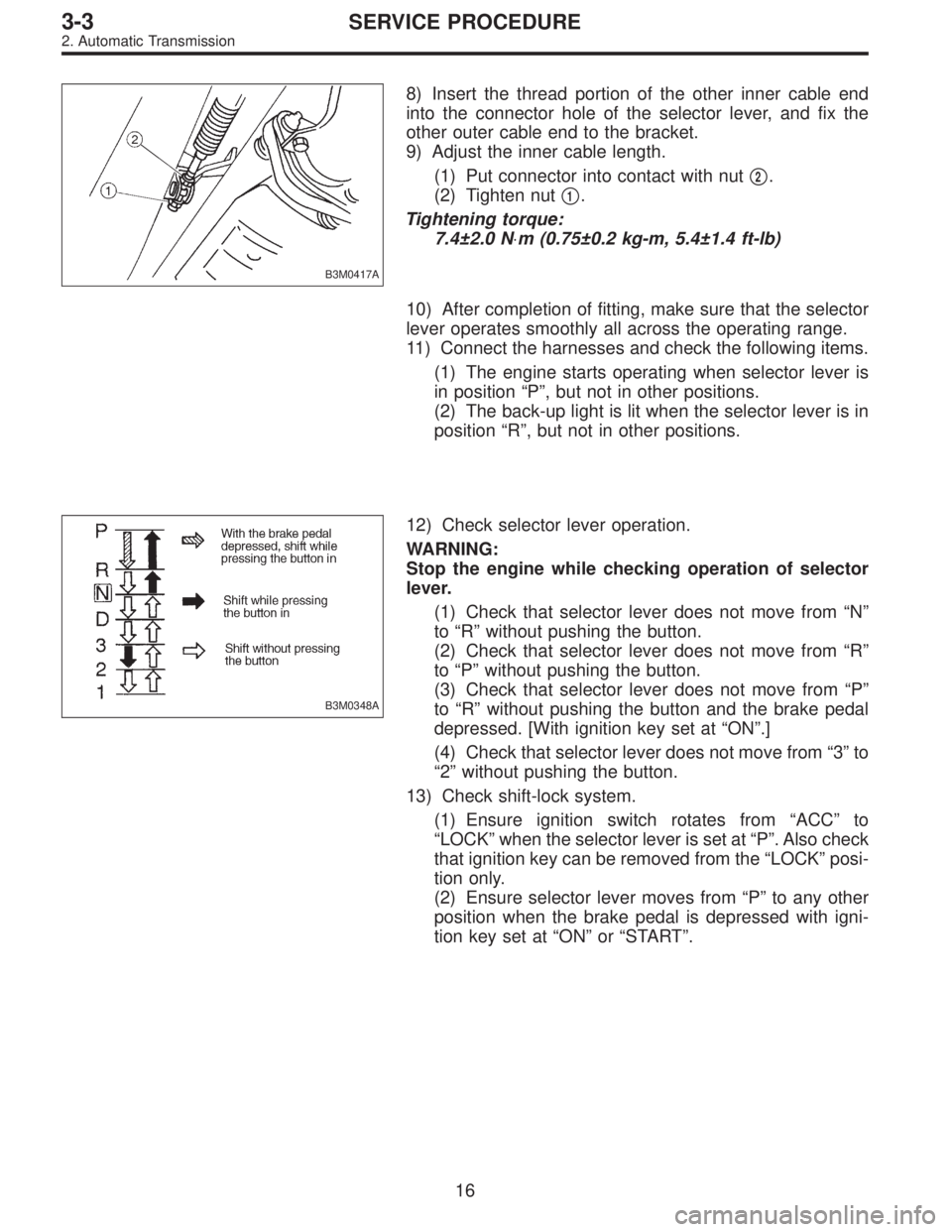
12) Check selector lever operation.
WARNING:
Stop the engine while checking operation of selector
lever.
(1) Check that selector lever does not move from“N”
to“R”without pushing the button.
(2) Check that selector lever does not move from“R”
to“P”without pushing the button.
(3) Check that selector lever does not move from“P”
to“R”without pushing the button and the brake pedal
depressed. [With ignition key set at“ON”.]
(4) Check that selector lever does not move from“3”to
“2”without pushing the button.
13) Check shift-lock system.
(1) Ensure ignition switch rotates from“ACC”to
“LOCK”when the selector lever is set at“P”. Also check
that ignition key can be removed from the“LOCK”posi-
tion only.
(2) Ensure selector lever moves from“P”to any other
position when the brake pedal is depressed with igni-
tion key set at“ON”or“START”.
16
3-3SERVICE PROCEDURE
2. Automatic Transmission
Page 961 of 2890
1. AWD System
A: SPECIFICATIONS
1. REAR FINAL REDUCTION GEAR RATIO
Type of gearHypoid
MT AT
2200 cc*2200 cc
OUTBACK2200 cc 2500 cc
Gear ratio
(Number of
gear teeth)3.900
(39/10)4 . 111
(37/9)4 . 111
(37/9)4.444
(40/9)
Oil capacity 0.8�(0.8 US qt, 0.7 Imp qt)
Rear
differential
gear oilGL-5
*: Step roof model only
2. PROPELLER SHAFT
Front propeller shaft
Joint-to-joint length:
L mm (in)AT 539 (21.22)
MT 598 (23.54)
Outside dia. of tube
mm (in)D
163.5 (2.500)
D
257.0 (2.244)
G3M0014
2
3-4SPECIFICATIONS AND SERVICE DATA
1. AWD System
Page 963 of 2890
C: SERVICE DATA
Front and rear bearing preload at
companion flange bolt holeNew bearing19.6 — 28.4 N
(2.0 — 2.9 kg, 4.4 —6.4 lb)
Used bearing8.34 — 16.67 N
(0.85 — 1.70 kg, 1.87 — 3.75 lb)
Preload adjusting washer lengthPart No. Length
383705200 2.59 mm (0.1020 in)
383715200 2.57 mm (0.1012 in)
383725200 2.55 mm (0.1004 in)
383735200 2.53 mm (0.0996 in)
383745200 2.51 mm (0.0988 in)
383755200 2.49 mm (0.0980 in)
383765200 2.47 mm (0.0972 in)
383775200 2.45 mm (0.0965 in)
383785200 2.43 mm (0.0957 in)
383795200 2.41 mm (0.0949 in)
383805200 2.39 mm (0.0941 in)
383815200 2.37 mm (0.0933 in)
383825200 2.35 mm (0.0925 in)
383835200 2.33 mm (0.0917 in)
383845200 2.31 mm (0.0909 in)
Preload adjusting spacer lengthPart No. Length
383695201 56.2 mm (2.213 in)
383695202 56.4 mm (2.220 in)
383695203 56.6 mm (2.228 in)
383695204 56.8 mm (2.236 in)
383695205 57.0 mm (2.244 in)
383695206 57.2 mm (2.252 in)
4
3-4SPECIFICATIONS AND SERVICE DATA
1. AWD System