Page 295 of 2890
B2M0960
3) Disconnect connector from fuel tank pressure sensor.
4) Remove bolts which install fuel tank pressure sensor
bracket on body.
B2M0961
5) Disconnect hose from fuel tank pressure sensor.
6) Remove fuel tank pressure sensor from bracket.
7) Installation is in the reverse order of removal.
G6M0095
10. Pressure Control Solenoid Valve
(2200 cc AWD Model)
A: REMOVAL AND INSTALLATION
1) Disconnect battery ground cable.
2) Lift-up the vehicle.
B2M0962
3) Disconnect evaporation hoses from pressure control
valve.
4) Disconnect connector from pressure control valve.
B2M0963
5) Remove pressure control valve from bracket.
6) Installation is in the reverse order of removal.
12
2-1SERVICE PROCEDURE
9. Fuel Tank Pressure Sensor (2200 cc AWD Model) - 10. Pressure Control Solenoid Valve (2200 cc AWD Model)
Page 296 of 2890
B2M0960
3) Disconnect connector from fuel tank pressure sensor.
4) Remove bolts which install fuel tank pressure sensor
bracket on body.
B2M0961
5) Disconnect hose from fuel tank pressure sensor.
6) Remove fuel tank pressure sensor from bracket.
7) Installation is in the reverse order of removal.
G6M0095
10. Pressure Control Solenoid Valve
(2200 cc AWD Model)
A: REMOVAL AND INSTALLATION
1) Disconnect battery ground cable.
2) Lift-up the vehicle.
B2M0962
3) Disconnect evaporation hoses from pressure control
valve.
4) Disconnect connector from pressure control valve.
B2M0963
5) Remove pressure control valve from bracket.
6) Installation is in the reverse order of removal.
12
2-1SERVICE PROCEDURE
9. Fuel Tank Pressure Sensor (2200 cc AWD Model) - 10. Pressure Control Solenoid Valve (2200 cc AWD Model)
Page 297 of 2890
G6M0095
11. Vent Control Solenoid Valve (2200
cc AWD Model)
A: REMOVAL
1) Disconnect battery ground cable.
B2M0964
2) Lift-up the vehicle.
3) Remove canister.
4) Disconnect two hoses from air filter.
5) Disconnect connector from vent control solenoid valve.
H2M1469
6) Remove one bolt fixing bracket on the body.
B2M0965A
7) Remove two vacuum hoses from vent control solenoid
valve.
B2M0966
8) Remove one bolt fixing vent control solenoid valve on
bracket.
9) Remove vent control solenoid valve.
13
2-1SERVICE PROCEDURE
11. Vent Control Solenoid Valve (2200 cc AWD Model)
Page 298 of 2890
B2M0966
B: INSTALLATION
1) Install the bolt fixing vent control solenoid valve on
bracket.
B2M0965A
2) Install two vacuum hoses to vent control solenoid valve.
H2M1469
3) Install the bolt fixing bracket on the body.
Tightening torque:
25±7 N⋅m (2.5±0.7 kg-m, 18.1±5.1 ft-lb)
B2M0964
4) Connect connector to vent control solenoid valve.
5) Connect two hoses to air filter.
6) Install canister.
7) Let down the vehicle.
G6M0095
8) Connect battery ground cable.
14
2-1SERVICE PROCEDURE
11. Vent Control Solenoid Valve (2200 cc AWD Model)
Page 299 of 2890
G6M0095
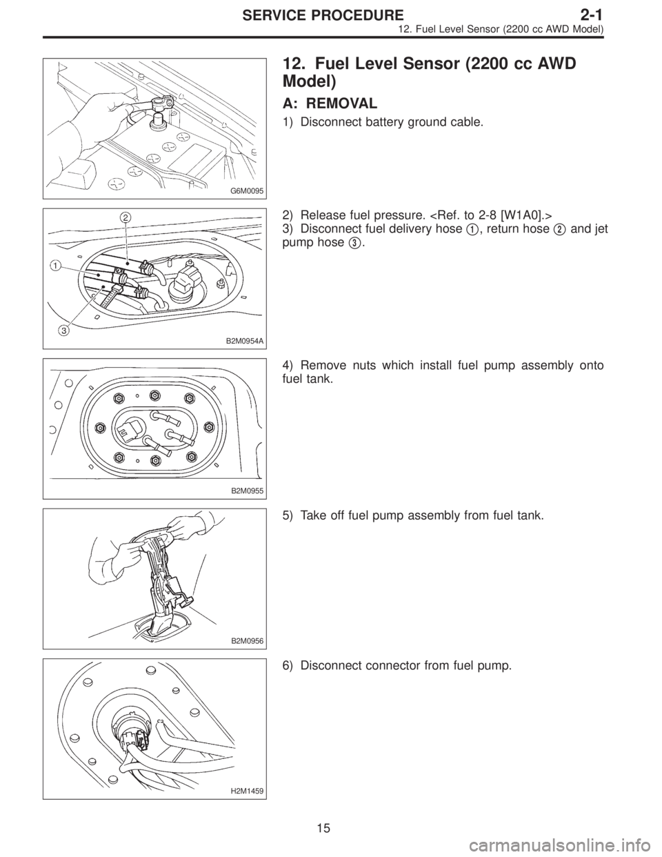
12. Fuel Level Sensor (2200 cc AWD
Model)
A: REMOVAL
1) Disconnect battery ground cable.
B2M0954A
2) Release fuel pressure.
3) Disconnect fuel delivery hose�
1, return hose�2and jet
pump hose�
3.
B2M0955
4) Remove nuts which install fuel pump assembly onto
fuel tank.
B2M0956
5) Take off fuel pump assembly from fuel tank.
H2M1459
6) Disconnect connector from fuel pump.
15
2-1SERVICE PROCEDURE
12. Fuel Level Sensor (2200 cc AWD Model)
Page 300 of 2890
 Remove two screws fixing bracket on fuel pump assem-
bly.
H2M1461A
8) Remove one screw fixing fuel level sensor on bracket.
9) Remove fuel level sensor from fuel pump assembly.
B2M0955A
B:")
H2M1460
7) Remove two screws fixing bracket on fuel pump assem-
bly.
H2M1461A
8) Remove one screw fixing fuel level sensor on bracket.
9) Remove fuel level sensor from fuel pump assembly.
B2M0955A
B: INSTALLATION
CAUTION:
Leave fuel filler cap open when tightening nuts, to pre-
vent fuel from flowing out through fuel delivery and
return pipes. Close fuel filler cap after tightening nuts.
Installation is in the reverse order of removal. Do the fol-
lowing:
(1) Always use new gaskets.
(2) Ensure sealing portion is free from fuel or foreign
particles before installation.
(3) Tighten nuts in numerical sequence shown in Fig-
ure to specified torque.
Tightening torque:
4.4±1.5 N⋅m (0.45±0.15 kg-m, 3.3±1.1 ft-lb)
B2M0968
13. Air Filter (2200 cc AWD Model)
A: REMOVAL AND INSTALLATION
1) Remove canister.
2) Remove two hoses from air filter.
3) Remove flange nut from bracket.
4) Installation is in the reverse order of removal.
16
2-1SERVICE PROCEDURE
12. Fuel Level Sensor (2200 cc AWD Model) - 13. Air Filter (2200 cc AWD Model)
Page 301 of 2890
 Remove two screws fixing bracket on fuel pump assem-
bly.
H2M1461A
8) Remove one screw fixing fuel level sensor on bracket.
9) Remove fuel level sensor from fuel pump assembly.
B2M0955A
B:")
H2M1460
7) Remove two screws fixing bracket on fuel pump assem-
bly.
H2M1461A
8) Remove one screw fixing fuel level sensor on bracket.
9) Remove fuel level sensor from fuel pump assembly.
B2M0955A
B: INSTALLATION
CAUTION:
Leave fuel filler cap open when tightening nuts, to pre-
vent fuel from flowing out through fuel delivery and
return pipes. Close fuel filler cap after tightening nuts.
Installation is in the reverse order of removal. Do the fol-
lowing:
(1) Always use new gaskets.
(2) Ensure sealing portion is free from fuel or foreign
particles before installation.
(3) Tighten nuts in numerical sequence shown in Fig-
ure to specified torque.
Tightening torque:
4.4±1.5 N⋅m (0.45±0.15 kg-m, 3.3±1.1 ft-lb)
B2M0968
13. Air Filter (2200 cc AWD Model)
A: REMOVAL AND INSTALLATION
1) Remove canister.
2) Remove two hoses from air filter.
3) Remove flange nut from bracket.
4) Installation is in the reverse order of removal.
16
2-1SERVICE PROCEDURE
12. Fuel Level Sensor (2200 cc AWD Model) - 13. Air Filter (2200 cc AWD Model)
Page 302 of 2890

1. Foreword
This chapter describes major inspection and service pro-
cedures for the engine mounted on the body. For proce-
dures not found in this chapter, refer to the service proce-
dure section in the applicable chapter.
2. Ignition Timing
A: MEASUREMENT
1. 2200 cc MODEL
1) Warm-up the engine.
G2M0094
2) To check the ignition timing, connect a timing light to #1
cylinder spark plug cord, and illuminate the timing mark
with the timing light.
3) Start the engine at idle speed and check the ignition
timing.
If the timing is not correct, check the ignition control sys-
tem.
Ignition timing [BTDC/rpm]:
14°±8°/700 (MT)
20°±8°/700 (AT)
2. 2500 cc MODEL
CAUTION:
After warming-up, engine becomes very hot. Be care-
ful not to burn yourself during measurement.
1) Warm-up the engine.
B2M0750A
2) To check the ignition timing, connect a timing light to #1
cylinder spark plug cord, and illuminate the timing mark
with the timing light.
3) Start the engine at idle speed and check the ignition
timing.
If the timing is not correct, check the ignition control sys-
tem.
Ignition timing [BTDC/rpm]:
15°±8°/700
2
2-2
1. Foreword - 2. Ignition Timing
 Disconnect connector from fuel tank pressure sensor.
4) Remove bolts which install fuel tank pressure sensor
bracket on body.
B2M0961
5) Disconnect hose from fuel tank pressure sensor.
6) R")
 Disconnect connector from fuel tank pressure sensor.
4) Remove bolts which install fuel tank pressure sensor
bracket on body.
B2M0961
5) Disconnect hose from fuel tank pressure sensor.
6) R")
![SUBARU LEGACY 1996 Service Repair Manual G6M0095
11. Vent Control Solenoid Valve (2200
cc AWD Model)
A: REMOVAL
1) Disconnect battery ground cable.
B2M0964
2) Lift-up the vehicle.
3) Remove canister. <Ref. to 2-1 [W3A2].>
4) Disconnect two h](/manual-img/17/57433/w960_57433-296.png "SUBARU LEGACY 1996 Service Repair Manual G6M0095
11. Vent Control Solenoid Valve (2200
cc AWD Model)
A: REMOVAL
1) Disconnect battery ground cable.
B2M0964
2) Lift-up the vehicle.
3) Remove canister. <Ref. to 2-1 [W3A2].>
4) Disconnect two h")
 Install the bolt fixing vent control solenoid valve on
bracket.
B2M0965A
2) Install two vacuum hoses to vent control solenoid valve.
H2M1469
3) Install the bolt fixing brack")