Page 2494 of 2890
WIRING DIAGRAM:
B4M1035
10M1CHECK IF THE WHEELS HAVE TURNED
FREELY FOR A LONG TIME.
: Check if the wheels have been turned freely
for more than one minute, such as when the
vehicle is jacked-up, under full-lock corner-
ing or when tire is not in contact with road
surface.
: The ABS is normal. Erase the trouble code.
NOTE:
When the wheels turn freely for a long time, such as when
the vehicle is towed or jacked-up, or when steering wheel
is continuously turned all the way, this trouble code may
sometimes occur.
: Go to step10M2.
154
4-4cBRAKES [ABS 5.3 TYPE]
10. Diagnostics Chart with Select Monitor
Page 2495 of 2890
10M2
CHECK TIRE.
: Are the tire specifications correct?
: Go to next.
: Replace tire.
: Is the tire worn excessively?
: Replace tire.
: Go to next.
: Is the tire pressure correct?
: Go to step10M3.
: Adjust tire pressure.
10M3CHECK ABS SENSOR MECHANICAL
TROUBLE.
: Tightening torque:
32±10 N⋅m (3.3±1.0 kg-m, 24±7 ft-lb)
Are the ABS sensor installation bolts tight-
ened securely?
: Go to next.
: Tighten ABS sensor installation bolts securely.
: Tightening torque:
13±3 N⋅m (1.3±0.3 kg-m, 9±2.2 ft-lb)
Are the ABS sensor installation bolts tight-
ened securely?
: Go to next step.
: Tighten ABS sensor installation bolts securely.
G4M0700
1) Measure tone wheel to pole piece gap over entire
perimeter of the wheel.
: Is the gap within the specifications shown
in the following table?
SpecificationsFront wheel Rear wheel
0.9—1.4 mm
(0.035—0.055 in)0.7—1.2 mm
(0.028—0.047 in)
155
4-4cBRAKES [ABS 5.3 TYPE]
10. Diagnostics Chart with Select Monitor
Page 2496 of 2890

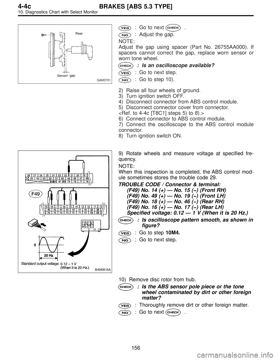
G4M0701
: Go to next.
: Adjust the gap.
NOTE:
Adjust the gap using spacer (Part No. 26755AA000). If
spacers cannot correct the gap, replace worn sensor or
worn tone wheel.
: Is an oscilloscope available?
: Go to next step.
: Go to step 10).
2) Raise all four wheels of ground.
3) Turn ignition switch OFF.
4) Disconnect connector from ABS control module.
5) Disconnect connector cover from connector.
6) Connect connector to ABS control module.
7) Connect the oscilloscope to the ABS control module
connector.
8) Turn ignition switch ON.
B4M0816A
9) Rotate wheels and measure voltage at specified fre-
quency.
NOTE:
When this inspection is completed, the ABS control mod-
ule sometimes stores the trouble code 29.
TROUBLE CODE / Connector & terminal:
(F49) No. 14 (+)—No. 15 (�) (Front RH)
(F49) No. 49 (+)—No. 19 (�) (Front LH)
(F49) No. 18 (+)—No. 46 (�) (Rear RH)
(F49) No. 16 (+)—No. 17 (�) (Rear LH)
Specified voltage: 0.12—1 V (When it is 20 Hz.)
: Is oscilloscope pattern smooth, as shown in
figure?
: Go to step10M4.
: Go to next step.
10) Remove disc rotor from hub.
: Is the ABS sensor pole piece or the tone
wheel contaminated by dirt or other foreign
matter?
: Thoroughly remove dirt or other foreign matter.
: Go to next.
156
4-4cBRAKES [ABS 5.3 TYPE]
10. Diagnostics Chart with Select Monitor
Page 2497 of 2890
: Are there broken or damaged teeth in the
ABS sensor pole piece or the tone wheel?
: Replace ABS sensor or tone wheel.
: Go to next step.
11) Measure hub runout.
: Is the runout less than 0.05 mm (0.0020 in)?
: Go to step10M4.
: Repair hub.
10M4
CHECK ABSCM.
1) Turn ignition switch to OFF.
2) Connect all connectors.
3) Erase the memory.
4) Perform inspection mode.
5) Read out the trouble code.
: Is the same trouble code as in the current
diagnosis still being output?
: Replace ABSCM.
: Go to next.
: Are other trouble codes being output?
: Proceed with the diagnosis corresponding to the
trouble code.
: A temporary poor contact.
157
4-4cBRAKES [ABS 5.3 TYPE]
10. Diagnostics Chart with Select Monitor
Page 2606 of 2890
B4M0813
AK: 56 G SENSOR STICK
—G SENSOR OUTPUT IS STUCK.—
DIAGNOSIS:
�Faulty G sensor output voltage
TROUBLE SYMPTOM:
�ABS does not operate.
10AK1.Check all four wheels for free turning.
10AK2.Check output of G sensor using select
monitor.
�
10AK3.Check poor contact in connector between
ABSCM and G sensor.
10AK4.Check ABSCM.
10AK5.Check broken wire in G sensor output harness
and ground harness.
10AK6.Check G sensor.
10AK7.Check ABSCM.
�
�
�
�
�
266
4-4cBRAKES [ABS 5.3 TYPE]
10. Diagnostics Chart with Select Monitor
Page 2607 of 2890
WIRING DIAGRAM:
B4M1050
10AK1CHECK ALL FOUR WHEELS FOR FREE
TURNING.
: Have the wheels been turned freely such as
when the vehicle is lifted up, or operated on
a rolling road?
: The ABS is normal. Erase the trouble code.
: Go to step10AK2.
B4M0927
10AK2CHECK OUTPUT OF G SENSOR USING
SELECT MONITOR.
1) Press F,1and 0on the select monitor.
2) Read the select monitor display.
: Is the indicated reading 2.3±0.2 V when the
vehicle is in horizontal position?
: Go to next step.
: Go to step10AK5.
267
4-4cBRAKES [ABS 5.3 TYPE]
10. Diagnostics Chart with Select Monitor
Page 2612 of 2890

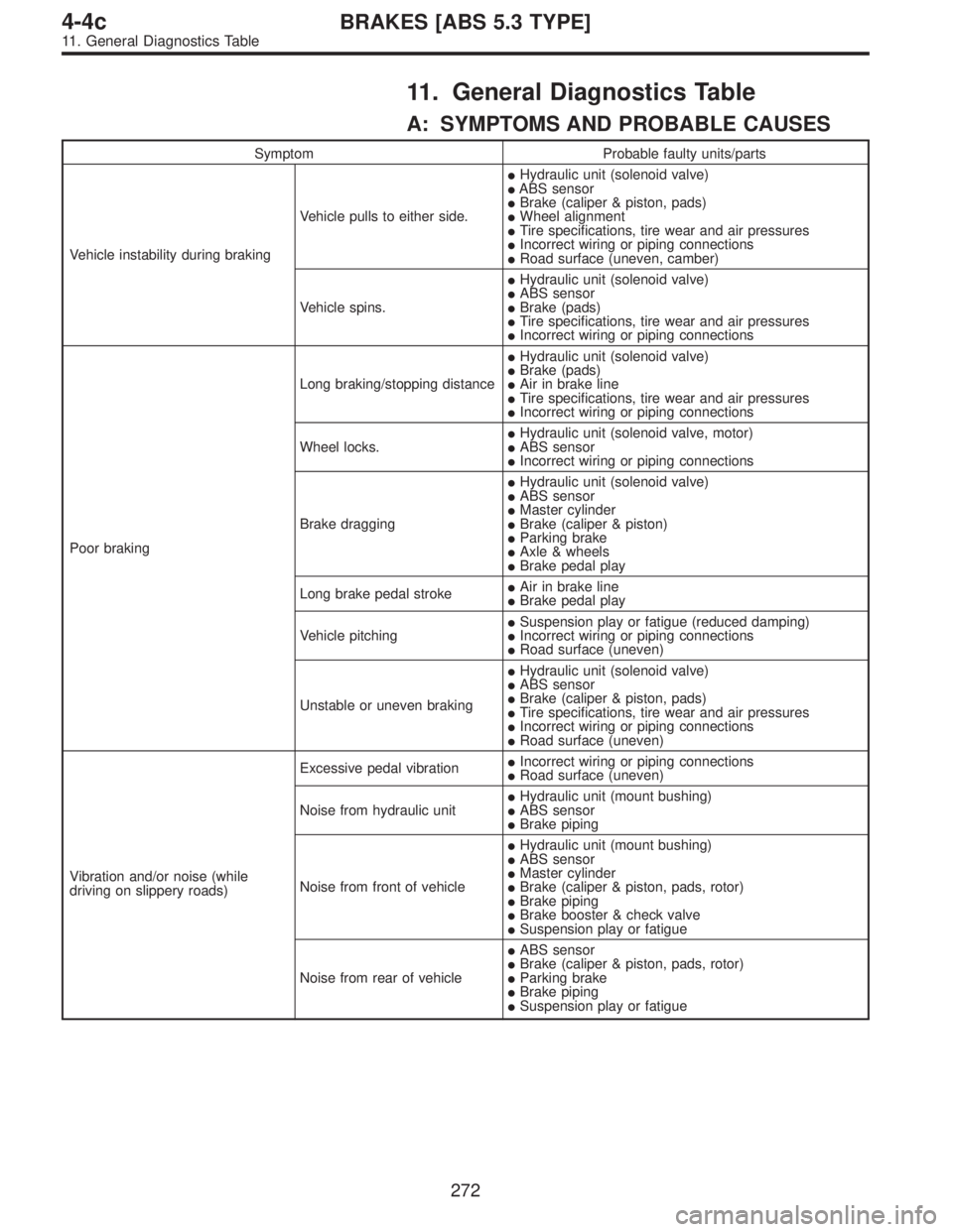
11. General Diagnostics Table
A: SYMPTOMS AND PROBABLE CAUSES
Symptom Probable faulty units/parts
Vehicle instability during brakingVehicle pulls to either side.�Hydraulic unit (solenoid valve)
�ABS sensor
�Brake (caliper & piston, pads)
�Wheel alignment
�Tire specifications, tire wear and air pressures
�Incorrect wiring or piping connections
�Road surface (uneven, camber)
Vehicle spins.�Hydraulic unit (solenoid valve)
�ABS sensor
�Brake (pads)
�Tire specifications, tire wear and air pressures
�Incorrect wiring or piping connections
Poor brakingLong braking/stopping distance�Hydraulic unit (solenoid valve)
�Brake (pads)
�Air in brake line
�Tire specifications, tire wear and air pressures
�Incorrect wiring or piping connections
Wheel locks.�Hydraulic unit (solenoid valve, motor)
�ABS sensor
�Incorrect wiring or piping connections
Brake dragging�Hydraulic unit (solenoid valve)
�ABS sensor
�Master cylinder
�Brake (caliper & piston)
�Parking brake
�Axle & wheels
�Brake pedal play
Long brake pedal stroke�Air in brake line
�Brake pedal play
Vehicle pitching�Suspension play or fatigue (reduced damping)
�Incorrect wiring or piping connections
�Road surface (uneven)
Unstable or uneven braking�Hydraulic unit (solenoid valve)
�ABS sensor
�Brake (caliper & piston, pads)
�Tire specifications, tire wear and air pressures
�Incorrect wiring or piping connections
�Road surface (uneven)
Vibration and/or noise (while
driving on slippery roads)Excessive pedal vibration�Incorrect wiring or piping connections
�Road surface (uneven)
Noise from hydraulic unit�Hydraulic unit (mount bushing)
�ABS sensor
�Brake piping
Noise from front of vehicle�Hydraulic unit (mount bushing)
�ABS sensor
�Master cylinder
�Brake (caliper & piston, pads, rotor)
�Brake piping
�Brake booster & check valve
�Suspension play or fatigue
Noise from rear of vehicle�ABS sensor
�Brake (caliper & piston, pads, rotor)
�Parking brake
�Brake piping
�Suspension play or fatigue
272
4-4cBRAKES [ABS 5.3 TYPE]
11. General Diagnostics Table
Page 2613 of 2890
B: CHECKING THE HYDRAULIC UNIT
OPERATION
1) Do ABS sequence control patterns take place in correct
order?
If not, check wiring and piping for incorrect connections.
2) Are oil pressure or braking force variations within speci-
fications?
If not, check master cylinder, brake piping, hydraulic unit,
proportioning valve and wheel cylinder for improper opera-
tion.
3) Does pedal hardness change before and after ABS
sequence control?
If so, bleed air from brake line.
273
4-4cBRAKES [ABS 5.3 TYPE]
11. General Diagnostics Table