Page 1575 of 2890
G5M0298
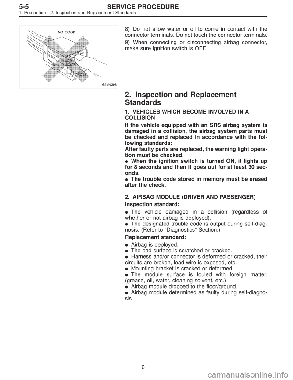
8) Do not allow water or oil to come in contact with the
connector terminals. Do not touch the connector terminals.
9) When connecting or disconnecting airbag connector,
make sure ignition switch is OFF.
2. Inspection and Replacement
Standards
1. VEHICLES WHICH BECOME INVOLVED IN A
COLLISION
If the vehicle equipped with an SRS airbag system is
damaged in a collision, the airbag system parts must
be checked and replaced in accordance with the fol-
lowing standards:
After faulty parts are replaced, the warning light opera-
tion must be checked.
�When the ignition switch is turned ON, it lights up
for 8 seconds and then it goes out for at least 30 sec-
onds.
�The trouble code stored in memory must be erased
after the check.
2. AIRBAG MODULE (DRIVER AND PASSENGER)
Inspection standard:
�The vehicle damaged in a collision (regardless of
whether or not airbag is deployed).
�The designated trouble code is output during self-diag-
nosis. (Refer to“Diagnostics”Section.)
Replacement standard:
�Airbag is deployed.
�The pad surface is scratched or cracked.
�Harness and/or connector is deformed or cracked, their
circuits are broken, lead wire is exposed, etc.
�Mounting bracket is cracked or deformed.
�The module surface is fouled with foreign matter.
(grease, oil, water, cleaning solvent, etc.)
�Airbag module dropped to the floor/ground.
�Airbag module determined as faulty during self-diagno-
sis.
6
5-5SERVICE PROCEDURE
1. Precaution - 2. Inspection and Replacement Standards
Page 1598 of 2890
G5M0298
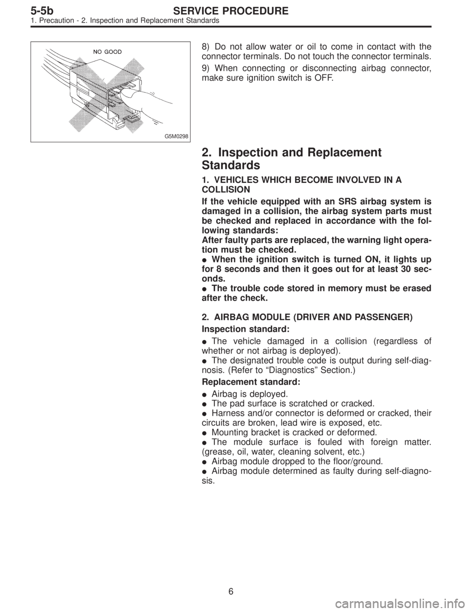
8) Do not allow water or oil to come in contact with the
connector terminals. Do not touch the connector terminals.
9) When connecting or disconnecting airbag connector,
make sure ignition switch is OFF.
2. Inspection and Replacement
Standards
1. VEHICLES WHICH BECOME INVOLVED IN A
COLLISION
If the vehicle equipped with an SRS airbag system is
damaged in a collision, the airbag system parts must
be checked and replaced in accordance with the fol-
lowing standards:
After faulty parts are replaced, the warning light opera-
tion must be checked.
�When the ignition switch is turned ON, it lights up
for 8 seconds and then it goes out for at least 30 sec-
onds.
�The trouble code stored in memory must be erased
after the check.
2. AIRBAG MODULE (DRIVER AND PASSENGER)
Inspection standard:
�The vehicle damaged in a collision (regardless of
whether or not airbag is deployed).
�The designated trouble code is output during self-diag-
nosis. (Refer to“Diagnostics”Section.)
Replacement standard:
�Airbag is deployed.
�The pad surface is scratched or cracked.
�Harness and/or connector is deformed or cracked, their
circuits are broken, lead wire is exposed, etc.
�Mounting bracket is cracked or deformed.
�The module surface is fouled with foreign matter.
(grease, oil, water, cleaning solvent, etc.)
�Airbag module dropped to the floor/ground.
�Airbag module determined as faulty during self-diagno-
sis.
6
5-5bSERVICE PROCEDURE
1. Precaution - 2. Inspection and Replacement Standards
Page 1599 of 2890
G5M0298
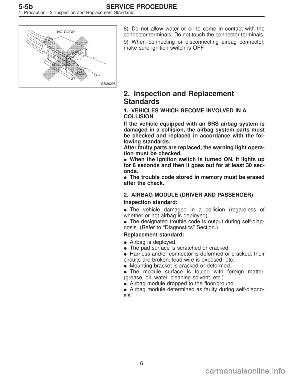
8) Do not allow water or oil to come in contact with the
connector terminals. Do not touch the connector terminals.
9) When connecting or disconnecting airbag connector,
make sure ignition switch is OFF.
2. Inspection and Replacement
Standards
1. VEHICLES WHICH BECOME INVOLVED IN A
COLLISION
If the vehicle equipped with an SRS airbag system is
damaged in a collision, the airbag system parts must
be checked and replaced in accordance with the fol-
lowing standards:
After faulty parts are replaced, the warning light opera-
tion must be checked.
�When the ignition switch is turned ON, it lights up
for 8 seconds and then it goes out for at least 30 sec-
onds.
�The trouble code stored in memory must be erased
after the check.
2. AIRBAG MODULE (DRIVER AND PASSENGER)
Inspection standard:
�The vehicle damaged in a collision (regardless of
whether or not airbag is deployed).
�The designated trouble code is output during self-diag-
nosis. (Refer to“Diagnostics”Section.)
Replacement standard:
�Airbag is deployed.
�The pad surface is scratched or cracked.
�Harness and/or connector is deformed or cracked, their
circuits are broken, lead wire is exposed, etc.
�Mounting bracket is cracked or deformed.
�The module surface is fouled with foreign matter.
(grease, oil, water, cleaning solvent, etc.)
�Airbag module dropped to the floor/ground.
�Airbag module determined as faulty during self-diagno-
sis.
6
5-5bSERVICE PROCEDURE
1. Precaution - 2. Inspection and Replacement Standards
Page 1846 of 2890
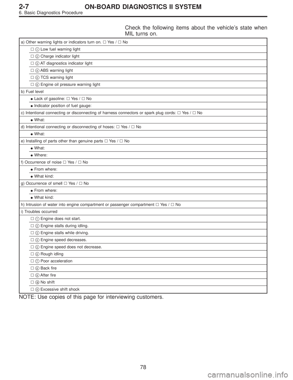
Check the following items about the vehicle’s state when
MIL turns on.
a) Other warning lights or indicators turn on.�Ye s /�No
��
1Low fuel warning light
��
2Charge indicator light
��
3AT diagnostics indicator light
��
4ABS warning light
��
5TCS warning light
��
6Engine oil pressure warning light
b) Fuel level
�Lack of gasoline:�Ye s /�No
�Indicator position of fuel gauge:
c) Intentional connecting or disconnecting of harness connectors or spark plug cords:�Ye s /�No
�What:
d) Intentional connecting or disconnecting of hoses:�Ye s /�No
�What:
e) Installing of parts other than genuine parts�Ye s /�No
�What:
�Where:
f) Occurrence of noise�Ye s /�No
�From where:
�What kind:
g) Occurrence of smell�Ye s /�No
�From where:
�What kind:
h) Intrusion of water into engine compartment or passenger compartment�Ye s /�No
i) Troubles occurred
��
1Engine does not start.
��
2Engine stalls during idling.
��
3Engine stalls while driving.
��
4Engine speed decreases.
��
5Engine speed does not decrease.
��
6Rough idling
��
7Poor acceleration
��
8Back fire
��
9After fire
��
10No shift
��
11Excessive shift shock
NOTE: Use copies of this page for interviewing customers.
78
2-7ON-BOARD DIAGNOSTICS II SYSTEM
6. Basic Diagnostics Procedure
Page 2225 of 2890
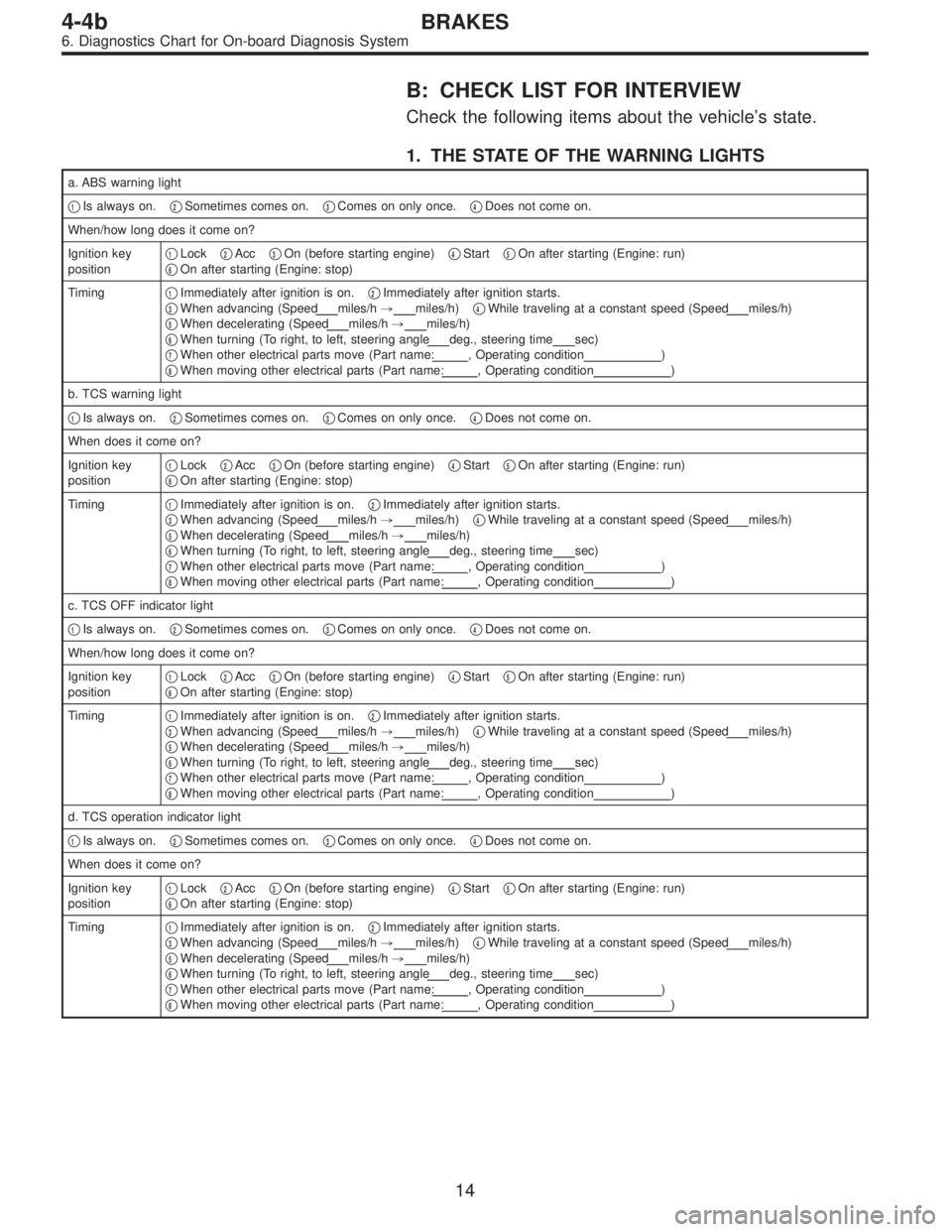
B: CHECK LIST FOR INTERVIEW
Check the following items about the vehicle’s state.
1. THE STATE OF THE WARNING LIGHTS
a. ABS warning light
�
1Is always on.�2Sometimes comes on.�3Comes on only once.�4Does not come on.
When/how long does it come on?
Ignition key
position�
1Lock�2Acc�3On (before starting engine)�4Start�5On after starting (Engine: run)
�6On after starting (Engine: stop)
Timing�
1Immediately after ignition is on.�2Immediately after ignition starts.
�3When advancing (Speedmiles/h,miles/h)�4While traveling at a constant speed (Speedmiles/h)
�5When decelerating (Speedmiles/h,miles/h)
�6When turning (To right, to left, steering angledeg., steering timesec)
�7When other electrical parts move (Part name:, Operating condition)
�8When moving other electrical parts (Part name:, Operating condition)
b. TCS warning light
�
1Is always on.�2Sometimes comes on.�3Comes on only once.�4Does not come on.
When does it come on?
Ignition key
position�
1Lock�2Acc�3On (before starting engine)�4Start�5On after starting (Engine: run)
�6On after starting (Engine: stop)
Timing�
1Immediately after ignition is on.�2Immediately after ignition starts.
�3When advancing (Speedmiles/h,miles/h)�4While traveling at a constant speed (Speedmiles/h)
�5When decelerating (Speedmiles/h,miles/h)
�6When turning (To right, to left, steering angledeg., steering timesec)
�7When other electrical parts move (Part name:, Operating condition)
�8When moving other electrical parts (Part name:, Operating condition)
c. TCS OFF indicator light
�
1Is always on.�2Sometimes comes on.�3Comes on only once.�4Does not come on.
When/how long does it come on?
Ignition key
position�
1Lock�2Acc�3On (before starting engine)�4Start�5On after starting (Engine: run)
�6On after starting (Engine: stop)
Timing�
1Immediately after ignition is on.�2Immediately after ignition starts.
�3When advancing (Speedmiles/h,miles/h)�4While traveling at a constant speed (Speedmiles/h)
�5When decelerating (Speedmiles/h,miles/h)
�6When turning (To right, to left, steering angledeg., steering timesec)
�7When other electrical parts move (Part name:, Operating condition)
�8When moving other electrical parts (Part name:, Operating condition)
d. TCS operation indicator light
�
1Is always on.�2Sometimes comes on.�3Comes on only once.�4Does not come on.
When does it come on?
Ignition key
position�
1Lock�2Acc�3On (before starting engine)�4Start�5On after starting (Engine: run)
�6On after starting (Engine: stop)
Timing�
1Immediately after ignition is on.�2Immediately after ignition starts.
�3When advancing (Speedmiles/h,miles/h)�4While traveling at a constant speed (Speedmiles/h)
�5When decelerating (Speedmiles/h,miles/h)
�6When turning (To right, to left, steering angledeg., steering timesec)
�7When other electrical parts move (Part name:, Operating condition)
�8When moving other electrical parts (Part name:, Operating condition)
14
4-4bBRAKES
6. Diagnostics Chart for On-board Diagnosis System
Page 2231 of 2890
B: ABS AND TCS WARNING LIGHT DO NOT
GO OFF.
—TCS OFF AND TCS OPERATING
INDICATOR LIGHTS COME ON AND GO OFF
PROPERLY WHEN STARTING THE ENGINE,
WHILE ABS WARNING AND TCS WARNING
LIGHTS KEEP ON.—
1. Check brake fluid level.
OK
�Not OK
Add to brake fluid.
2. Check brake fluid level sensor.
OK
�Not OK
Replace master cylinder.
3. Check harness connector between ABS/TCS
control module and alternator.
OK
�Not OK
Replace harness connector.
Replace ABS/TCS control module.
B4M0389
�
�
�
20
4-4bBRAKES
7. Diagnostics Chart for Warning Light Circuit Failure
Page 2233 of 2890
C: TCS WARNING LIGHT AND TCS
INDICATOR OFF AND TCS OPERATING
INDICATOR LIGHTS COME ON AND GO OFF
PROPERLY, WHILE ABS WARNING LIGHT
DOES NOT GO OFF.
—TCS WARNING LIGHT AND TCS OFF
INDICATOR AND TCS OPERATING
INDICATOR LIGHTS COME ON AND GO OFF
PROPERLY WHEN STARTING THE ENGINE,
WHILE ABS WARNING LIGHT DOES NOT GO
OFF.—
1. Check harness connector between ABS/TCS
control module and ABS warning light.�Repair harness connector.
Replace ABS/TCS control module.
B4M0392
�
22
4-4bBRAKES
7. Diagnostics Chart for Warning Light Circuit Failure
Page 2237 of 2890
E: TCS OFF INDICATOR LIGHT DOES NOT
GO OFF.
—ABS WARNING, TCS WARNING AND TCS
OPERATING INDICATOR LIGHTS COME ON
AND GO OFF PROPERLY WHEN STARTING
THE ENGINE, BUT TCS OFF INDICATOR
DOES NOT GO OFF FOR MORE THAN 30
SECONDS AFTER ENGINE RUNNING.—
Does malfunction indicator lamp (Check engine
lamp) come on?
No
�Ye s
Conduct OBD II diagnosis.
1. Check harness connector between ABS/TCS
control module and TCS OFF indicator light.
OK
�Not OK
Repair harness/connector.
Replace ABS/TCS control module.
B4M0396
�
�
26
4-4bBRAKES
7. Diagnostics Chart for Warning Light Circuit Failure