Page 467 of 2890
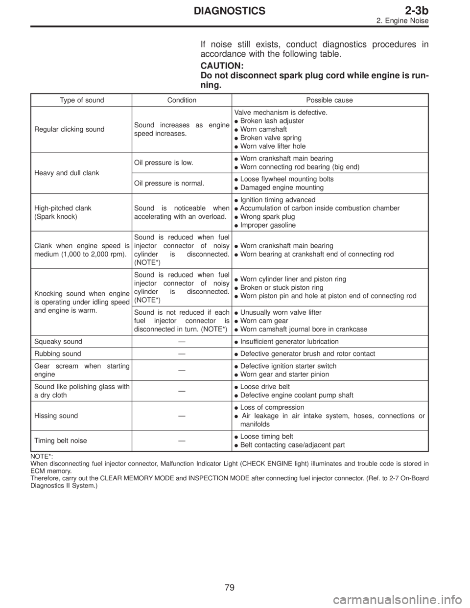
If noise still exists, conduct diagnostics procedures in
accordance with the following table.
CAUTION:
Do not disconnect spark plug cord while engine is run-
ning.
Type of sound Condition Possible cause
Regular clicking soundSound increases as engine
speed increases.Valve mechanism is defective.
�Broken lash adjuster
�Worn camshaft
�Broken valve spring
�Worn valve lifter hole
Heavy and dull clankOil pressure is low.�Worn crankshaft main bearing
�Worn connecting rod bearing (big end)
Oil pressure is normal.�Loose flywheel mounting bolts
�Damaged engine mounting
High-pitched clank
(Spark knock)Sound is noticeable when
accelerating with an overload.�Ignition timing advanced
�Accumulation of carbon inside combustion chamber
�Wrong spark plug
�Improper gasoline
Clank when engine speed is
medium (1,000 to 2,000 rpm).Sound is reduced when fuel
injector connector of noisy
cylinder is disconnected.
(NOTE*)�Worn crankshaft main bearing
�Worn bearing at crankshaft end of connecting rod
Knocking sound when engine
is operating under idling speed
and engine is warm.Sound is reduced when fuel
injector connector of noisy
cylinder is disconnected.
(NOTE*)�Worn cylinder liner and piston ring
�Broken or stuck piston ring
�Worn piston pin and hole at piston end of connecting rod
Sound is not reduced if each
fuel injector connector is
disconnected in turn. (NOTE*)�Unusually worn valve lifter
�Worn cam gear
�Worn camshaft journal bore in crankcase
Squeaky sound—�Insufficient generator lubrication
Rubbing sound—�Defective generator brush and rotor contact
Gear scream when starting
engine—�Defective ignition starter switch
�Worn gear and starter pinion
Sound like polishing glass with
a dry cloth—�Loose drive belt
�Defective engine coolant pump shaft
Hissing sound—�Loss of compression
�Air leakage in air intake system, hoses, connections or
manifolds
Timing belt noise—�Loose timing belt
�Belt contacting case/adjacent part
NOTE*:
When disconnecting fuel injector connector, Malfunction Indicator Light (CHECK ENGINE light) illuminates and trouble code is stored in
ECM memory.
Therefore, carry out the CLEAR MEMORY MODE and INSPECTION MODE after connecting fuel injector connector. (Ref. to 2-7 On-Board
Diagnostics II System.)
79
2-3bDIAGNOSTICS
2. Engine Noise
Page 591 of 2890
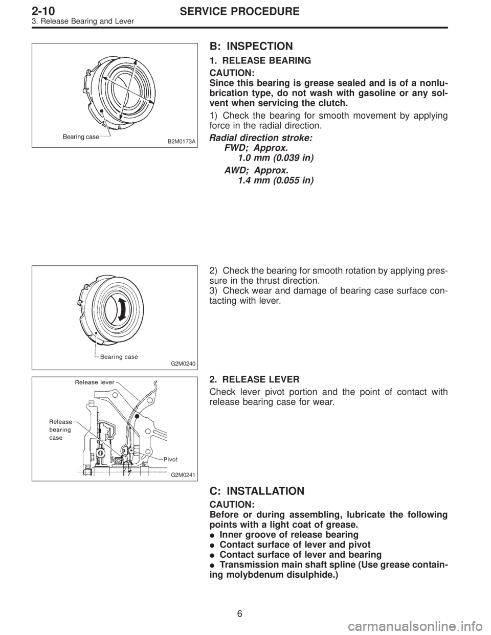
B2M0173A
B: INSPECTION
1. RELEASE BEARING
CAUTION:
Since this bearing is grease sealed and is of a nonlu-
brication type, do not wash with gasoline or any sol-
vent when servicing the clutch.
1) Check the bearing for smooth movement by applying
force in the radial direction.
Radial direction stroke:
FWD; Approx.
1.0 mm (0.039 in)
AWD; Approx.
1.4 mm (0.055 in)
G2M0240
2) Check the bearing for smooth rotation by applying pres-
sure in the thrust direction.
3) Check wear and damage of bearing case surface con-
tacting with lever.
G2M0241
2. RELEASE LEVER
Check lever pivot portion and the point of contact with
release bearing case for wear.
C: INSTALLATION
CAUTION:
Before or during assembling, lubricate the following
points with a light coat of grease.
�Inner groove of release bearing
�Contact surface of lever and pivot
�Contact surface of lever and bearing
�Transmission main shaft spline (Use grease contain-
ing molybdenum disulphide.)
6
2-10SERVICE PROCEDURE
3. Release Bearing and Lever
Page 594 of 2890
G2M0248
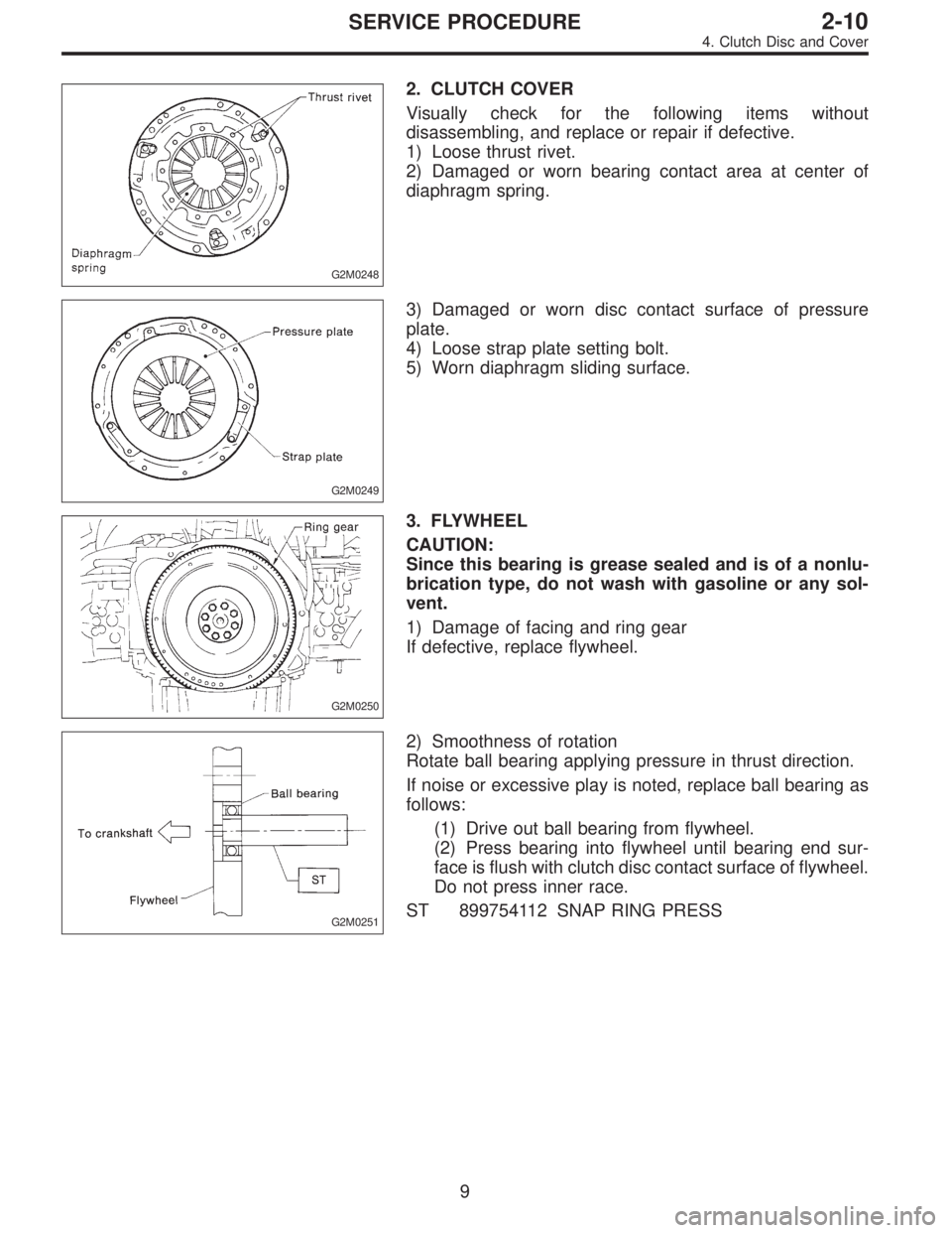
2. CLUTCH COVER
Visually check for the following items without
disassembling, and replace or repair if defective.
1) Loose thrust rivet.
2) Damaged or worn bearing contact area at center of
diaphragm spring.
G2M0249
3) Damaged or worn disc contact surface of pressure
plate.
4) Loose strap plate setting bolt.
5) Worn diaphragm sliding surface.
G2M0250
3. FLYWHEEL
CAUTION:
Since this bearing is grease sealed and is of a nonlu-
brication type, do not wash with gasoline or any sol-
vent.
1) Damage of facing and ring gear
If defective, replace flywheel.
G2M0251
2) Smoothness of rotation
Rotate ball bearing applying pressure in thrust direction.
If noise or excessive play is noted, replace ball bearing as
follows:
(1) Drive out ball bearing from flywheel.
(2) Press bearing into flywheel until bearing end sur-
face is flush with clutch disc contact surface of flywheel.
Do not press inner race.
ST 899754112 SNAP RING PRESS
9
2-10SERVICE PROCEDURE
4. Clutch Disc and Cover
Page 706 of 2890
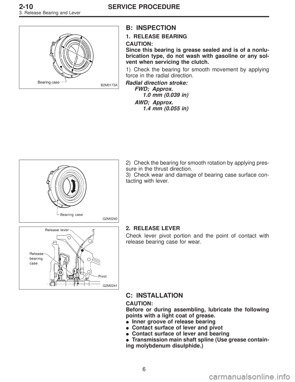
B2M0173A
B: INSPECTION
1. RELEASE BEARING
CAUTION:
Since this bearing is grease sealed and is of a nonlu-
brication type, do not wash with gasoline or any sol-
vent when servicing the clutch.
1) Check the bearing for smooth movement by applying
force in the radial direction.
Radial direction stroke:
FWD; Approx.
1.0 mm (0.039 in)
AWD; Approx.
1.4 mm (0.055 in)
G2M0240
2) Check the bearing for smooth rotation by applying pres-
sure in the thrust direction.
3) Check wear and damage of bearing case surface con-
tacting with lever.
G2M0241
2. RELEASE LEVER
Check lever pivot portion and the point of contact with
release bearing case for wear.
C: INSTALLATION
CAUTION:
Before or during assembling, lubricate the following
points with a light coat of grease.
�Inner groove of release bearing
�Contact surface of lever and pivot
�Contact surface of lever and bearing
�Transmission main shaft spline (Use grease contain-
ing molybdenum disulphide.)
6
2-10SERVICE PROCEDURE
3. Release Bearing and Lever
Page 710 of 2890
G2M0248
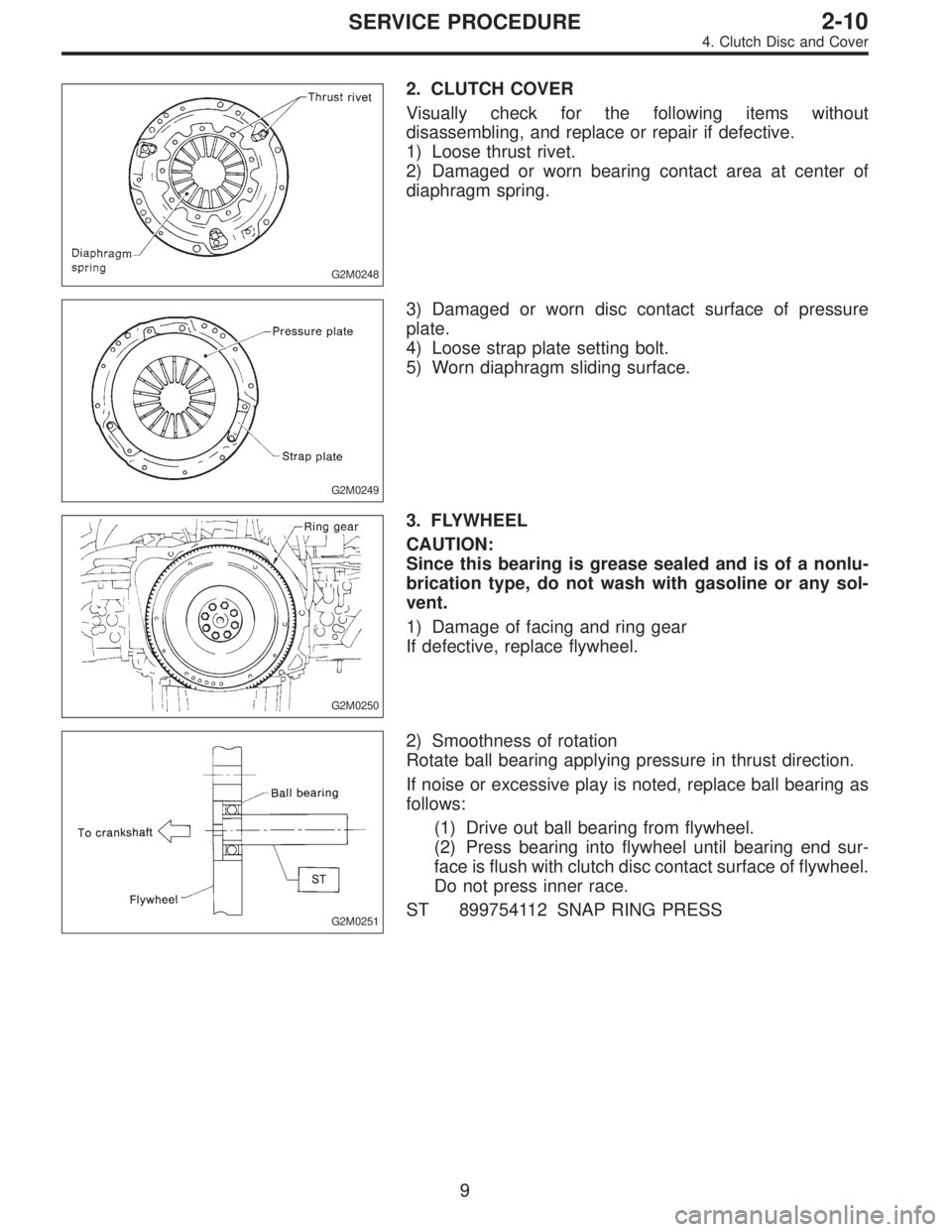
2. CLUTCH COVER
Visually check for the following items without
disassembling, and replace or repair if defective.
1) Loose thrust rivet.
2) Damaged or worn bearing contact area at center of
diaphragm spring.
G2M0249
3) Damaged or worn disc contact surface of pressure
plate.
4) Loose strap plate setting bolt.
5) Worn diaphragm sliding surface.
G2M0250
3. FLYWHEEL
CAUTION:
Since this bearing is grease sealed and is of a nonlu-
brication type, do not wash with gasoline or any sol-
vent.
1) Damage of facing and ring gear
If defective, replace flywheel.
G2M0251
2) Smoothness of rotation
Rotate ball bearing applying pressure in thrust direction.
If noise or excessive play is noted, replace ball bearing as
follows:
(1) Drive out ball bearing from flywheel.
(2) Press bearing into flywheel until bearing end sur-
face is flush with clutch disc contact surface of flywheel.
Do not press inner race.
ST 899754112 SNAP RING PRESS
9
2-10SERVICE PROCEDURE
4. Clutch Disc and Cover
Page 1385 of 2890
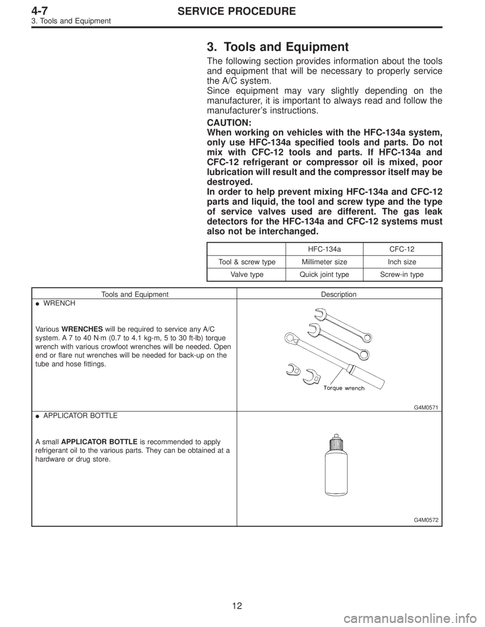
3. Tools and Equipment
The following section provides information about the tools
and equipment that will be necessary to properly service
the A/C system.
Since equipment may vary slightly depending on the
manufacturer, it is important to always read and follow the
manufacturer’s instructions.
CAUTION:
When working on vehicles with the HFC-134a system,
only use HFC-134a specified tools and parts. Do not
mix with CFC-12 tools and parts. If HFC-134a and
CFC-12 refrigerant or compressor oil is mixed, poor
lubrication will result and the compressor itself may be
destroyed.
In order to help prevent mixing HFC-134a and CFC-12
parts and liquid, the tool and screw type and the type
of service valves used are different. The gas leak
detectors for the HFC-134a and CFC-12 systems must
also not be interchanged.
HFC-134a CFC-12
Tool & screw type Millimeter size Inch size
Valve type Quick joint type Screw-in type
Tools and Equipment Description
�WRENCH
VariousWRENCHESwill be required to service any A/C
system. A 7 to 40 N⋅m (0.7 to 4.1 kg-m, 5 to 30 ft-lb) torque
wrench with various crowfoot wrenches will be needed. Open
end or flare nut wrenches will be needed for back-up on the
tube and hose fittings.
G4M0571
�APPLICATOR BOTTLE
A smallAPPLICATOR BOTTLEis recommended to apply
refrigerant oil to the various parts. They can be obtained at a
hardware or drug store.
G4M0572
12
4-7SERVICE PROCEDURE
3. Tools and Equipment
Page 1396 of 2890
8. Leak Testing
The following points should be kept in mind when conduct-
ing a refrigerant leak test.
1) The A/C system to be tested must have an adequate
refrigerant charge to begin with.
2) The area where the leak test is conducted must be free
of wind and drafts, with still air being the ideal condition.
3) The atmosphere where the leak test is conducted must
be free of refrigerant contamination.
4) Operate the A/C system for approx. 10 minutes, then
turn the engine off an begin the leak test.
5) Refrigerant gas is heavier than air, therefore always
hold the probe below the connection being tested.
6) When checking for a leak along a length of hose or
tube, the leak detector probe must be moved slowly,
approx. 25 mm (1 in) per second making sure probe does
not come in contact with the component being tested.
7) When checking for a leak at a certain point, the leak
detector probe must be held at that point for at least 5
seconds.
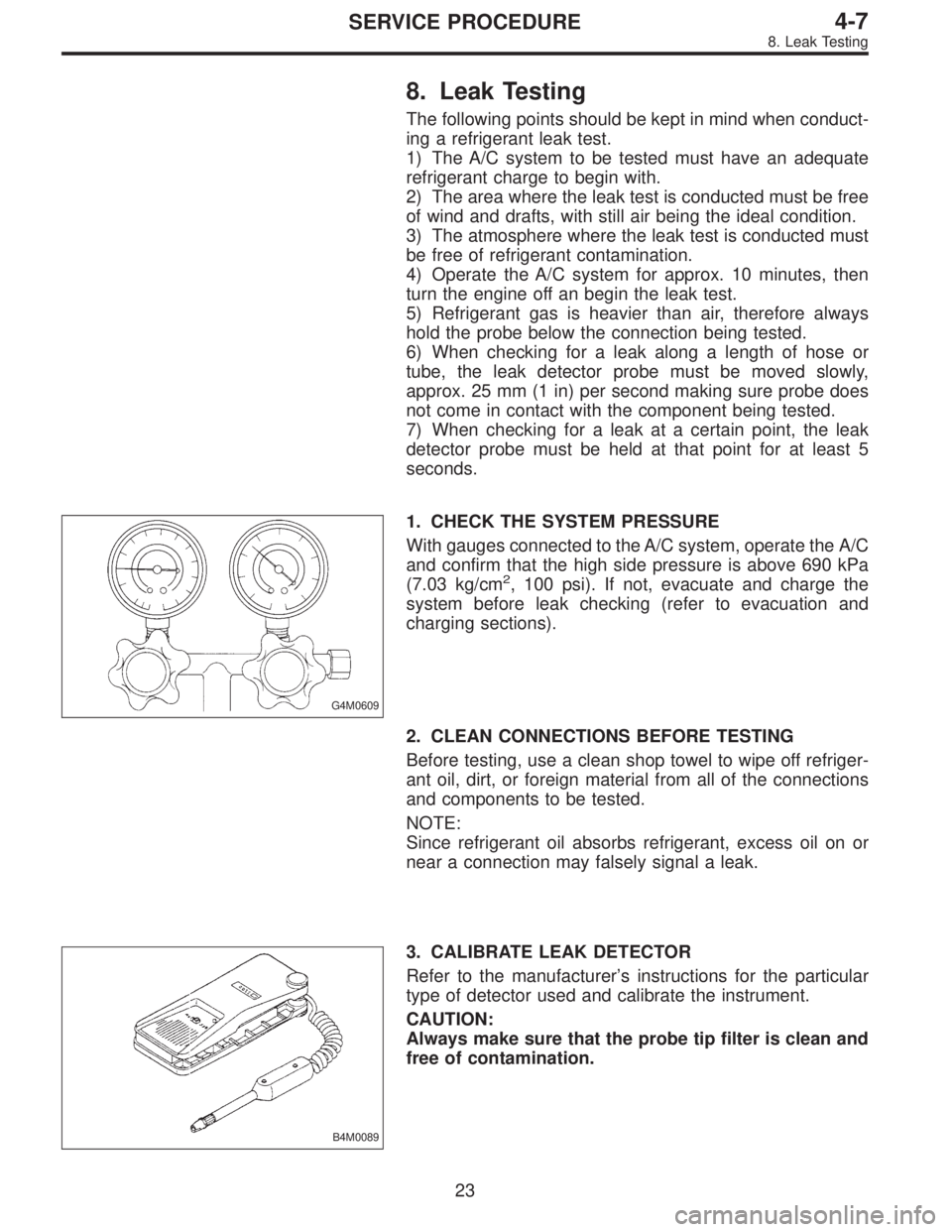
G4M0609
1. CHECK THE SYSTEM PRESSURE
With gauges connected to the A/C system, operate the A/C
and confirm that the high side pressure is above 690 kPa
(7.03 kg/cm
2, 100 psi). If not, evacuate and charge the
system before leak checking (refer to evacuation and
charging sections).
2. CLEAN CONNECTIONS BEFORE TESTING
Before testing, use a clean shop towel to wipe off refriger-
ant oil, dirt, or foreign material from all of the connections
and components to be tested.
NOTE:
Since refrigerant oil absorbs refrigerant, excess oil on or
near a connection may falsely signal a leak.
B4M0089
3. CALIBRATE LEAK DETECTOR
Refer to the manufacturer’s instructions for the particular
type of detector used and calibrate the instrument.
CAUTION:
Always make sure that the probe tip filter is clean and
free of contamination.
23
4-7SERVICE PROCEDURE
8. Leak Testing
Page 1663 of 2890
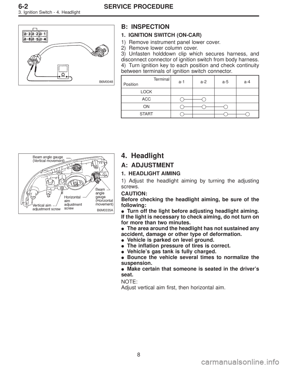
B6M0048
B: INSPECTION
1. IGNITION SWITCH (ON-CAR)
1) Remove instrument panel lower cover.
2) Remove lower column cover.
3) Unfasten holddown clip which secures harness, and
disconnect connector of ignition switch from body harness.
4) Turn ignition key to each position and check continuity
between terminals of ignition switch connector.
Terminal
Positiona-1 a-2 a-5 a-4
LOCK
ACC��
ON���
START���
B6M0335A
4. Headlight
A: ADJUSTMENT
1. HEADLIGHT AIMING
1) Adjust the headlight aiming by turning the adjusting
screws.
CAUTION:
Before checking the headlight aiming, be sure of the
following:
�Turn off the light before adjusting headlight aiming.
If the light is necessary to check aiming, do not turn on
for more than two minutes.
�The area around the headlight has not sustained any
accident, damage or other type of deformation.
�Vehicle is parked on level ground.
�The inflation pressure of tires is correct.
�Vehicle’s gas tank is fully charged.
�Bounce the vehicle several times to normalize the
suspension.
�Make certain that someone is seated in the driver’s
seat.
NOTE:
Adjust vertical aim first, then horizontal aim.
8
6-2SERVICE PROCEDURE
3. Ignition Switch - 4. Headlight