Page 476 of 2890
G2M0066
9) Drain engine oil.
Set container under the vehicle, and remove drain plug
from oil pan.
B2M0312
10) Disconnect connector from rear oxygen sensor.
(Except California 2200 cc model)
B2M0054
11) Remove front exhaust pipe.
(1) Separate front catalytic converter from center
exhaust pipe.
(2) Remove front exhaust pipe from engine.
(3) Remove bolt which installs front exhaust pipe on
bracket.
B2M0743A
12) Remove nuts which install front cushion rubber onto
front crossmember.
G2M0081
13) Remove bolts which install oil pan on cylinder block
while raising up engine.
14) Insert oil pan cutter blade between cylinder block-to-oil
pan clearance.
CAUTION:
Do not use a screwdriver or similar tool in place of oil
pan cutter.
10
2-4SERVICE PROCEDURE
2. Oil Pan and Oil Strainer
Page 479 of 2890
B2M0054
9) Install front exhaust pipe.
CAUTION:
Always use the new gaskets.
(1) Place front exhaust pipe on bracket.
(2) Tighten nuts which install front exhaust pipe on
engine.
Tightening torque:
30±5 N⋅m (3.1±0.5 kg-m, 22.4±3.6 ft-lb)
B2M0055
(3) Tighten nuts which install front catalytic converter to
center exhaust pipe.
Tightening torque:
35±5 N⋅m (3.6±0.5 kg-m, 26.0±3.6 ft-lb)
B2M0056
(4) Tighten bolt which installs front exhaust pipe on
bracket.
Tightening torque:
24±3 N⋅m (2.4±0.3 kg-m, 17.4±2.2 ft-lb)
B2M0312
10) Connect connector to rear oxygen sensor. (Except
California 2200 cc model)
B2M0053
11) Lower the vehicle.
CAUTION:
At this time, lower lifting device and release steel
cables.
12) Remove lifting device and steel cables.
13
2-4SERVICE PROCEDURE
2. Oil Pan and Oil Strainer
Page 578 of 2890
1. Exhaust System
1. 2500 cc MODEL
B2M0311A
�1Upper front exhaust pipe cover CTR
�
2Lower front exhaust pipe cover CTR
�
3Band RH
�
4Band LH
�
5Upper front exhaust pipe cover LH
�
6Lower front exhaust pipe cover LH
�
7Front exhaust pipe
�
8Lower front exhaust pipe cover RH
�
9Upper front exhaust pipe cover RH
�
10Gasket
�
11Spring
�
12Rear exhaust pipe�
13Self-locking nut
�
14Gasket
�
15Muffler
�
16Cushion rubber
�
17Clamp
�
18Upper center exhaust pipe cover
�
19Center exhaust pipe
�
20Clamp B
�
21Upper rear catalytic converter cover
�
22Lower rear catalytic converter cover
�
23Gasket
�
24Front oxygen sensor�
25Rear oxygen sensor
�
26Front catalytic converter
�
27Lower front catalytic converter cover
�
28Upper front catalytic converter cover
Tightening torque: N⋅m (kg-m, ft-lb)
T1: 13±3 (1.3±0.3, 9.4±2.2)
T2: 18±5 (1.8±0.5, 13.0±3.6)
T3: 30±5 (3.1±0.5, 22.4±3.6)
T4: 35±5 (3.6±0.5, 26.0±3.6)
T5: 48±5 (4.9±0.5, 35.4±3.6)
2
2-9COMPONENT PARTS
1. Exhaust System
Page 579 of 2890

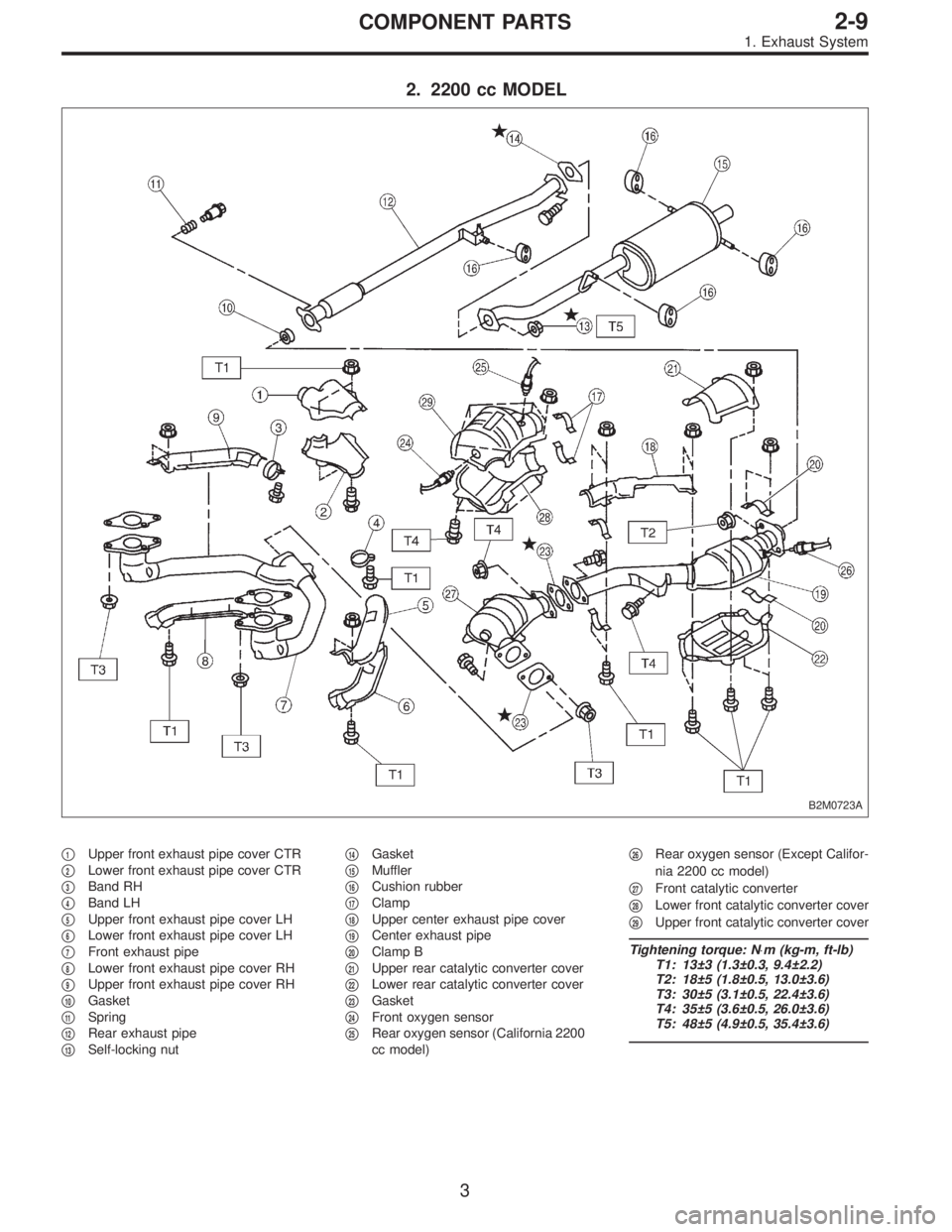
2. 2200 cc MODEL
B2M0723A
�1Upper front exhaust pipe cover CTR
�
2Lower front exhaust pipe cover CTR
�
3Band RH
�
4Band LH
�
5Upper front exhaust pipe cover LH
�
6Lower front exhaust pipe cover LH
�
7Front exhaust pipe
�
8Lower front exhaust pipe cover RH
�
9Upper front exhaust pipe cover RH
�
10Gasket
�
11Spring
�
12Rear exhaust pipe
�
13Self-locking nut�
14Gasket
�
15Muffler
�
16Cushion rubber
�
17Clamp
�
18Upper center exhaust pipe cover
�
19Center exhaust pipe
�
20Clamp B
�
21Upper rear catalytic converter cover
�
22Lower rear catalytic converter cover
�
23Gasket
�
24Front oxygen sensor
�
25Rear oxygen sensor (California 2200
cc model)�
26Rear oxygen sensor (Except Califor-
nia 2200 cc model)
�
27Front catalytic converter
�
28Lower front catalytic converter cover
�
29Upper front catalytic converter cover
Tightening torque: N⋅m (kg-m, ft-lb)
T1: 13±3 (1.3±0.3, 9.4±2.2)
T2: 18±5 (1.8±0.5, 13.0±3.6)
T3: 30±5 (3.1±0.5, 22.4±3.6)
T4: 35±5 (3.6±0.5, 26.0±3.6)
T5: 48±5 (4.9±0.5, 35.4±3.6)
3
2-9COMPONENT PARTS
1. Exhaust System
Page 581 of 2890
B2M0313
7) Remove front exhaust pipe and center exhaust pipe
from hanger bracket.
CAUTION:
Be careful not to pull down front exhaust pipe and
center exhaust pipe.
B2M0060
8) Separate front exhaust pipe from front catalytic con-
verter.
B2M0060
B: INSTALLATION
CAUTION:
Replace gaskets with new ones.
1) Install front catalytic converter to front exhaust pipe.
Tightening torque:
30±5 N⋅m (3.1±0.5 kg-m, 22.4±3.6 ft-lb)
B2M0313
2) Install front exhaust pipe and center exhaust pipe.
And temporarily tighten bolt which installs center exhaust
pipe to hanger bracket.
B2M0054
3) Tighten bolts which hold front exhaust pipe onto cylin-
der heads.
Tightening torque:
30±5 N⋅m (3.1±0.5 kg-m, 22.4±3.6 ft-lb)
5
2-9SERVICE PROCEDURE
1. Front Exhaust Pipe and Center Exhaust Pipe
Page 692 of 2890
1. Exhaust System
1. 2500 cc MODEL
B2M0311A
�1Upper front exhaust pipe cover CTR
�
2Lower front exhaust pipe cover CTR
�
3Band RH
�
4Band LH
�
5Upper front exhaust pipe cover LH
�
6Lower front exhaust pipe cover LH
�
7Front exhaust pipe
�
8Lower front exhaust pipe cover RH
�
9Upper front exhaust pipe cover RH
�
10Gasket
�
11Spring
�
12Rear exhaust pipe�
13Self-locking nut
�
14Gasket
�
15Muffler
�
16Cushion rubber
�
17Clamp
�
18Upper center exhaust pipe cover
�
19Center exhaust pipe
�
20Clamp B
�
21Upper rear catalytic converter cover
�
22Lower rear catalytic converter cover
�
23Gasket
�
24Front oxygen sensor�
25Rear oxygen sensor
�
26Front catalytic converter
�
27Lower front catalytic converter cover
�
28Upper front catalytic converter cover
Tightening torque: N⋅m (kg-m, ft-lb)
T1: 13±3 (1.3±0.3, 9.4±2.2)
T2: 18±5 (1.8±0.5, 13.0±3.6)
T3: 30±5 (3.1±0.5, 22.4±3.6)
T4: 35±5 (3.6±0.5, 26.0±3.6)
T5: 48±5 (4.9±0.5, 35.4±3.6)
2
2-9COMPONENT PARTS
1. Exhaust System
Page 693 of 2890

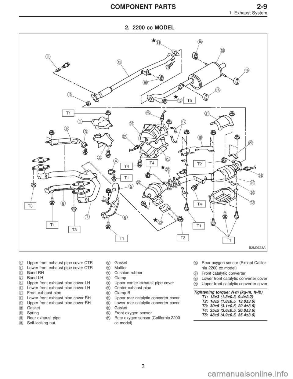
2. 2200 cc MODEL
B2M0723A
�1Upper front exhaust pipe cover CTR
�
2Lower front exhaust pipe cover CTR
�
3Band RH
�
4Band LH
�
5Upper front exhaust pipe cover LH
�
6Lower front exhaust pipe cover LH
�
7Front exhaust pipe
�
8Lower front exhaust pipe cover RH
�
9Upper front exhaust pipe cover RH
�
10Gasket
�
11Spring
�
12Rear exhaust pipe
�
13Self-locking nut�
14Gasket
�
15Muffler
�
16Cushion rubber
�
17Clamp
�
18Upper center exhaust pipe cover
�
19Center exhaust pipe
�
20Clamp B
�
21Upper rear catalytic converter cover
�
22Lower rear catalytic converter cover
�
23Gasket
�
24Front oxygen sensor
�
25Rear oxygen sensor (California 2200
cc model)�
26Rear oxygen sensor (Except Califor-
nia 2200 cc model)
�
27Front catalytic converter
�
28Lower front catalytic converter cover
�
29Upper front catalytic converter cover
Tightening torque: N⋅m (kg-m, ft-lb)
T1: 13±3 (1.3±0.3, 9.4±2.2)
T2: 18±5 (1.8±0.5, 13.0±3.6)
T3: 30±5 (3.1±0.5, 22.4±3.6)
T4: 35±5 (3.6±0.5, 26.0±3.6)
T5: 48±5 (4.9±0.5, 35.4±3.6)
3
2-9COMPONENT PARTS
1. Exhaust System
Page 695 of 2890
B2M0313
7) Remove front exhaust pipe and center exhaust pipe
from hanger bracket.
CAUTION:
Be careful not to pull down front exhaust pipe and
center exhaust pipe.
B2M0060
8) Separate front exhaust pipe from front catalytic con-
verter.
B2M0060
B: INSTALLATION
CAUTION:
Replace gaskets with new ones.
1) Install front catalytic converter to front exhaust pipe.
Tightening torque:
30±5 N⋅m (3.1±0.5 kg-m, 22.4±3.6 ft-lb)
B2M0313
2) Install front exhaust pipe and center exhaust pipe.
And temporarily tighten bolt which installs center exhaust
pipe to hanger bracket.
B2M0054
3) Tighten bolts which hold front exhaust pipe onto cylin-
der heads.
Tightening torque:
30±5 N⋅m (3.1±0.5 kg-m, 22.4±3.6 ft-lb)
5
2-9SERVICE PROCEDURE
1. Front Exhaust Pipe and Center Exhaust Pipe