Page 217 of 2890

2-7
trsi31
ON-BOARD
DIAGNOSTICS
II
SYSTEM
8
.
Diagnostics
for
Engine
Starting
Failure
R58
Bog
1
23
2
1
L
11
5
643
D
S2
B2M0526A
,rES
:
Go
to
step
813
.
No
:
Repair
open
circuit
in
fuel
pump
ground
circuit
.
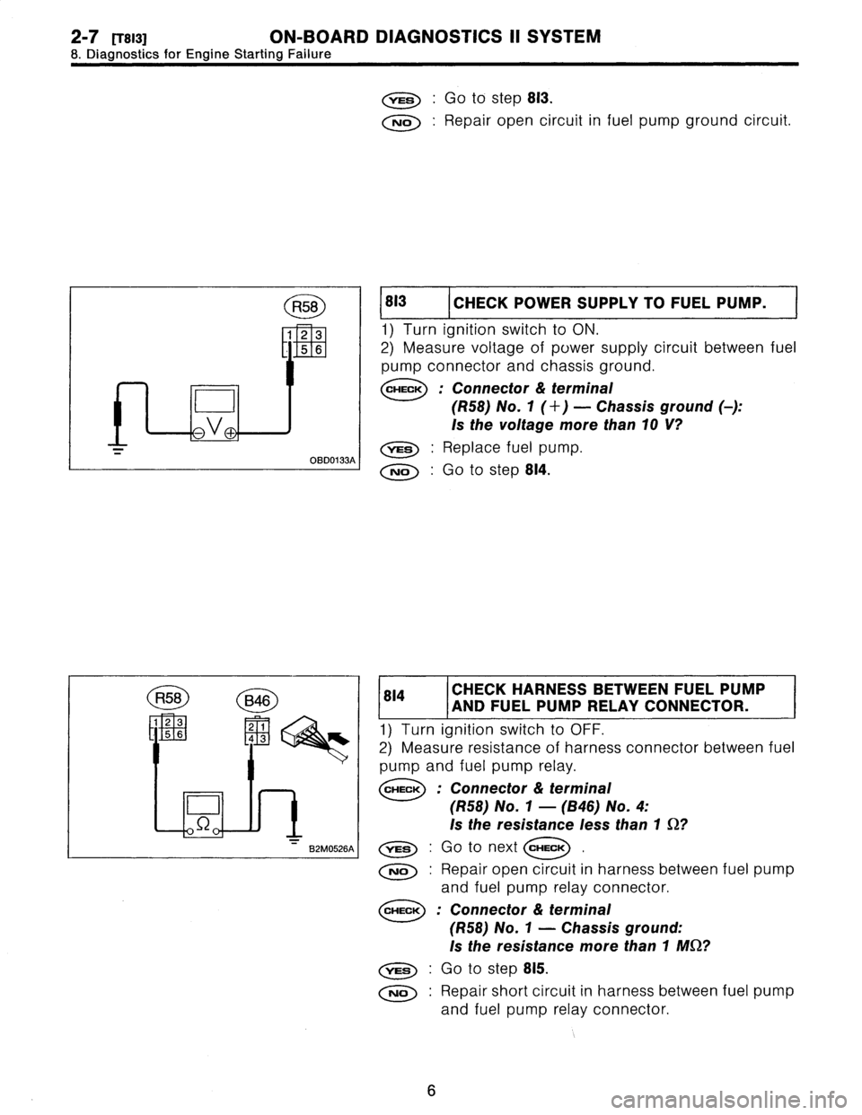
813
I
CHECK
POWER
SUPPLY
TOFUEL
PUMP
.
1)
Turn
ignition
switch
to
ON
.
2)
Measure
voltage
of
power
supply
circuit
between
fuel
pump
connector
and
chassis
ground
.
CHECK
:
Connector
&
terminal
(R58)
No
.
1
(+)
-
Chassis
ground
(
)
:
Is
the
voltage
more
than10
V?
,rES
:
Replace
fuel
pump
.
No
:
Go
to
step
814
.
814
CHECK
HARNESS
BETWEEN
FUEL
PUMP
AND
FUEL
PUMP
RELAY
CONNECTOR
.
1)
Turn
ignition
switch
to
OFF
.
2)
Measure
resistance
of
harness
connector
between
fuel
pump
and
fuel
pump
relay
.
CHECK
:
Connector
&
terminal
(R58)
No
.
1
-
(B46)
No
.
4
:
Is
the
resistance
less
than
1
S2?
,rES
:
Go
to
next
CHECK
No
:
Repair
open
circuit
in
harness
between
fuel
pump
and
fuel
pump
relay
connector
.
CHECK
:
Connector
&
terminal
(R58)
No
.
1
-
Chassis
ground
:
Is
the
resistance
more
than
1
MS2?
,res
:
Go
to
step
815
.
No
:
Repair
short
circuit
in
harness
between
fuel
pump
and
fuel
pump
relay
connector
.
6
Page 225 of 2890

2-7
RyoBOa1
ON-BOARD
DIAGNOSTICS
i1
SYSTEM
10
.
Diagnostics
Chart
with
Trouble
Code
R58
D
~,V
P
B2M0917A
I
R58
B2M0918A
I
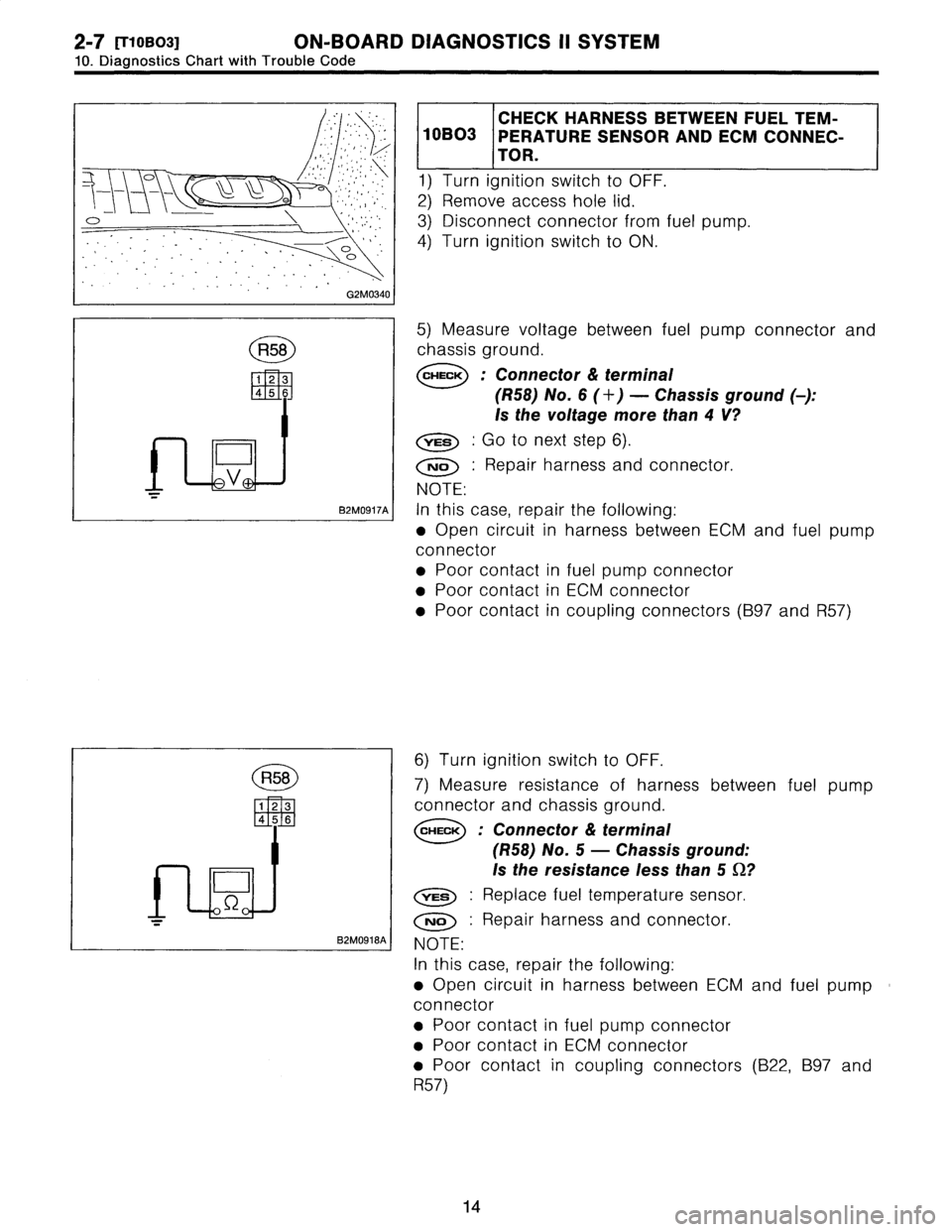
CHECK
HARNESSBETWEEN
FUELTEM-
10B03
PERATURE
SENSOR
AND
ECM
CONNEC-
TOR
.
1)
Turn
ignition
switch
to
OFF
.
2)
Remove
access
hole
lid
.
3)
Disconnect
connector
from
fuel
pump
.
4)
Turn
ignition
switch
to
ON
.
5)
Measure
voltage
between
fuel
pump
connector
and
chassis
ground
.
CHECK
:
Connector
&
terminal
(R58)
No
.
6
(+)
-
Chassis
ground
(
)
:
Is
thevoltage
more
than4V?
YES
:
Go
to
next
step
6)
.
No
:
Repair
harness
and
connector
.
NOTE
:
In
this
case,
repair
the
following
:
*
Open
circuit
in
harness
between
ECM
and
fuel
pump
connector
"
Poor
contact
in
fuel
pump
connector
"
Poor
contact
in
ECM
connector
"
Poor
contact
in
coupling
connectors(B97
and
R57)
6)
Turn
ignition
switch
to
OFF
.
7)
Measure
resistance
of
harness
between
fuel
pump
connector
and
chassis
ground
.
CHECK
:
Connector
&
terminal
(R58)
No
.
5
-
Chassi
Is
the
resistance
less
,rES
:
Replace
fuel
temperatur
No
:
Repair
harness
andcon
NOTE
:
In
this
case,
repair
the
following
9
Open
circuit
in
harness
betw
e
connector
"
Poor
contact
in
fuel
pump
co
"
Poor
contact
in
ECM
connect
"
Poor
contact
in
coupling
co
R57)
14
s
ground
:
than5
S~?
e
sensor
.
nector
.
en
ECM
and
fuel
pump
nnector
or
nnectors
(B22,
B97
and
Page 235 of 2890
![SUBARU LEGACY 1996 Service Repair Manual 2_7
[T10BR1]
ON-BOARD
DIAGNOSTICS
II
SYSTEM
10
.
Diagnostics
Chart
with
Trouble
Code
D
H2M1238A
I
1
10BR1
I
CHECK
OUTPUT
SIGNAL
FROM
ECM
.
1)
Turn
ignition
switch
to
ON
.
2)
Measure
voltage
betw SUBARU LEGACY 1996 Service Repair Manual 2_7
[T10BR1]
ON-BOARD
DIAGNOSTICS
II
SYSTEM
10
.
Diagnostics
Chart
with
Trouble
Code
D
H2M1238A
I
1
10BR1
I
CHECK
OUTPUT
SIGNAL
FROM
ECM
.
1)
Turn
ignition
switch
to
ON
.
2)
Measure
voltage
betw](/manual-img/17/57433/w960_57433-234.png)
2_7
[T10BR1]
ON-BOARD
DIAGNOSTICS
II
SYSTEM
10
.
Diagnostics
Chart
with
Trouble
Code
D
H2M1238A
I
1
10BR1
I
CHECK
OUTPUT
SIGNAL
FROM
ECM
.
1)
Turn
ignition
switch
to
ON
.
2)
Measure
voltage
between
ECM
and
chassis
ground
.
CHECK
:
Connector
&
terminal
(B84)
No
.
35
(+)
-
Chassis
ground
(
)
:
Is
thevoltage
more
than10
V?
,res
:
Go
to
step
10BR2
.
No
:
Go
to
step
10BR3
.
CHECK
HARNESSBETWEEN
VENT
CON-
10BR2
TROL
SOLENOIDVALVE
AND
ECM
CON-
NECTOR
.
1)
Turn
ignition
switch
to
OFF
.
2)
Disconnect
connector
from
vent
control
solenoid
valve
.
3)
Turn
ignition
switch
to
ON
.
4)
Measure
voltage
between
ECM
and
chassis
ground
.
CHECK
:
Connector
&
terminal
(B84)
No
.
35
(+)
-
Chassis
ground
(
)
:
Is
thevoltage
more
than
10
V?
,rES
;
Repair
short
circuit
in
harness
and
replace
ECM
.
NOTE
:
The
harness
between
ECM
and
vent
control
solenoid
valve
isin
short
circuit
.
No
:
Go
to
nextstep
5)
.
5)
Turn
ignition
switch
to
OFF
.
6)
Measure
resistance
between
vent
control
solenoid
valve
terminals
.
CHECK
:
Terminals
No
.
1
-
No
.
2
:
Is
the
resistance
lessthan
1
SZ?
Replace
vent
control
solenoid
valve
and
ECM
.
o
:
Go
to
next
CHECK
CHECK
:
Is
there
poor
contact
in
ECM
connector?
ves
:
Repair
poor
contact
in
ECM
connector
.
No
:
Replace
ECM
.
24
Page 236 of 2890

ON-BOARD
DIAGNOSTICS
II
SYSTEM
[TIoBRai
2-7
10
.
Diagnostics
Chart
with
Trouble
Code
1
z
R69
L
E
H2M
1239C
SL
H2M1238A
I
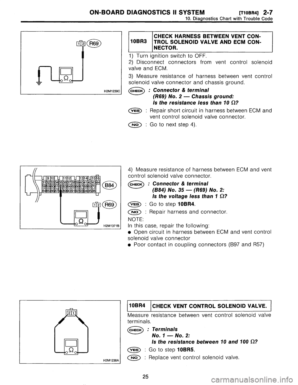
CHECK
HARNESSBETWEEN
VENT
CON-
10BR3
TROL
SOLENOID
VALVE
ANDECM
CON-
NECTOR
.
1)
Turn
ignition
switch
to
OFF
.
2)
Disconnect
connectors
from
vent
control
solenoid
valve
and
ECM
.
3)
Measure
resistance
of
harness
between
vent
control
solenoid
valve
connector
and
chassis
ground
.
CHECK
:
Connector
&
terminal
(R69)
No
.
2
-
Chassis
ground
:
!s
the
resistance
less
than10
S2?
vES
:
Repair
short
circuit
in
harness
between
ECM
and
vent
control
solenoid
valve
connector
.
No
:
Go
to
nextstep
4)
.
(884)
No
.
35
-
(R69)
No
.
2
:
Is
the
voltage
less
than
1
S2?
,rES
:
Go
to
step
10BR4
.
No
;
Repair
harness
and
connector
.
NOTE
:
In
this
case,
repair
the
following
:
*
Open
circuit
in
harness
between
ECM
and
vent
control
solenoid
valve
connector
9
Poor
contact
in
coupling
connectors
(B97
and
R57)
4)
Measure
resistance
of
harness
between
ECM
and
vent
control
solenoid
valve
connector
.
CHECK
:
Connector
&
terminal
10BR4
CHECK
VENT
CONTROL
SOLENOID
VALVE
.
Measure
resistance
between
vent
control
solenoid
valve
terminals
.
CHECK
:
Terminals
No
.
1
-
No
.
2
:
Is
the
resistance
between
10
and
100
S2?
YES
;
Go
tostep
10BR5
.
No
:
Replace
vent
control
solenoid
valve
.
25
Page 237 of 2890
2-7
['r10BR5]
ON-BOARD
DIAGNOSTICS
II
SYSTEM
10
.
Diagnostics
Chart
with
Trouble
Code
R69
E
11U2
D
H2M1241C
I
10BR5
CHECK
I
TROL
SOL
NOID
SUPPLY
VALVE,TO
VENT
CON-
1)
Turn
ignition
switch
to
ON
.
2)
Measure
voltage
between
vent
control
solenoid
valve
and
chassis
ground
.
CHECK
:
Connector
&
terminal
(R69)
No
.
1
(+)
-
Chassis
ground
(
)
:
Is
the
voltage
more
than10
V?
Go
to
next
CHECK
No
:
Repair
harness
and
connector
.
NOTE
:
In
this
case,
repair
the
following
:
e
Open
circuit
in
harness
between
main
relay
and
vent
control
solenoid
valve
"
Poor
contact
in
coupling
connectors
(B97
and
R57)
"
Poor
contact
in
main
relay
connector
CHECK
:
Is
there
poor
contact
in
vent
control
solenoid
valve
connector?
vss
:
Repair
poor
contact
in
vent
control
solenoid
valve
connector
.
No
:
Contact
with
SOA
service
.
NOTE
:
Inspection
by
DTM
is
required,
because
probable
cause
is
deteriorationof
multiple
parts
.
26
Page 242 of 2890
![SUBARU LEGACY 1996 Service Repair Manual
ON-BOARD
DIAGNOSTICS
II
SYSTEM
[TIossz]
2-7
10
.
Diagnostics
Chart
with
Trouble
Code
TNKP
(F43)
0
.
10
k
P
a
1
mmHg
H2M
1326
CHECK
INPUT
SIGNAL
FOR
ECM
.
(USING
10BS2
VOLTAGE
METER
AND
SUBARU
SEL SUBARU LEGACY 1996 Service Repair Manual
ON-BOARD
DIAGNOSTICS
II
SYSTEM
[TIossz]
2-7
10
.
Diagnostics
Chart
with
Trouble
Code
TNKP
(F43)
0
.
10
k
P
a
1
mmHg
H2M
1326
CHECK
INPUT
SIGNAL
FOR
ECM
.
(USING
10BS2
VOLTAGE
METER
AND
SUBARU
SEL](/manual-img/17/57433/w960_57433-241.png)
ON-BOARD
DIAGNOSTICS
II
SYSTEM
[TIossz]
2-7
10
.
Diagnostics
Chart
with
Trouble
Code
TNKP
(F43)
0
.
10
k
P
a
1
mmHg
H2M
1326
CHECK
INPUT
SIGNAL
FOR
ECM
.
(USING
10BS2
VOLTAGE
METER
AND
SUBARU
SELECT
MONITOR
.)
1)
Measure
voltage
between
ECM
connector
and
chassis
ground
.
CHECK
;
Connector
&
terminal
(884)
No
.
21
(+)
-
Chassis
ground
(
)
:
Is
the
voltage
more
than4
.5
V?
YES
:
Go
to
nextstep
2)
.
No
:
Go
to
next
CHECK
CHECK
:
Does
the
voltage
change
more
than
4
.5
Vby
shaking
harness
and
connector
of
ECM
while
monitoring
the
value
with
voltage
meter?
0
:
Repairpoorcontact
in
ECM
connector
.
No
:
Replace
ECM
.
2)
Measure
voltage
between
ECM
and
chassis
ground
.
CHECK
:
Connector
&
terminal
(B84)
No
.
4
(+)
-
Chassis
ground
(
)
:
Is
the
voltage
less
than
0
.2
V?
,mss
:
Go
to
step
10BS3
.
No
:
Go
to
next
step
3)
.
3)
Read
data
onSubaru
Select
Monitor
.
9
Subaru
Select
Monitor
Designate
mode
using
function
key
.
Function
mode
:
F43
9
F43
:
Display
shows
pressure
signal
value
sent
from
fuel
tankpressure
sensor
.
31
Page 243 of 2890
![SUBARU LEGACY 1996 Service Repair Manual 2-7
[T1oBS3]
ON-BOARD
DIAGNOSTICS
II
SYSTEM
10
.
Diagnostics
Chart
with
Trouble
Code
CHECK
:
Does
the
value
change
more
than
-2
.8
kPa
by
shaking
harness
and
connector
of
ECM
while
monitoring
the
SUBARU LEGACY 1996 Service Repair Manual 2-7
[T1oBS3]
ON-BOARD
DIAGNOSTICS
II
SYSTEM
10
.
Diagnostics
Chart
with
Trouble
Code
CHECK
:
Does
the
value
change
more
than
-2
.8
kPa
by
shaking
harness
and
connector
of
ECM
while
monitoring
the](/manual-img/17/57433/w960_57433-242.png)
2-7
[T1oBS3]
ON-BOARD
DIAGNOSTICS
II
SYSTEM
10
.
Diagnostics
Chart
with
Trouble
Code
CHECK
:
Does
the
value
change
more
than
-2
.8
kPa
by
shaking
harness
and
connector
of
ECM
while
monitoring
the
value
with
Subaru
select
monitor?
,rES
:
Repair
poor
contact
in
ECM
connector
.
No
:
Go
to
step
10BS3
.
B2M0927
R47
1z
a
L
E
H2M1255B
I
CHECK
HARNESS
BETWEEN
ECMAND
10BS3
FUEL
TANK
PRESSURE
SENSOR
CONNEC-
TOR
.
1)
Turn
ignition
switch
to
OFF
.
2)
Detach
right
siderear
quarter
trim
panel
.
3)
Remove
right
siderear
quarter
trim
pocket
.
4)
Detach
right
siderear
quarter
insulator
.
5)
Disconnect
connector
from
fuel
tank
pressure
sensor
.
6)
Turn
ignition
switch
to
ON
.
7)
Measure
voltage
between
fuel
tank
pressure
sensor
connector
and
chassis
ground
.
CHECK
;
Connector
&
terminal
(R47)
No
.
3
(+)
-
Chassis
ground
(
)
:
Is
thevoltage
more
than
4
.5
V?
vES
:
Go
to
nextstep
8)
.
*
Open
circuit
in
harness
between
ECM
and
fuel
tank
pressure
sensor
connector
e
Poor
contact
in
coupling
connector
(B97)
No
:
Repair
harness
and
connector
.
NOTE
:
In
this
case,
repair
the
following
:
32
Page 245 of 2890
2-7
IT10BS4]
ON-BOARD
DIAGNOSTICS
II
SYSTEM
10
.
Diagnostics
Chart
with
Trouble
Code
H2M1257B
I
82M0927
11)
Measure
resistance
of
harness
between
fuel
tank
pressure
sensor
connector
and
chassis
ground
.
CHECK
:
Connector
&
terminal
the
kW
CHECK
:
Is
there
poor
contact
in
fuel
tank
pressure
sensor
connector?
vES
:
Repair
poor
contact
in
fuel
tank
pressure
sensor
connector
.
Replace
fuel
tank
pressure
sensor
.
No
:
(R47)
No
.
1
-
Chassis
ground
:
Is
resistance
more
than
500
Go
to
next
CHECK
No
:
Repair
short
circuit
in
harness
between
ECM
and
fuel
tank
pressure
sensor
connector
.
CHECK
HARNESS
BETWEEN
ECM
AND
10BS4
FUEL
TANK
PRESSURE
SENSOR
CONNEC-
TOR
.
1)
Turn
ignition
switch
to
OFF
and
Subaru
Select
Moni-
tor
or
the
OBD-II
general
scan
tool
switch
to
OFF
.
2)
Detach
right
siderear
quarter
trim
panel
.
3)
Remove
right
siderear
quarter
trim
pocket
.
4)
Detach
right
siderear
quarter
insulator
.
34