1996 LAND ROVER DEFENDER oil
[x] Cancel search: oilPage 82 of 455

ENGINE
23
REPAIR
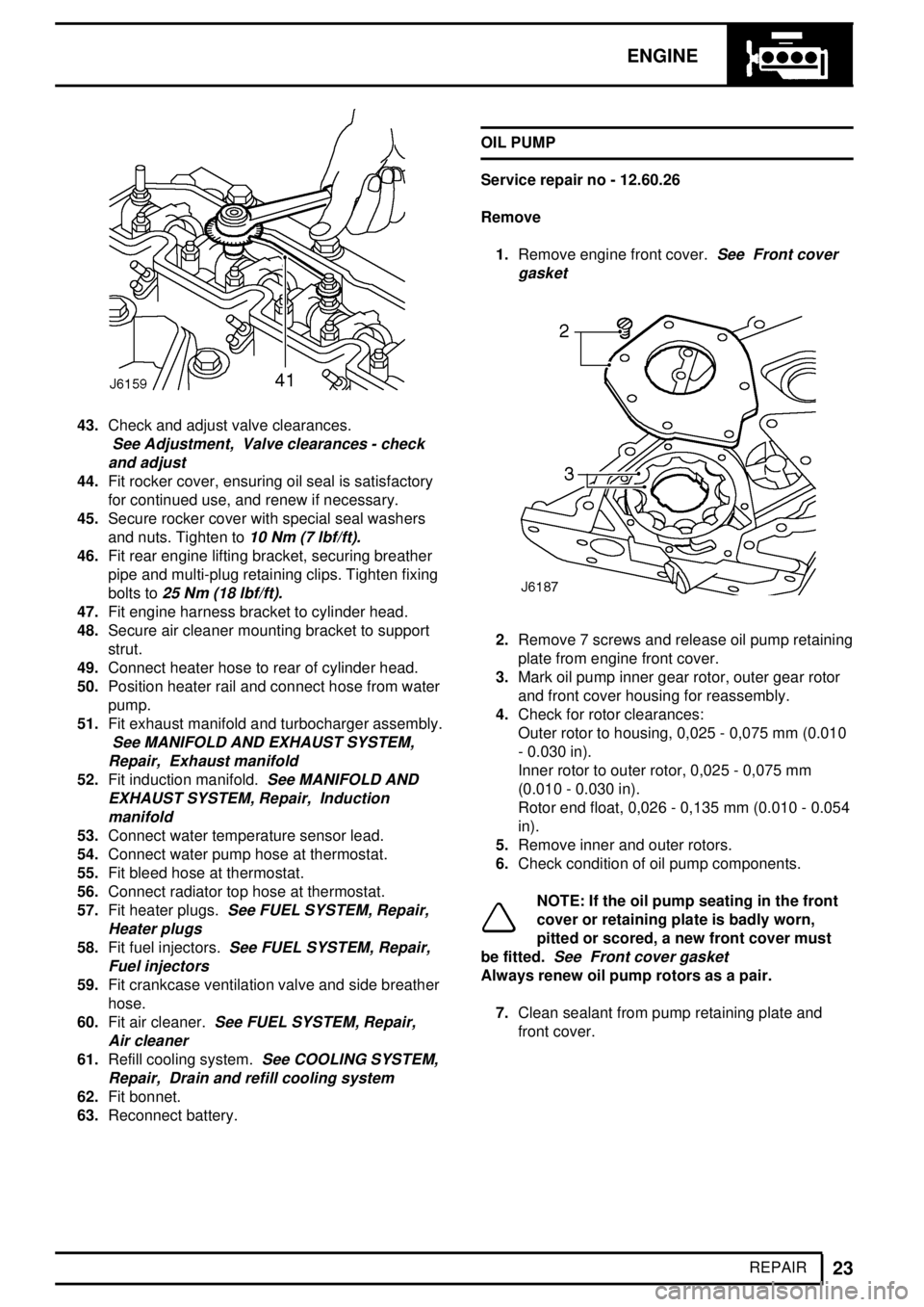
43.Check and adjust valve clearances.
See Adjustment, Valve clearances - check
and adjust
44.Fit rocker cover, ensuring oil seal is satisfactory
for continued use, and renew if necessary.
45.Secure rocker cover with special seal washers
and nuts. Tighten to
10 Nm (7 lbf/ft).
46.Fit rear engine lifting bracket, securing breather
pipe and multi-plug retaining clips. Tighten fixing
bolts to
25 Nm (18 lbf/ft).
47.Fit engine harness bracket to cylinder head.
48.Secure air cleaner mounting bracket to support
strut.
49.Connect heater hose to rear of cylinder head.
50.Position heater rail and connect hose from water
pump.
51.Fit exhaust manifold and turbocharger assembly.
See MANIFOLD AND EXHAUST SYSTEM,
Repair, Exhaust manifold
52.Fit induction manifold.See MANIFOLD AND
EXHAUST SYSTEM, Repair, Induction
manifold
53.Connect water temperature sensor lead.
54.Connect water pump hose at thermostat.
55.Fit bleed hose at thermostat.
56.Connect radiator top hose at thermostat.
57.Fit heater plugs.
See FUEL SYSTEM, Repair,
Heater plugs
58.Fit fuel injectors.See FUEL SYSTEM, Repair,
Fuel injectors
59.Fit crankcase ventilation valve and side breather
hose.
60.Fit air cleaner.
See FUEL SYSTEM, Repair,
Air cleaner
61.Refill cooling system.See COOLING SYSTEM,
Repair, Drain and refill cooling system
62.Fit bonnet.
63.Reconnect battery.OIL PUMP
Service repair no - 12.60.26
Remove
1.Remove engine front cover.
See Front cover
gasket
2.Remove 7 screws and release oil pump retaining
plate from engine front cover.
3.Mark oil pump inner gear rotor, outer gear rotor
and front cover housing for reassembly.
4.Check for rotor clearances:
Outer rotor to housing, 0,025 - 0,075 mm (0.010
- 0.030 in).
Inner rotor to outer rotor, 0,025 - 0,075 mm
(0.010 - 0.030 in).
Rotor end float, 0,026 - 0,135 mm (0.010 - 0.054
in).
5.Remove inner and outer rotors.
6.Check condition of oil pump components.
NOTE: If the oil pump seating in the front
cover or retaining plate is badly worn,
pitted or scored, a new front cover must
be fitted.
See Front cover gasket
Always renew oil pump rotors as a pair.
7.Clean sealant from pump retaining plate and
front cover.
Page 83 of 455

12ENGINE
24
REPAIR Refit
8.Fit oil pump rotors in front cover.
9.Apply a bead of RTV sealant around retaining
plate.
10.Fit oil pump retaining plate to front cover,
securely tighten screws.
11.Fit front cover to cylinder block.
See Front
cover gasket
OIL PRESSURE RELIEF VALVE
Service repair no - 12.60.56
Remove
1.Remove engine oil sump.
See Engine oil
sump
2.Unscrew relief valve retaining plug from base of
front cover.
3.Withdraw valve spring and plunger and check for
wear.
Valve spring free length, 68.00 mm (2.68 in).
NOTE: If the valve plunger sleeve is badly
worn, pitted or scored, a new front cover
must be fitted.
See Front cover gasket
Always renew valve spring and plunger as a pair.
Refit
4.Insert valve plunger and spring into sleeve in
front cover and secure with retaining plug.
5.Fit engine oil sump.
See Engine oil sump
Page 84 of 455

ENGINE
1
SPECIFICATIONS, TORQUE REV: 05/99 TORQUE VALUES
NOTE: Torque wrenches should be regularly checked for accuracy to ensure that all fixings are
tightened to the correct torque.
Nm
Engine block
Bearing cap 133...............................................................................................
Blanking plug, oil gallery, rear 37....................................................................
Oil squirt jet assembly 17................................................................................
Drain plug, cylinder block 25...........................................................................
Oil squirt jet, vacuum pump cam 7.................................................................
Connecting rod to cap 59................................................................................
Oil pick up assembly to bearing cap 9...........................................................
Oil pick up assembly to front cover 25............................................................
Camshaft thrust plate 9..................................................................................
Oil drain pipe to block (internal) 25.................................................................
Oil drain pipe to block (external) 25................................................................
Sump to cylinder block and front cover 25......................................................
Drain plug, oil sump 35...................................................................................
Tappet guide 14..............................................................................................
Breather side cover assembly 25....................................................................
Baffle plate to breather side cover 4..............................................................
Vacuum pump 25............................................................................................
Fuel lift pump 25.............................................................................................
Flywheel housing 45.......................................................................................
Flywheel housing clutch cover stud 10...........................................................
Plug, flywheel housing 12...............................................................................
Rear oil seal assembly 25...............................................................................
Oil filter adaptor 45..........................................................................................
Waxstat adaptor to oil filter adaptor 9............................................................
Oil pressure switch 17.....................................................................................
Oil filter, spin on 13.........................................................................................
Oil cooler unions to filter adaptor 45...............................................................
Oil level tube 25..............................................................................................
Engine mounting foot to cylinder block 85......................................................
Engine mounting foot to flywheel housing 45.................................................
Engine mounting foot rubber to mounting foot (bolt and nut) 85.....................
Flywheel to crankshaft 146..............................................................................
Clutch cover plate to flywheel 34....................................................................
Flex drive plate to crankshaft (auto) 146..........................................................
Flex drive plate to ring gear (auto) 25.............................................................
Flex drive plate to torque converter (auto) 45.................................................
Page 86 of 455

ENGINE
3
SPECIFICATIONS, TORQUENm
Turbo charger oil drain adaptor to block 42....................................................
Oil drain pipe to turbocharger 25....................................................................
Turbocharger oil drain pipe to adaptor 38.......................................................
Turbocharger oil feed pipe adaptor to block 25...............................................
Turbocharger oil feed pipe to adaptor 25........................................................
Oil feed pipe to turbocharger 19.....................................................................
Turbocharger to cylinder head (stud) 10.........................................................
Turbocharger to cylinder head (nut) 45...........................................................
Turbocharger to blanking plate 25..................................................................
Turbocharger to EGR valve 25.......................................................................
EGR delivery tube to valve 25........................................................................
EGR delivery tube to mixing tube 25..............................................................
Fuel lift pump to filter (union) 15.....................................................................
Fuel filter from lift pump (banjo bolt) 33...........................................................
Fuel filter to fuel injection pump (banjo bolt) 33..............................................
Fuel injection pump from fuel filter (banjo bolt) 25..........................................
Injector pipes to injectors and fuel injection pump 29.....................................
Spill rail to injectors (banjo bolt) 10.................................................................
Spill rail to injection pump (banjo bolt) 25.......................................................
Boost pipe injection pump (banjo bolt) 10.......................................................
Plug, rear of injection pump 29.......................................................................
PAS pump to mounting plate 25.....................................................................
PAS pump mounting plate to auxiliaries mounting bracket 25........................
PAS pump pulley to hub 25............................................................................
Starter motor (bolt and nut) 45........................................................................
Air conditioning compressor
Compressor mounting bracket to front cover 45.............................................
Compressor to mounting bracket (stud) 8......................................................
Compressor to mounting bracket (nut) 25......................................................
Belt tensioner pulley to tensioner arm 45........................................................
Belt tensioner assembly to front cover plate 25..............................................
Idler pulley to front cover plate 45...................................................................
Compressor belt guard (nut) 25......................................................................
Sensors to water outlet elbow (air/con) 25......................................................
Blanking plug, water outlet elbow (air/con) 25................................................
Generator
Generator mounting bracket to front cover 45................................................
Generator to mounting bracket 85..................................................................
Generator pulley to hub 95.............................................................................
Generator belt guard 25..................................................................................
Generator to auxiliaries mounting bracket 25.................................................
Tachometer electrical connection 4...............................................................
Page 100 of 455

FUEL SYSTEM
3
ADJUSTMENT INJECTION PUMP TIMING - CHECK AND ADJUST
Service repair no - 19.30.01
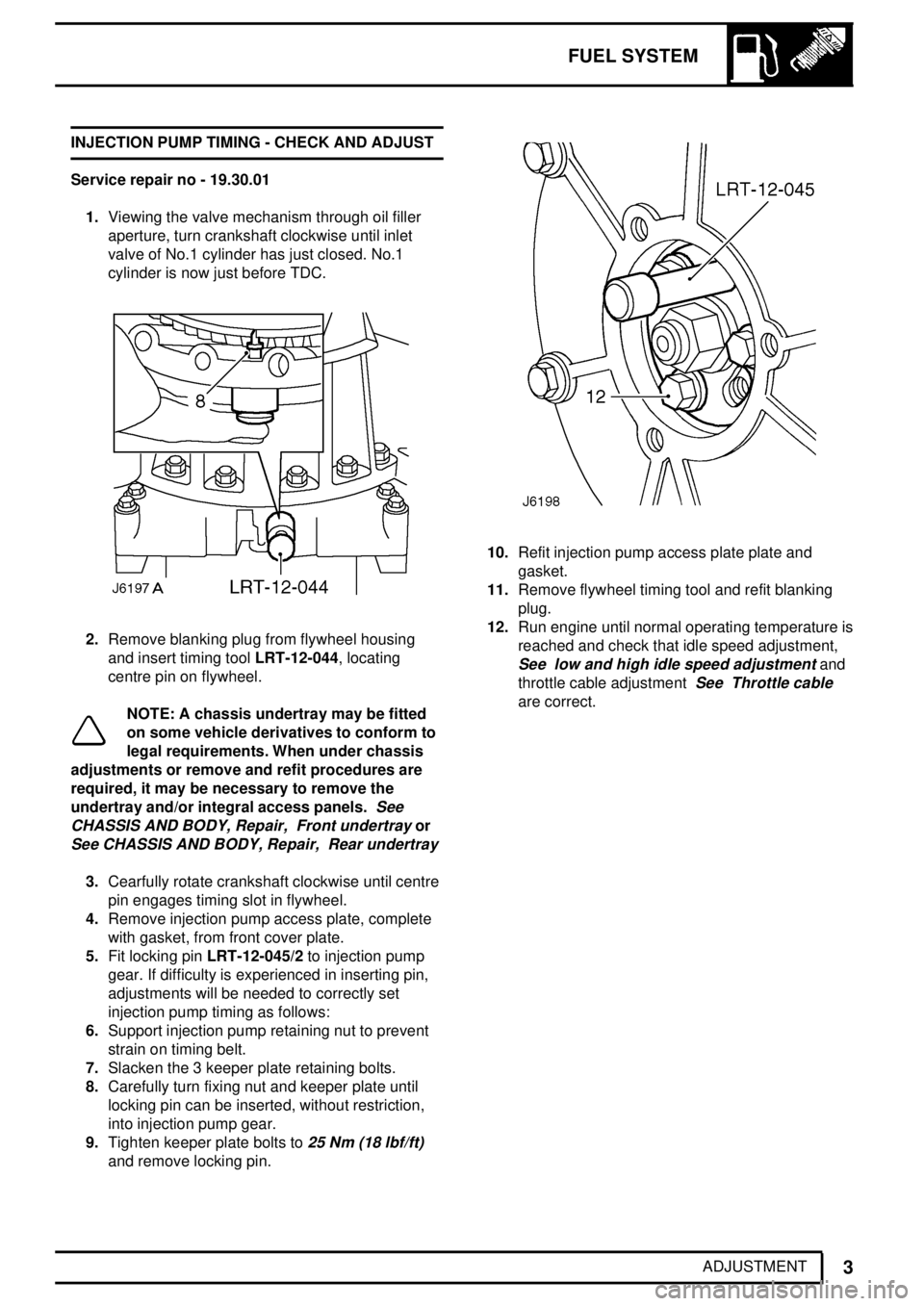
1.Viewing the valve mechanism through oil filler
aperture, turn crankshaft clockwise until inlet
valve of No.1 cylinder has just closed. No.1
cylinder is now just before TDC.
2.Remove blanking plug from flywheel housing
and insert timing toolLRT-12-044, locating
centre pin on flywheel.
NOTE: A chassis undertray may be fitted
on some vehicle derivatives to conform to
legal requirements. When under chassis
adjustments or remove and refit procedures are
required, it may be necessary to remove the
undertray and/or integral access panels.
See
CHASSIS AND BODY, Repair, Front undertray
or
See CHASSIS AND BODY, Repair, Rear undertray
3.Cearfully rotate crankshaft clockwise until centre
pin engages timing slot in flywheel.
4.Remove injection pump access plate, complete
with gasket, from front cover plate.
5.Fit locking pinLRT-12-045/2to injection pump
gear. If difficulty is experienced in inserting pin,
adjustments will be needed to correctly set
injection pump timing as follows:
6.Support injection pump retaining nut to prevent
strain on timing belt.
7.Slacken the 3 keeper plate retaining bolts.
8.Carefully turn fixing nut and keeper plate until
locking pin can be inserted, without restriction,
into injection pump gear.
9.Tighten keeper plate bolts to
25 Nm (18 lbf/ft)
and remove locking pin.
10.Refit injection pump access plate plate and
gasket.
11.Remove flywheel timing tool and refit blanking
plug.
12.Run engine until normal operating temperature is
reached and check that idle speed adjustment,
See low and high idle speed adjustmentand
throttle cable adjustment
See Throttle cable
are correct.
Page 103 of 455

FUEL SYSTEM
1
REPAIR FUEL INJECTION PUMP
Service repair no - 19.30.07
Remove
1.Disconnect battery.
2.Disconnect and remove high pressure fuel
injection pipes, pump to injectors.
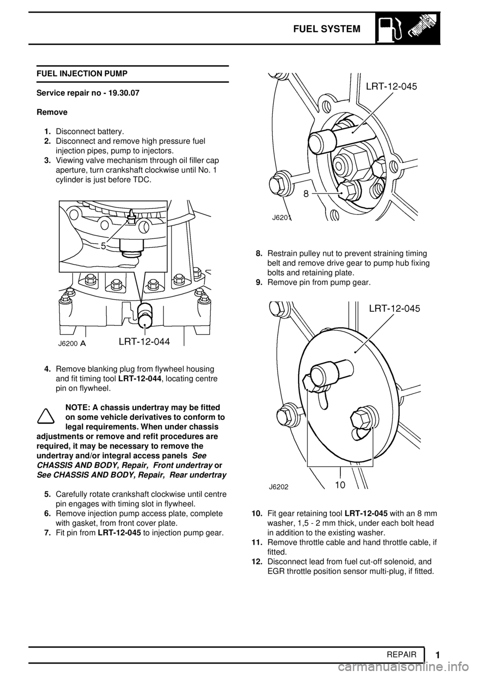
3.Viewing valve mechanism through oil filler cap
aperture, turn crankshaft clockwise until No. 1
cylinder is just before TDC.
4.Remove blanking plug from flywheel housing
and fit timing toolLRT-12-044, locating centre
pin on flywheel.
NOTE: A chassis undertray may be fitted
on some vehicle derivatives to conform to
legal requirements. When under chassis
adjustments or remove and refit procedures are
required, it may be necessary to remove the
undertray and/or integral access panels
See
CHASSIS AND BODY, Repair, Front undertray
or
See CHASSIS AND BODY, Repair, Rear undertray
5.Carefully rotate crankshaft clockwise until centre
pin engages with timing slot in flywheel.
6.Remove injection pump access plate, complete
with gasket, from front cover plate.
7.Fit pin fromLRT-12-045to injection pump gear.
8.Restrain pulley nut to prevent straining timing
belt and remove drive gear to pump hub fixing
bolts and retaining plate.
9.Remove pin from pump gear.
10.Fit gear retaining toolLRT-12-045with an 8 mm
washer, 1,5 - 2 mm thick, under each bolt head
in addition to the existing washer.
11.Remove throttle cable and hand throttle cable, if
fitted.
12.Disconnect lead from fuel cut-off solenoid, and
EGR throttle position sensor multi-plug, if fitted.
Page 105 of 455

FUEL SYSTEM
3
REPAIR FUEL INJECTORS
Service repair no - 19.60.10
Remove
NOTE: When a fuel injector is considered
to be the cause of irregular running and
loss of power it will be necessary to fit a
donor set of injectors to determine which injector
is at fault. DO NOT attempt to dismantle or carry
out spray tests on the fuel injectors. This work
can only carried out by authorised Bosch dealers.
1.Remove oil filler cap and release sound
insulation cover from top of engine.
2.Disconnect high pressure fuel supply pipes from
injectors and injection pump. Remove in pairs.
3.Disconnect spill return hose(s) from injectors.
4.Plug pipes and injector connections to prevent
the ingress of dirt and foriegn matter.5.Remove retaining nut and release each injector
clamp plate from cylinder head.
6.Remove injector and discard copper washer.
Refit
7.Ensure injectors and seating in cylinder head are
clean.
8.Lightly grease a new copper sealing washer and
position on each injector.
9.Fit injectors in cylinder head with spill return
outlets facing outward.
10.Secure injector with clamp plate and nut. Tighten
nut to
25 Nm (18 lbf/ft).
NOTE: The clamp plates are slightly
curved and should be fitted with the
convex side uppermost.
11.Fit the spill return pipe with a single copper
washer under the head of the banjo bolt and 2
copper washers fitted between the injector and
the banjo. Tighten banjo bolt to
10 Nm (7 lbf/ft).
12.Fit high pressure pipes to injectors and injection
pump. Tighten union nuts to
28 Nm (21 lbf/ft).
13.Fit sound insulation cover and oil filler cap.
Page 113 of 455

FUEL SYSTEM
11
REPAIR HEATER PLUGS
Service repair no - 19.60.31
Remove
1.Disconnect battery.
No.1 heater plug - air conditioning models:
2.Release drive belt from compressor pulley.See
AIR CONDITIONING, Repair, Compressor
drive belt
3.Remove 4 bolts securing compressor to front
cover, move compressor aside.
No.3 heater plug:
4.Remove retaining bolt and withdraw breather
valve from rocker cover. Remove and discard 'O'
ring.
All heater plugs:
5.Remove terminal nut and disconnect wire from
heater plug terminal.
6.Unscrew heater plug.
Refit
7.Clean heater plug and seating.
8.Coat threads of heater plug with suitable
anti-seize compound operational to a
temperature of 1000°C.
9.Fit heater plug, tighten to
23 Nm (17 lbf/ft).
10.Connect wire to heater plug terminal and secure
with nut.
NOTE: Feed wire must be connected to
No. 4 heater plug terminal.
No. 3 heater plug:
11.Lubricate new 'O' ring with engine oil and fit to
breather valve.
12.Fit valve to rocker cover, tighten to bolt to
15 Nm
(11 lbf/ft).
No. 1 heater plug - air conditioning models
13.Position compressor to front cover, fit bolts and
tighten to
25 Nm (18 lbf/ft).
14.Fit drive belt to compressor pulley and adjust
tension.
See AIR CONDITIONING, Repair,
Compressor drive belt
All models:
15.Reconnect battery.