Page 757 of 2189
Troubleshooting Flowchart - Brake Switch Signal
Symptom
Shift lever cannol b€ moved f.om
B pGition with the brako podrl
depr8sed.
PCM CONNECTORS
Check Brako Light Operation:Deoress the brake pedal.
Rop.ir faulty braks switch cilcuit
lsos soction 231.Are the brake lights ON?
Measure SToP SW Vohag€:1. Turn the ignition switch OFF.2. Disconnect the A l32P) and D
{l6P) connectors from thoPCM.3. Measure the voltage belweenthe D5 and A9 or A22 termi-nals with the brake Pedaldepressod.
Rap.i. opon in the wira bctn oentha 05 terminal and tho btrkclwitdr.ls there battery voltage?
. Brake switch 3ign.l is OK.. Ch6ck lor looao PCM oonnoctors.It nocassary, aubctilute a known-good PCM and r€check.. Inspoct the brake switch circuit
{s6e section 231.
Wire side of lemale terminals
Page 779 of 2189

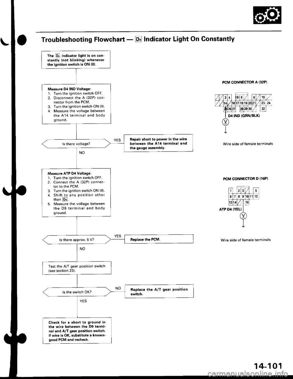
Troubleshooting Flowchart - El Indicator Light On Constantly
PCM CONNECTOR A I32P)
Wire side of lemale terrnanals
PCM CONNECTOR D {16P)
ATP D'
25
61e 11(12
t{Iro
(YELI
Wire side of female terminals
The Dll indicator lighi is on con-stantly {not blinking) whenever
the ignition switch is ON (lll.
Moasure D4 IND Voltage:1. Turn the ignition switch OFF.2. Disconnect the A {32P} con-nector from the PCM.3. Turn the ignition switch ON (ll).
4. Measure the voltage betweenthe A14 terminal and bodyground.
Repsir short to power in the wire
between the A14 torminal andthe gauge assembly.
Measure ATP D4 Voltagel1. Turn the ignition switch OFF.2. Connect the A (32P) connector to the PCM.3. Turn the ignition switch ON (ll).
4. Shitt to any position othertha n [ql.5. Measure the voltage betweenthe D9 terminal and bodyground.
ls there approx. 5 V?
Test the A/T gear position switch(see section 23).
Check Ior a short to ground inthe wire betweon the D9 termi-
nal and A/T gear position switch.It wire is OK, substitute a known-good PCM and recheck.
Page 782 of 2189
ElectricalTroubleshooting ('99 - 00 Modelsl
Troubleshooting Flowchart - Brake Switch Signal
PCM CONNECTORS
Wire side of female terminals
Shift lever cannot be moved tromE position with tho b.ake pedaldepressod.
Check Brake Light Operation:Depress the brake pedal.
Repair t ulty brake switch circuit{see s€ction 23}.Are the brake llghts ON?
Mea3ure STOP SW Vohage:1. Turn the ignition switch OFF.2. Disconnect the A (32P) and B{25P} connectors from thePCM,3. Measure the voltage betweenthe A32 and 820 or 822 termi-nals with the brake pedal
depressed.
Repair open in the wire betwsenthe A32 terminal rnd tho brrk6switch.
ls there battery voltage?
. Brak€ switch sign.l is OK.. Check for loose terminal fil inlhe PCM conn€ctors. lf neces-sary. substitute a known-goodPICM and recheck.. InsDect the breke 3witch circuitlsee section 231.
B {25P)
\
14-104
Page 791 of 2189

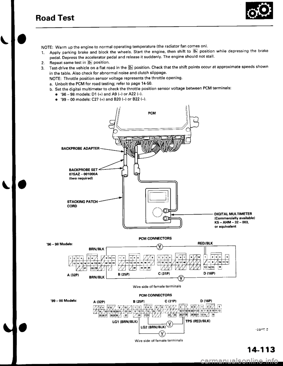
Road Test
NOTE: Warm up the engine to normal operating tem peratu re (the rad iator fan comes on )'
1. Apply parking brake and block the wheels. Start the engine, then shift to E position while depressing the brake
Dedal, Depress the accelerator pedal and release it suddenly. The engine should not stall'
2. Repeat same test in E Position.
3. Test-drive the vehicle on a flat road in the E position. Check that the shift points occur at approximate speeds shown
in the table. Also check for abnormal noise and clutch slippage.
NOTE: Throttle position sensor voltage represents the throttle opening
a. Unbolt the PCM for road testing; refer to page 14-50.
b. Setthedigital multimeter to check the th rottle position sensor voltage between PCM terminals;
. '96 - 98 models: D1 {+) and A9 (-) or 422 (-}.
. '99 - 00 models: C27 (+) andB20t-) orB22{-}.
BACKPROBE ADAPTER
BACKPROBE SET07sAz - 001oq)A{two requiredl
DIGIIAL MULTIMETERlCommercially available)KS-AHM-32-003,or equivalenl
'96 - 98 Modelsr
Wire side ol temale terminals
PCM CONNECTORS
B t25Pl c (31P)
LG1 IBRN/BLK)
I (25P1c (31P}
A t32PtD (16P)
Wire side ol female terminals
'9!t - 00 Models:
1+113
Page 943 of 2189

Electrical Troubleshooting ('99 - 00 Models)
Troubf eshooting Flowcharl - AIT Gear Position Switch {Short) {cont,d}
From page 14 265
LGl IBRN/BLK) LG2 {BRN/BLK}
Wire side of female terminals
A t32Pl jl B {25P)
ATP D (YEL)
LG1 {BRN/ALKILG2 IBRN/BLK)
Measure ATP NP Voltage:'1. Shift to all positions other thanEorI2. Measure the voltage betweenthe A9 and 820 or 922 te(mi-nals.
Check for short in the wirebetwoen ths Ag terminal and theA/T gerr position switch, .nd inthe E .nd E position 3ignalwiros botween the A/T gearposition indic.tor and the A/Tgear positaon switch. lf wircs .reOK, check tor loose terminal tit inthe PCM connectols. lf n€ces-3ary, substitute a known-goodPCM and rocheck.
ls there approx. 10 V?
Me.sure ATP D Vohago:1. Shift to all positions otherthan E.2. Measure the voltage betweenthe 47 and 820 ot 822 tet-r'i-nals,
Check tor 3hort in lhe wireb€twaen thc A7 terminel and theA/T g6ar position switch. lf wir.sare OK, ch.rck to. loose terminalfit in th6 PCM connectoF. lf nsc-ossary. substhute a known-goodPCM and ..check.
ls there approx. 10 V?
a l32Pl ll B (25P1
To page 14-267
14-266
Page 944 of 2189

M6asure ATP S Voliag€:1. Shift to all positions other
than E.2. Measure the voltage between
the D13 and 820 or 822 termi
nals.
Check for short in the wire
between the D13 terminal and
the A/T gear position lwitch orA/T goar position indicator. Itwir6s are OK, check lor loose l€r-
minal fit in the PCM connectors.ll nec*3arv, substitute a known'good PCM and r6check.
ls there approx. '10 V?
Measure ATP L Voltage:1. Shi{t to all positions other
than E.2. Measure the voltage between
the A22 and 820 or 822 termi-nals.
Check lor sho.t in ihe wire
betwgon the A22 terminal and
th. A/T geat position switch or
A/T gear position indicator. It
wires are OK, ch€ck for 10036 ter-minal fit in the PCM connectors.lf n6cessery, substitute a known_good PCM and recheck.
ls there approx- 10 V?
Check tor loos€ terminalfit in the
PCM connectors, It nec6s3arY,
substitute a known-good PCM
and rech6ck.
From page 14-266
B t2sP)
LG1{BRN/BLKI
t32Pl
PCM CONNECTORS
Wire side of Iemale terminals
PCM CONNECTORS
D (16P1
ATP S {LT GRN/RED)
LG2 (BRN/BLKI
B t25Pl
Page 946 of 2189
From page 14-268
LGl IBRN/BLK}
Moasule ATP D voltago:1. Shift to El position.
2. Measure the voltage between
the A7 and 820 or 822 termi
nals.
Repair open in the wira betwo6nthe A7 torminal and the A/T ge.rpo3ition switch.
Measure ATP S Vollag6:'1. Shiftto E position.
2. Measure the voltage betweenthe D13 and 820 or B22 terminals.
Repair op€n in tho wire betweenihe D13 terminal .nd the A/Tgear position switch,
A {32P} ll B l25Pl
LGl IBRN/BLK) LG2 (BRN/BLKI
(cont'd)
14-269
To page 14-270
Page 967 of 2189

ElectricalTroubleshooting ('gg - 00 Models)
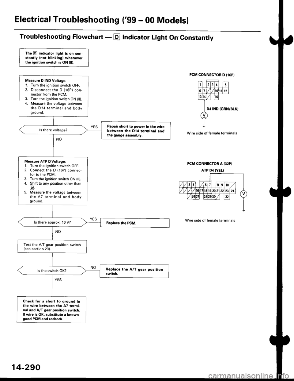
Troubleshooting Flowchart - E Indicator Light On Constantly
FCM CONNCCTOR D tl6PI
23I5
61t012
tsll / rc
II D4 rND
o
(GRN/BLK)
Wire side of female terminals
rcM CONNECTOR A I32PI
ATP Dil {YELI
Wire side of lemale terminals
The E indicator light is on con-stantly {not blinkingl wheneverthe ignition switch is ON lll|.
Mersure D IND Voltage:1. Turn the ignition switch OFF.2. Disconnect the D (16P) con-nector from the PCM.3. Turn the ignition switch ON (ll).4. Measure the voltage betweenthe 014 terminal and bodyground,
Repair short to power in tho wirebstween the Dl4 termin.l sndthe gaug€ r3sembly.
Measure ATP DVoltage:1. Turn the ignition switch OFF.2. Connect the D (16Pi connec-tor to the PCM.3. Turn the ignition switch ON lll).4. Shift to any position other thanE,5. lMeasure the voltage betweenthe 47 terminal and bodyground.
ls there approx. 10 V?
Test the A/T gear position switch{see section 23).
Check for a shorl lo ground inthe wire between tho A7 termi-nal and A/T ge.r polition switch.l, wire is OK, substitute a known-good PCM and recheck.
14-290