Page 724 of 2189

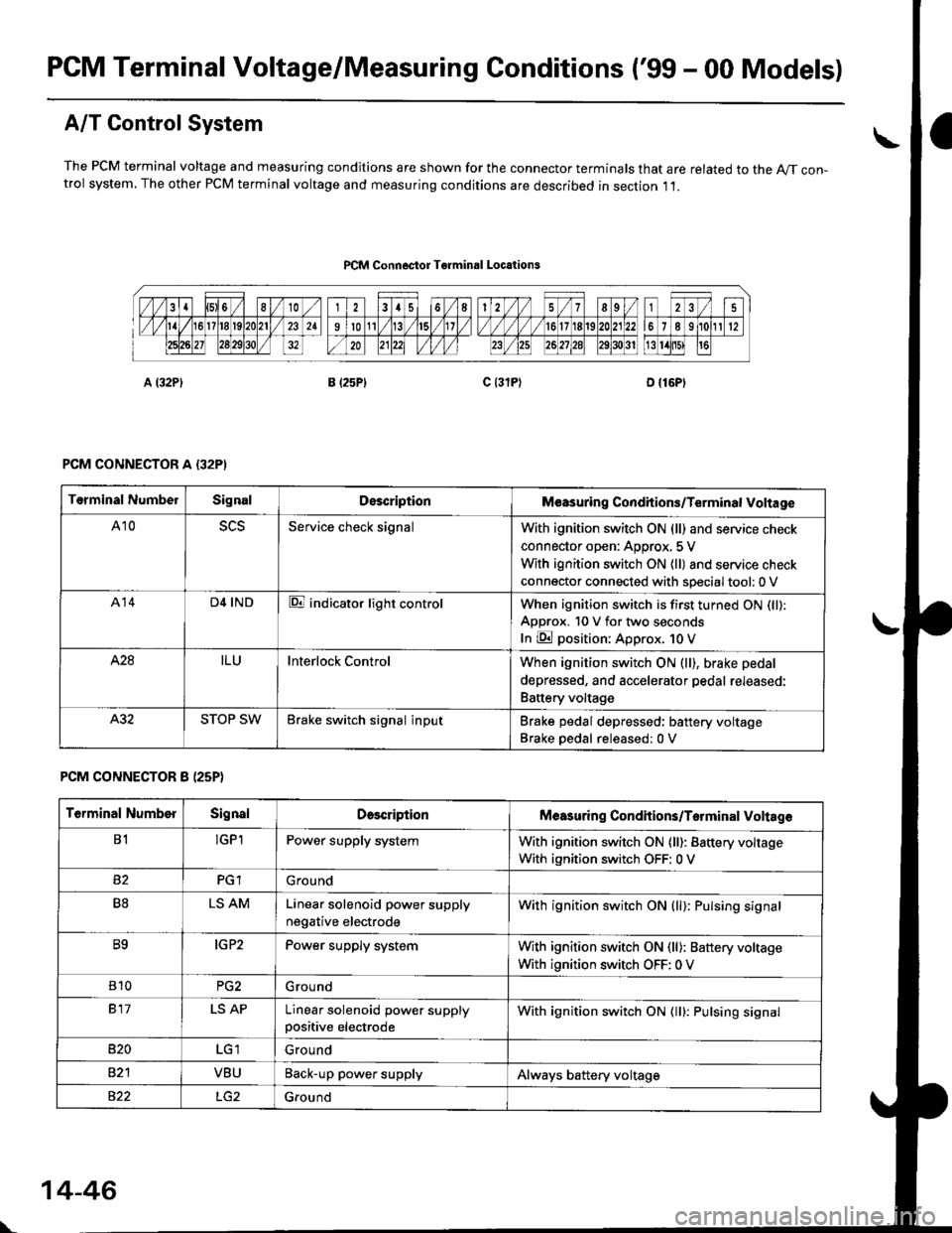
PCM Terminal Voltage/Measuring Conditions ('99 - 00 Models)
A/T Control System
The PCM terminal voltage and measuring condjtions are shown for the connector terminals that are related to the A//T con-trol system, The other PCM terminal voltage and measuring conditions are described in section ,11.
PCM Connoctor Tgrminrl Locations
PCM CONNECTOR A {32PI
PCM CONNECTOR 8 (25P}
Terminal NumbelSignalDescriptionM€asuring Conditions/Terminal Voltage
A105L5Service check signalWith ignition switch ON (ll) and service check
connector open: Approx, 5 V
With ignition switch ON (ll) and service check
connector connected with sDecial tool: 0 V
A14D4 INDE indicator light controlWhen ignition switch is first turned ON (ll):
ApDrox. 10 V for two seconds
In E position: Approx. 1O V
428ILUInterlock ControlWhen ignition switch ON (ll), brake pedal
depressed, and accelerator pedal rereaseo:
Battery voltage
A.32STOP SWBrake switch signal inputBrake pedal depressed: battery voltage
Brake oedal released:0 V
Terminal NumberSignalDescdptionMeasuring Condhions/Torminal Voltag6
B1!GP1Power supply systemWith ignition switch ON (ll): Battery voltage
With ignition switch OFF: 0 V
PGlGround
B8LS AMLinear solenoid power supply
negative electrode
With ignition switch ON (ll): Pulsing signal
B9IG P2Power supply systemWith ignition switch ON (ll): Baftery voltage
With ignition switch OFF: 0 V
810PG2G rou nd
917LS APLinear solenoid power supplypositive electrode
With ignition switch ON (ll): Pulsing signal
B�20Ground
VBUBack-up power supplyAlways battery voltage
822Ground
\
14-46
Page 734 of 2189

Electrical Troubleshooting (,96 - gg Models)
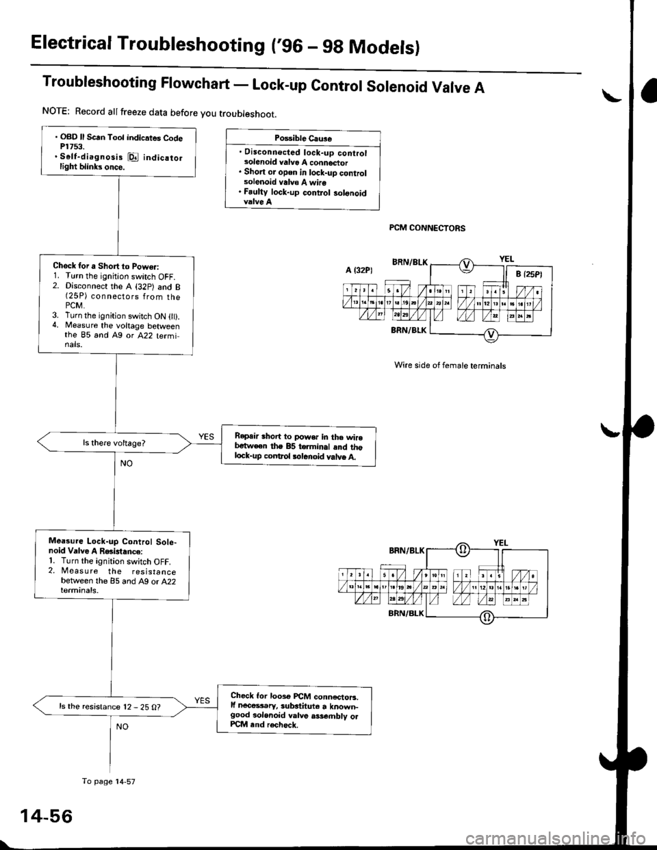
Troubleshooting Flowchart - Lock-up contror sorenoid Varve A
Po$ible Cau3e
. Disconnecled lock-up controlsolenoid valvo A connector. Short or open in lock-uD controlsolenoid valv€ A wire. Fauliy lock-up contlol solonoidvalve A
PCM CONNECTORS
Wire side of female terminals
. OBD ll Scrn Toot indicates CodeP1753.. Self-diagnosis @ indicatorlight blinks once.
Check for a Short to Powo.:1. Turn the ignition switch OFF.2. Disconnect the A (32p) and B(25P) connsgl6ps 1rq- thaPCM.3. Turn the ignition swjtch ON 0t).4, Measure the voltage betweenthe 85 and Ag or A22 terminals.
Repair shoit to power in the wirebetw€en the 85 terminal and thglock-up coDtrol tolenoid valve A.
Mea3ure Lock-up Control Sole-noid Valve A RGislance:'1. Turn the ignition switch OFF.2. Measure the resistancebetween the 85 and A9 or A22terminals.
Check lor looso PCM conn€ctoB.lf nece$.ry, substituto a known-good aolonoid valve ass€.nblv olPCM end rech6ck.
ls the resistance 12 - 25 O?
NOTE: Record allfreeze data before you troubleshoot.
A l32P)
To page'14-57
Page 736 of 2189

Electrical Troubleshooting ('96 - 9g Modelsl
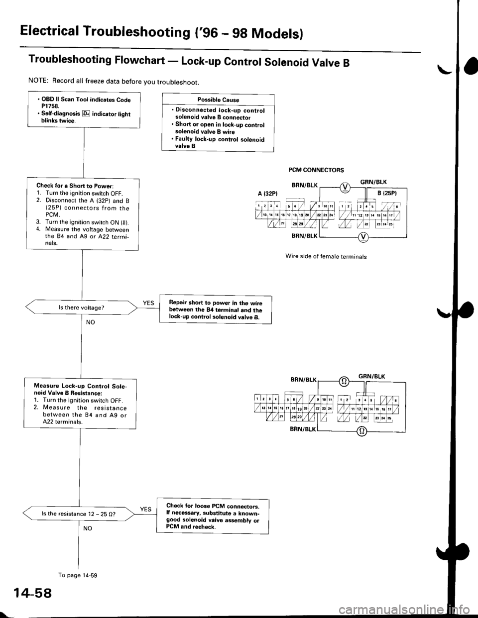
Troubleshooting Ftowchart - Lock-up control sorenoid Varve B
Possible Cause
. Disconnected lock-up controlsolenoid valve B connector' Short or open in lock-up controlsolonoid valve B whe. Faulty lock-up control solenoidvalve B
PCM CONNECTORS
Wire side of female terminals
. OBD ll Scan Tool indicrtes CodeP1758.. Self-diagnosis E indicrtor lightblinkstwice.
Check for a Shon to Power:1. Turn the ignition switch OFF.2. Disconnect the A (32p) and B(25P) connectors from thePCM,3. Turn the ignition switch ON t).4. Measure the voltage betweenthe 84 and A9 or A22 termi-nals.
Repeir short to power in the wirebetween the 84 teiminal and thelock-up control solenoid valve B.
Moasure Lock-up Control Sole-noid Valve B Resistance:1. Turn the ignition switch OFF.2. Measure the resistancebetween the 84 and Ag orA22 terminals.
Check for loose FCM connectors,lf necessary, substitute a known-good solenoid valve assembly olP1CM and rech6ck.
ls the resistance 12 - 25 O?
NOTE: Record all freeze data before you troubleshoot.
A {32P)
To page 14-59
t-
Page 742 of 2189

Electrical Troubleshooting ('96 - 98 Modelsl
Troubleshooting Flowchart - Shift Gontrol Solenoid Valve A
Po$ible Cau3e
. Disconnected shift controlsolenoid valve A connector. Short oi open in shift controlsolenoid valve A wire. Faulty shirt control solenoid
PCM CONNECTORS
' OBD ll Scan Tool indicates CodeP0753.. Sett{iagnosis E indicator lightblinks seven tim6.
Check tor a Short to Power:1. Turn the ignition switch OFF.2. Disconnect the A (32P) and B{25 Pi connectors trom thePCM.3. Turn the ignition switch ON {ll).4. Measure the voltage betweenthe 83 and A9 orA22 terminals.
Repair short to powe. in the wir6between the 83 terminal .nd theshift control solonoid valvo A.
Moa3ure Shift Control SolenoidValve A Resistanc€:1. Turn the ignition switch OFF.2, Measure the resistancebetween the 83 and A9 or A22terminals.
Ch€ck for loose PCM connectors.lf n€c6srry, subatitute a known-good solenoid valve a3,sembly orPCM end rocheck.
ls the resistance 12 - 25 0?
NOTE: Record all freeze data before you troubleshoot.
A t32Pl
To page 14-65
Wire side ol female terminals
Page 744 of 2189

Electrical Troubleshooting ('96 - g8 Modelsl
Troubleshooting Flowchart - Shift Control Solenoid Valve B
Possible Cause
' Disconnected shift controlsolenoid valve I connectol. Short or open in shift controlsolenoid valve B wire. Faulty shift control 30lenoidvalve B
PCM CONNECTORS
Wire side ot female terminals
. OBD ll Scan Tool indic.tes CodeP0758.. Solt-diagnosis E indicator lightblinks eight times.
Chock for a Short to Power:1. Turn the ignition swatch OFF.2. Disconnect the A (32P) and B(25P)connectors from the PCM.3. Turn the ignition switch ON (ll).4. Measure the voltage betweenthe 811 and Ag or A22 termi-nals,
Repair short to powar in the wirebotwcen the 811 torminal andthe shift control solenoid valve 8.
Measure Shift Cont.ol SolenoidValve B Resktance:1. Turn the ignition switch OFF.2, Meas u re the resistancebetween the Bll and A9 orA22 terminals.
Checl for loose PiCM connector3.lf nec€ssary, sub3titute a known-good solenoid v.lve assembly olPCM and recheck.
ls the resistance 12 - 25 O?
NOTE: Record allfreeze data before you troubleshoot,
A t32P)
To page 14 67
\
Page 751 of 2189
Check the G.ound Circuit:Check for continuity between theA9 and A10 terminals.
. Rapair opan in the wirobotweon th6 tormin.b Ag rndA10 and G101.. Raprir looc€ iunction connrc{or.. R.p.ir poor ground {G101}.
Chock tor 100!6 PCM connectors.ll nocessary, substituto a known-good PCM and r6ch6ck.
Ftom page 14-72
PCM CONNECTOR A I32P}
Wiro side of t6male terminals
14-73
Page 754 of 2189

Electrical Troubleshooting ('96 - 98 Models)
Troubleshooting Flowchart - E Indicator Light Does Not Gome On
PCM CONNECTOR A I32PI
Wire side of female terminals
Tha E indicator light does nolcome on when the ignition swhchis first turned ON (lll. {lt shouldcome on tol about two s€conds.l
Chock the SeJvico Check Connec-tor:Make sure the special tool (SCS
Seryice Conneclor) is not connect-ed to the service check connector.
ls the special tool (SCS ServiceConnector) connected to the service check connector?
Disconnect the special tool tromthc sarvice check connoctor androcheck.
Check th6 E indicator Light:Shift to lD.l oosition.
Check tor loose PCM connecto6.ll nece3sary, sub.titute a known-good FCM and r.chock.
Check the Ground Circuit:'1. Turn the ignition switch OFF.2. Disconnecr the A {32P}connec-tor lrom the PCM.3. Check for continuity betweenthe A9 terminal and bodyground and the A22 terminaland body ground.
Repair op6n in tho wirgsbetween tho A9 ot M2 tormi-nals and G101.Rcpair poor glound {G101).
To page 14-77
l.
14-76
Page 755 of 2189
From page 14-76
BRN/BLK
BRN/BLK'96: BLU/RED,97, '98: GRN/BLK
Measure Powor Supply CilcuitVoltage:1. Turn the ignition switch ON (ll).
2. Measure the voltage betweenterminals A9 and A11 andbetween terminals A22 and424.
RGpair opon or short in the wire
boiween the A11 andlot Ml lor'
minals, the PGM-Fl m.in rel.Y,end the tu36 box.
Mo.sure D4 IND Voltago:1. Turn the ignition switch OFF.2. Connect the A {32P} connector
to the PCM.3. Connecl a digital multitester
to the B13 and Ag or A22 ter-minals,4. Turn the ignition switch ON (ll)
and make sure that the voltageis available for two seconds.
Chack tor opan in thc witabctwoon tha 813 larminal andth. gauge ar!.mbly. lf wi.c i!OK, chock for . frulty E indica-tor light bulb or a l.uhy g.ug.
a.!.mbly printod circuit bolrd.
Chock for loose PCM connoctort.Chock tho A/T gGat polition
switch. lI n6ca$sry, substitute aknown-good PCM and rochock.
PCM CONNECTOR A I32PI
Wire side of {emale terminals
14-77