Page 477 of 2189

ldle Control System
Alternator (ALTI FR Signal {'96 - 98 Models,'99 - 00 Dl6y5 engine with M/Tl
ECM/PCM CONNECTORS
a {32P)
LGl(BRN/BLK)
Wire side of female terminals
ALT CONNECTORS IC1O4I
JUMPER
JUMPER WIRE
WIRE
Wire side of female terminals
ALT F{WHT/REO)
This signals the ECM/PCM when the Alternator (ALT) is charging.
Inspoction of ALT FR Signal.
Check tor a short in tfte wire (ALTF linel:1. oisconnect the 4P (3P)* con-nector from the ALT.2. Turn the ignition switch ON (ll).3. M easu re voltage betweenECM/PCM connector terminals C17 and A9.Check lor a sho.t in the wire {ALTF line):r. I urn rne tgn|lton swtlch ul-f,2. Disconnect the negative bat-tery cable from the baftery.3. Disconnect the ECM/PCM connector C {31P).4. Check for continuity betweenbody ground and ECM/PCMconnector terminal C17.
ls there approx. 5 V?
Check th€ operation of the ALT:1. Turn the ignition switch OFF.2. Reconnect the ALT 4P (3P)*connector to the ALT.3. Start the engine. Hold theengine at 3,000 rpm with noload (in Park or neutral) untjlthe radiator fan comes on, thenlet it idle.4. [,4easu re voltage betweenECM/PCM connector terminalsC17 and A9.
Repair short in the wire betwe€nthe ECM/PCM {Cl71and th€ ALT.
Substitute a known-good ECM/PCM and recheck. It prescribedvoltage is now available, roplacethe originrl ECM/PCM.
Does the voltage decrease whenheadlights and rear defogger areturned on?ALT FR signal is OK.
Check tor an open in the wire (AlTF linel:1. Turn the ignition switch OFF.2. Disconnect the negative bat-tery cable from the battery.3. Disco n nect the ECM/PCMconnector C (31P).4. Disconnect the 4P (3P)* con,nector from the ALT.5. Connect the ALT 4P 13P)l connector terminal No. 4 (No. 1)'to body ground with a iumper
6. Check lor continuity betweenbody ground and ECM/PCMconnector terminal C17,
Repair op6n wire botween th€ECM/PCM (C171rnd th€ ALT.ls there continuity?
c {31P)
1178I10
1112131415161718
232125a30
oALT F IWHT/REDI
4P3P*
1 2l
Flr
rr-ri-frwHr/ (V)
neor Y
*: Canada model
11-208
3I78910
1l1213l415161718/l
232125E30
oALT F IWHT/REDI
Page 479 of 2189

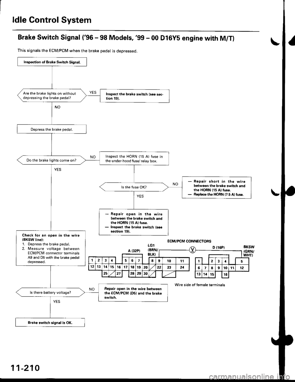
ldle Control System
Brake Switch Signal ('96 - 98 Models, '99 - 00 Dl6YS engine with M/Tl
This signals the ECM/PCM when the brake pedal is deoressed.
LGlBKSW(GRN/WHTI
D {16P)
Wire side of female t€rminals
Inspection of Brake Switch Signal.
Are the brake lights on withoutdepressing the brake pedal?
Depress the brake pedal.
Inspect the HORN (15 A) fuse inthe under-hood fuse/ relay box.Do the brake lights come on?
- Repair short in the wirebetween the brake 3whch andrhe HORN 115 At lu3e.- Replace the I|oRN 17.5 A) tus€.
Repair open in the wirebetween the brake switch andthe HORN 115 Al fuse.Inspect th6 br.ke switch {s6€section l9l.Check tor an open in the wireIBKSW line):1. Oepress the brake pedal.2. Measure voltage betweenECM/PCNI connector terminalsAg and D5 with the brake pedaloepresseo.
Repair open in the wire b€tweenthe ECM/PCM {Dsl and the brakeswitch.
ls there battery voltage?
Brakc switch sign.l is OK.
ECM/PCM CONNECTOFS
A (32PtIBRI\v
,la678101112I
121311151617t8192022232aI9101112
25212Aa3013141516
11-210
Page 484 of 2189
\
(From page 11'2141
Check lor a short in tho PSP
swhch:1. Turn the ignition switch OFF
2. Disconnect the 2P connector
from the PSP switch
3. Turn the ignition switch ON {ll)
4. Measure vohage between ECW
PCM connector terminals A26
and 820.
Ch6ck for a short in tho wiro IPSP
SW lino,:1. Turn the ignition switch OFF
2. Disconnect the ECM/PCM con-
nector A (32P).
3. Check for continuity betweon
body ground and ECM/PCM
connector terminal A26
Rogair short in the wiro b€{woon
the ECM/PCM (A26) and the PSP
switch.
Substitute a known_good ECM/
PCM rnd r.check. lf Prdcribodvohago is now avaihblo' rcPl.co
the original ECM/PCM
ECM/PCM CONNECTORS
ECM/PCM CONNECTOR A I32P)
Wire side of lemale terminals
Wire side of female terminals
'l'
5-21
Page 487 of 2189

ldle Control System
{
(
a
Clutch Switch Signal (Dl6YS engine with M/Tl
This signals the ECM when the clutch is engaged.
A {32P}
ECM CONNECTORS
LGl (BRN/BLK)
\-
cLsw(RED}
Inrpaction ot dutch rwitch signal.
Check for on opon in the wiro(CLSW linel:'!. Turn the ignition switch ON (ll).2. Measure voltage betweon ECt!4connector terminals C29 andA9.
Ch.ck tho clutch switch:1. Turn the ignition switch OFF.2. Disconnect the 2P connectorfrom the clutch switch.3. Turn the ignition switch ON (ll).4. Measure voltage b€tween ECMconnector terminals C29 and
ls thare approx. 5 V?
ls there approx. 5 V?
Check for a short in th6 wire(CLSW line)l1. Turn the ignition swirch OFF.2. Disconnect the ECM connector C (31P)trom the ECM.3. Check lor continuity betweenECM connector terminal C29and body ground.
Chcck for an open in thg wire{CLSW linel:1. Depress the clutch pedal.2. Moasure voltage between ECMconnector torminals C29 andA9.
Repair short in the wirc betweentho ECM {C291 and tho clurchswitch.
Sub3titutg a known-good ECMand rechock, It p.e3cribed vohagoi! now available, roplace the orig-inal ECM.
Wire side of female terminals
26189101l12t3'tat5l617l822
o
(To page 11-219)
11-218
!
Page 508 of 2189

JI
I
- Repair open or 3hort in the
wire bstw€er the lGM-Fl mainrolsy .nd the No. 31 STARTERSGNAL 17.5 A) tuse.- Reolace the No. 31 STARTER
SIGNAL (7.5 Al fu3o in the
unde.-dash tusg/rolav box.
ls there baftery voltage?
Chock lor !n open in the wit.
lFLn line)l1. Turn the ignition switch OFF
2. Disconnect the ECM/PCM con-
nector A (32P).
3. Check for continuity between
the PGM-FI main relay 7P con-
nectorterminal No. 1 and ECM/
PCM connector terminal A16.
Ropair op6n in th. walo betwoanthe ECM/PCM lA16) and thc
PGM-FI main rolaY.
Ch6ck for an opon in th. wi.e3
llcPl,lGP2linesl:1. Reconnect the ECM/PCN4 con-nector A (32P).
2. Reconnoct the PGM-Fl main
relay connector,3. Turn the ignition switch ON (ll)
4. Measure voltage between
ECM/PCM connector termanals
A11 and A10, and betweenA24 6nd A10.
Repeir opon in th6 wire bet-
ween ttre ECiA /PCM (A11, A24)
and tho PGM-FI msin r.lty.
R€plac. tho FGM-FI main rc|.Y.
Check tor an open in the ECM/
PCM:1. Turn the ignition switch OFF.
2, Measure voltage between
ECM/PCM connector terminalsA16 and A10 when the ignition
switch is lirst turned ON (ll) for
two seconds.
Substituta a known-good ECM/
PCM and rechcck. lf proacribod
voltege is now availablc, r.Placethe originll ECM/PCM.
ls thero 1.0 V or less?
Ch6ck th. PGM-FI m.in lolay(.ee pagc 11-2371.
('96 - 98 models)
t32Pt
Wire side of female terminals
IGP2{YEL/BLKI
FLRIGRN/YELIPGl
3l5 6 7l lslel tl1l
1213'tal5t6't7t8t920221 232a
2527284t
(cont'd)
1 1-239
IBLK)
{GRN/YELI
FLR(GRN/YELI
23
()a6t
ECM/PCM CONNECTOR A
21Il0t1
12r31'al5't61'tti9ml,/x2232a
25212e293ol./
PGl (BLK)
1I
12't/t15t617t8t9zi
25272A4t304l
Page 509 of 2189

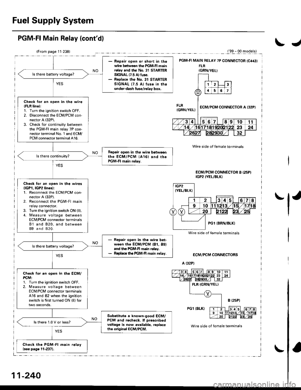
Fuel Supply System
- Repair op€n or short in thewir€ betlveen the PGM-FI mainrelay and the No. 31 STARTERSIGNAL 17.5 A) fuse.- RoDlace the No. 31 STARTERSIGNAL {7,5 Al tuse in theunder-dash luse/rolay box.
ls there battery voltage?
Check tor an open in the wire(FLR linel:1. Turn the ignition switch OFF.2. Disconnect the ECM/PCM con-nector A (32P).
3. Check for continuity betweenthe PGM-FI main relay 7P con-nector terminal No. 1 and ECM/PCM connector terminal A16.
Repair open in the wir6 botweenthe ECM/PCM (A161 and rhePGM-FI main relay.
Check for an open in the wires{lGPl, lGP2 line3):1. Reconnect the ECM/PCM con-nector A {32P).2. Reconnect the PGM-Fl mainrelay connector.3. Turn the ignition switch ON (ll).
4. Measure voltage betweenECN4/PCM connector terminals81 and 820, and betweenBg and 820.
- Repair open in the wire bet-ween th. ECM/PCM (81, Bg)snd the PGM-F main rolay.- Roplace th€ PGM-FI main relav.
Chock tor an open in th6 ECM/PCM:1. Turn the ignition switch OFF.2. Measure vo ltage betweenECM/PCM connector terminalsA16 and 82 when the ignitionswitch is first turned ON lll) for
Sub3titute . known-good ECM/PCM and rochock. lf prescribedvohege is now available, replacethe original ECM/PCM.
ls there 1.0 V or less?
Chock the PGM-Fl m.in r6lay{see p.ge 11-2371.
PGM-FI Main Relay (cont'd)
_._(9x . qq -gqerll _
PGM.FI MAIN FELAY 7P CONNECTOR {C4€}FLR
ECM/PCM CONNECTORS
A (32P1
Wire side ot female terminals
Wire side of fem6le terminals
ECM/PCM CONNECTOR B {25PIIGP2 {YEL/BLKI
IGRN/YEL}
IGP2(YEL/BLKI
Wire side of female terminals
11-240
IJ
'l'
Page 529 of 2189

Emission Control System
Exhaust Gas Recirculation (EGR) System (Dl6Y5 engine with CW) (cont'dl
tJ
(From page 11-259)EGR CONTROL SOLENOIDVALVE 2P CONNECTOR {C142}
Wire sideof lemaleterminals
ECMCONNECTORa t32Pl
Chock lor an open in the wire (E
SOL linsl:1. Turn the ignition switch OFF.2. Disconnect the 2P connectorIrom the EGR control solenoid
3. Disconnect the ECN4/PCM con-nector A (32P) (B (25P))* fromthe EcM/PCM.4. Check tor continuity betweenECM/PCl, connector terminal47 (86)* and the EGR controlsolenoid valve 2P connectorterminal No.2.
Repair opon in th. wir. bstwocntha EGR control 3ol€noid valvoand tho ECM/PCM (A7 186l'1.
ls there continuity?
Check for . rhort in the wire(ESOL linel:Check for continuity between theEGR controlsolenoid valve 2P con-nector terminal No. 2 and bodyground,
R.p.ir ahort in tha wi.c b.twecnthe EGR control iolonoid vllyeand th. ECM/FCM {A7 (46}rl.
Check for an opon in the wiroIGND linel:Check for continuity between theEGR controlsolenoid vaive 2P con-nector terminal No. I and bodyground,
Rcpai. op€n in the wir6 b6'twoenthe EGR control rol.noid valveand G101.
Sub3titule a known-good ECM/PCM and rechock. lf symptom/indication goes away, replac€the original ECM/PCM.
ESOL
IRED)
ESOLIRED)
Wire sideof femaleterminals--_-]
I
EGR CONTROL SOLENOIDVALVE 2P CONNECTOR ICl'2}
Wire sideof femaleilterminals
ECMCONNECTORB l25P)ESOL(REDI
Wire sideof femalerermtnats
*: '99 - 00 models
11-260
Page 533 of 2189

Emission Gontrol System
Exhaust Gas Recirculation System (Dl6Y5 engine with M/Tl (cont'dl
lFrom page 11 263)EGR VALVE6P CONNECTOR {C144}
J
Wire sideof femaletermtnals
J
Check lor an op€n in the wire (E-
EGR line):1. Turn the ignition switch OFF.2. Disconnect the ECM connector,A (32P)trom the ECM.3. Check lor continuity betweenECM connector terminal A7and the EGR valve 6P connec-torterminal No. 6.
Repair open in the wiro botweenthe EGR valv6.nd th€ ECM {A71.
Check tor a short in the wire {E-EGR lin6l:Check for continuity betweenECM connector terminal A7 andbody ground.
Reoair shorl in tho wiro belwe€nthe EGn vake rnd the ECM lA7l.ls there continuity?
Check fo. an open in tho wiro
IGND line):Check for continuity between theEGR valve 6P connector terminalNo.4 and body ground.
R6pai. open in th€ wir. betweenth6 EGF control solenoid v6lveand G101.
Substitute 8 known-good ECMand recheck. It symptom/indica-tion goes away, roplace the origi-nalECM.
CONNECTORA l32P)
2
a
I G101
Q) raur
-264