1996 HONDA CIVIC A 32p
[x] Cancel search: A 32pPage 427 of 2189

PGM-FI System
a
a
Heated Oxygen Sensor (HO2S) Heater
('96 - 98 Models,'99 - 00 D16Y5 engine with M/T) (cont'dl
PRIMARY HO2S {SENSOR 1I 4P CONNECTOR{c1231SECONDARY HO2S {SENSOR 2} 4PcoNNECTOR 1C125)r
r-l --'1
ll i2l
f;T;ttcl|BLK/ &)YELI Y
Wire side of fomale lerminals
SECONDARY HO2SISENSOR 2) 4P CONNECTOR{c78ilf
IBLK/WHT)
Wire side of lemale terminals
(From page 11-157)
Wire sid€ ot temale terminals
SO2HTC(BLK/WHTI* PO2SHTC{BLK/WHTI
*: P0141*+: Dl6Y8 engine
11-158
(From page 11-157)
Check tor an op6n or 3hoft in thewire {lGl lin6):Measure voltage between theHO2S 4P connector terminals No.3(D16Y8 engine: No. 4) and bodyground.- Repair open or shon in thewire between Primary HO2Slson.or 1), {No. 15 ALTERNA-TOR SP SENSORI (7.5 Al fuseand Secondary HO2S, Sonsol2t,.- Replace the No. 15 ALTERNA-TOR SP SENSOR 17.5 A) tuse.Check for an open in the wireIPO2SHTC, SO2SHTC' linel:1. Turn the ignition switch OFF.2. Reconnect the HO2S 4P con-nector.3. Disconnect the ECM/PCM con-nector A (32P).
4. Turn the ignition switch ON (ll).
5. Measure voltage between theECM,/PCM connector terminals46 and 410 {A5 and A10)*.
Ropail opan in the wire b€twoenECM/PCM lA6, A5l* and HO2S{Primary, Secondary+1.
ls there 0.1 V or less?
Substitute a known-good ECM/PCM and recheck. ll symptom/indication goes awry, repbcetho origin.l ECM/PCM.
ECM/PCM CONNECTOR A I32P)
so2sHrc ItBLK/WH0.J
pozsxtc E/
IBI-K/WHTI ^,-----{v}-|.=,|I
PG1IBLK}3u I JsTgT roll12r3t5t6Ittar920z2l 2321
25272A2i3o
Check tor a short in the wire{PO2SHTC. SO2SHTC* line):'1. Turn the ignition switch OFF.2. Disconnect the ECM/PCM con-nector A (32P1.
3. Check for continuity betweenthe ECM/PCM connector termi-nal 46 (A5)* and body ground.
Repair short in thg wire betwe€nECM/PCM lA6, A5*l .nd HO2S(P.im.ry, Socondary*).
Substitute a known-good ECM/PCM and recheck. It symptom/indicetion goes away, rophcethe original ECM/PCM.
Page 429 of 2189

PGM-FI System
Heated Oxygen Sensor (HO2S) Heater
('99 - 00 Models except D16Y5 engine with M/T)
(From page 11-159)
Substitute a known-good ECM/PCM and recheck. lf symptom/indication goes away, replacethe origin.l ECM/PCM.
(cont'dl
PRIMARY HO2S ISENSOR 1I 4P CONNECTOB{c123)SECONDANY HO2S ISENSOR 2} 4PcoNNECTOR (C125)*
-r--r ,
lr zl
-f-13 4llc'l L--r-J-r
relxr p1YELI Y
Wire side of temale terminals
SECONDARY HO2S(SENSOR 21 4P CONNECTOR{c782}rr
IG1 IBLK/WHT)
NO
Wire side of female telminals
ECM/PCM CONNECTORS
Wire side of female terminals
ECM/FCM CONNECTORS
*: P0141**: Dl6Y8 engine
1 1-1 60
Check for an open in the wires{lGl* line}iMeasure voltage between the primary HO2S 4P connector terminalNo. 3 (D16Y8 engine: No. 4) andbody ground.- Repeir open or shon in thewire between Primary HO2Slsensor 1), {No. 15 ALTERNA-TOR SP SENSOR) (7.5 A) fus€and Secondary HO2S, Sensor2t,.- ReDlace the No. 15 ALTERNA-TOR SP SENSOR {7.5 A tuse.
ls there battery voltage?
Check ,or an open in the wires(PO2SHTC, SO2SHTC' linel:1. Turn the ignition switch OFF.2. Reconnect the HO2S 4P con-nector,3. Disconnect the ECN4/PCM connector C (31Pi (ECM/PCM con-nector A (32P))i.
4. Turn the ignition switch ON (lli.
5. Measure voltage between theECM/PCM connector terminals82 and Cl 182 and AB)*.
Reprir open in the wirc betwo€nECM/PCM (Cl, A8i) and HO2S(Primary, Secondary+).
ls there 0.1 V or less?
(From page 11 l59i
Check tor a short in the wiresIPO2SHTC, SO2SHTC* linel:1. Turn the ignition switch OFF.2. Disconnect the ECM/PCM con-nector C (31Pi (ECM/PCM connector A (32P)i*.
3. Check tor continuity betweenthe ECM/PCM connector terminal C1 {A8)* and body ground.
Repai. short in the wire b€tweenECM/PCM lcl, A8.l and HO2S(Pdmery, Secondary*1.
Substitute a known-good ECM/PCM end recheck. lf symptom/indication goes away, replacethe o.iginal ECM/PCM.
Wire side of female terminals
Page 431 of 2189

PGM-FI System
I
a
a
Ch6ck the PO2SHTC circuit:1. Start engine and keep enginerpm at idle.2. At the engine wire harness,measure voltage betweenPrimary HO2S (Sensor 1) 8Pconnector terminal No. 1 terminal and body ground.
Check for an open in the wire(PG linellMeasurc voltage between PrimaryHO2S (Sensor 1) 8P connector ter-minals No. l and No.2.
ls there morethan 5 V?
Repair opon in the wi.o bEtwoonthe HO2S.nd G101 (located atth.rmonat housingl.
ls there more than 5 V?
Substitule a known-good ECM.nd .echeck. lt 3ymptom/indica-tion 906! rwry, roplace the origi-nal ECM,Check lor a short in the wire
{PO2SHTC line):1. Turn the ignition switch OFF.2. Disconnect ECM connector A(32P)trom the ECM.3. Check for continuity betweenECM connector terminal 46and body ground.
Ropair 3hort in tho wire betwoenthe ECM {46} and the Prim.ryHO2S lson3or 11.
Check for an open in the wire(PO2SHTC linel:Check for continuity betweenECM connector terminal 46 andthe Primary HO2S (Sensor 1)8Pconnector terminal No. 1.
Repair opsn in the wir6 botweenECM {A6} .nd the Primary HO2Slsonror 1).
Substituto a known-9ood ECMand rech6ck. lf symptom/indica-tion goes away, replace the origi-nal ECM.
Heated Oxygen Sensor (HO2S) Heater (Dl6Y5 engine with M/Tl (cont'd)
(From page 11-161)PRIMARY HO2S (SENSOR 1} 8P CONNECTOR {Cl45I
PO2SHTC{BtK/WHT)
PO2SHTCIALK/WHTI
ECM CONNECTOR
female terminals
11-162
\.
!
\
A {32P}
o
6I9l roIt
12t3l5t61't8t9a221 232a
252'2aEito,1| ---
Page 445 of 2189

PGM-FI System
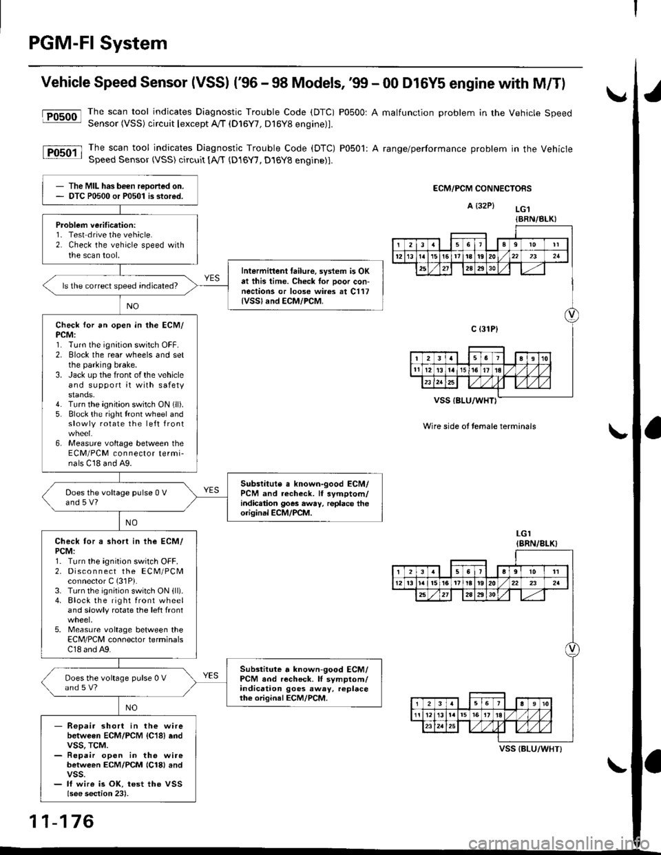
Vehicle Speed Sensor (VSSI ('96 - 98 Models,'99 - 00 D16Y5 engine with M/Tl
@The scan tool indicates Diagnostic Trouble Code (DTC) P0500: A malfunction problem in the Vehicle SpeedSensor (VSS) circuit Iexcept A!/T (D16Y7, D16Y8 engine)1.
The scan tool indicates Diagnostic Trouble Code (DTC) P0501: A range/performance problem in the VehicleSpeed Sensor (VSS) circuit [A,rT {D16Y7, D16Y8 engine)].
ECM/PCM CONNECTORS
A {32P} LG.t
VSS IBLU/WHT}
Wire side ot temale terminals
LGI(BRN/8LK}
The MIL has been reDorted on.DTC P0500 or P0501 is stored.
Problem verification:1- Test drive the vehicle.2. Check the vehicle speed withthe scan tool.
Intermittent tailure, system is OKat this time. Check tor Door con-nections or loose wires at C117{VSSland ECM/PCM.
ls the correct speed indicated?
Check for an open in the ECM/PCM:1. Turn the ignition switch OFF.2. Elock the rear wheels and setthe parking brake.3. Jack up the front of the vehicleand support it with safetystands.4. Turn the ignition switch ON (ll).
5. Block the right tront wheel andslowly rotate the left front
6, Measure voltage between theECM/PCM connector termi-nals C18 and A9.
Subslitute a known-good ECM/PCM and recheck. lf symptom/indic.tion goes away, replace theorisinal ECM/PCM.
Does the voltage pulse 0 Vand 5 V?
Check tor a short in ihe ECM/PCM:1. Turn the ignition switch OFF.2. Disco n n ect the ECM/PCMconnector C (31P).
3. Turn the ignition switch ON {ll).4. Block the right front wheeland slowly rotate the left front
5. Measure voltage between theECM/PCM connector terminalsC18 and A9.
Substitute a known-good ECM/PCM and recheck. lI symptom/indication goes away. replacethe original ECM/PCM.
Does the voltage pulse 0 Vand s V?
- Repair short in the wirebetwGen ECM/PCM {C18} endvss, TcM.- Repair open in the wirebetween ECM/PCM {Cl8} andvss.- lf wire is OK, test the VSSlsee section 23).
{BRN/BLK}
239l0lt
121611t8t9202321
2A2930
c {31P}
I38191o
tl12ialr5i6l10./
I2356a9l011
12l3l5t61tl8t920222a
27202930
12910
t2l13l.l7I l,/ 1,/231r.lslt., ),rlL
VSS {BLU/WHT}
11-176
Page 449 of 2189

PGM-Fl System
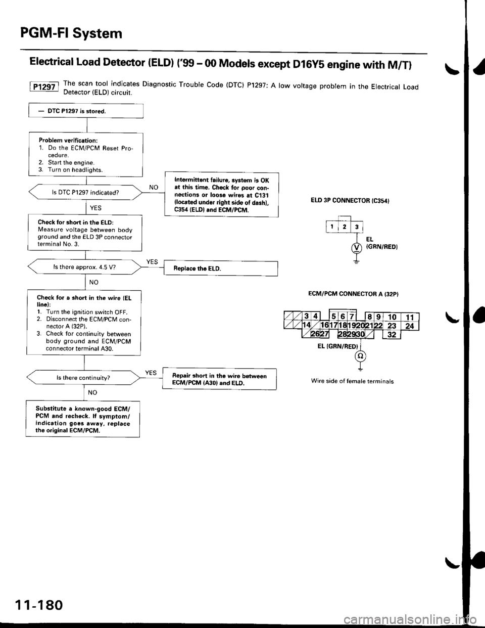
Elestrical Load Detector |ELD) t'glf - 00 Models except D16y5 engine with M/Tl
The scan tool indicates Diagnostic Trouble Code (DTC) P'1297; A low voltage probtem in the Electrical LoadDetector (ELD) circuit.
ELD 3P CONNECTOR tC354)
EL{GRN/REOI
ECM/PCM CONNECTOB A I32PI
Wire side of lemale terminals
Problem verilication:1. Do the ECM/PCM Reset Pro-cedure.2. Sta rt the engine.3. Turn on headlights.
Inlermittont failur6. systom i3 OKat this time, Chock tor ooor con-nestions or loose wires at C131(locrted undor ight side ot d.shl,C354 (ELDI and ECM/PCM.
Check for short in th6 ELD:Measure voltage between bodyground and the ELD 3P connectorterminal No.3.
ls there approx. 4.5 V?
Check to. a short in the wne (ELlinel:'L Turn the ignition switch OFF.2. Disconnect the ECM/PCM con-nector A (32P).
3. Check tor continuity betlveenbody ground and ECM/PCMconnector terminal A30.
Repair short in the wile betweenECM/PCM lA30) and ELD.ls there continuity?
Sub3titute a known-good ECM/PCM and rech€ck. It symptom/indication goes away. replacethe o.iginal ECM/PCM.
1 1-180
Page 451 of 2189

PGM-FI System
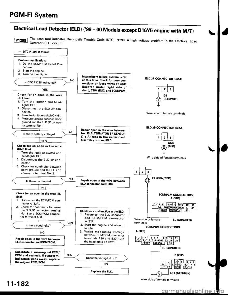
Elestrical Load Detector (ELDI ('99 - 00 Models except D16y5 engine with M/Tl
The scan tool indicates Diagnostic Trouble code (DTCI Pl298: A high vottage problem in the Etectrical LoadDetector (ELD) circuit.
ELD 3P CONNECTOR (65/0
EL {GRN/REOI
Wire side of fernale terminals
ELD 3P CONNECTOR (CA54I
TIr l2l3l
I crvo
(o) (BrKr
Y
Wire side of lemale terminals
ECM/PCM CONNECTORSA (32P1
Wire side of lemaleEI- IGRN/RED)terminals
ECM/PCM CONNECTORS
A {32P)
Problem ve.itication:1. Do the ECN4/PCM Reset pro
cedure.2. Start the engine.3- Turn on headiights.Inte.mittent teilu.e, svstem is OKat this lime. Chock for Door con-nections or loose wires at Ci31{located under Jight side otdaihl, C354 (ELD) and ECM/PCM.
ls DTC P1298 indicated?
Check for an open in the wire{lG1 line}:1. Turn the ignition and head-lights OFF.2. Disconnect the ELD 3P con
3. Turn the ignition switch ON (ll).4. Measure voltage between bodyground and the ELD 3P connec-torterminalNo. 1.
Repair opon in tho wiro batwe€nNo. 15 ALTERNATOR Sp SENSOR{7.5 A} fuse in th6 undor-dashIuse/reley box and ELD.
ls there battery voltage?
Check for an open in the wiro{GND linel:1. Turn the ignition switch andheadlights OFF.2. Disconnect the ELD 3P connector.3. Check for continuity betweenbody ground and the ELD 3Pconnector terminal No. 2,
Repair open in the wire bstwoenELD connsctor and Gia02.
Check ,or an open in the wire IELlinel:1. Disconnect the ECM/PCM con-nector A (32P).2. Check for continuity betweenthe ELD 3P connector terminalNo. 3 and ECM/PCM connec-tor terminal A30.
Chock fo. a malfunction in the ELD:'1. Reconnect the ELD connectorand ECM/PCM connectorA (32P).
2. Stan the engine and allow itto idle.3. While measuring voltagebetween ECM/PCM connectorterminals A30 and B2O, turnthe headlighrs on ow).
ls there continuity?
Repsir op€n in the wire betweenELD connector and ECM/PCM.
Substitute a known-good ECM/PCM and recheck. lf symptom/indication goes away. replacelh6 original ECM/PCM.
Does the vokage drop?
Wire side of f€male terminals
11-182
Page 463 of 2189

ldle Control System
ldle Air Control (lACl Vatve ('96 - 98 Dl6ys, Dl6yB engine with M/Tl
The scan tool indicates Diagnostic Trouble Code (DTC) P1508: A problem in the ldle Air Controt flAC) varvecircuit.
The IAC Valve changes the amount of air bypassing the throttle body in response to a current signal from the ECM inorder to maintain the proper idle speed.
IAC VALVE 2P CONNECTOR ICl3A)
,flrcerh-:J iYEL/BLKI
!.__-,/ -lt(v)
-T-=
Wire side of female terminals
tAcv(BLK/
ELUI
ECM CONNECTOR A I32PI
Wire side oI lemal€ terminals
VALVE
6a10ll12t3r5t6l7t8t920232a
t*25&a2A3o
The MIL hss b€on repo.ted on.DTC P'l508 i. itorod.
Problem vorification:1. Do the ECM/PCM Reset Pro-cedure,Start the engine, and warm ituP to normal operating tem-perature.
Intormittont t!llur., sy.tcm b OKat thb tim6. Chsck fol poor con-ncctionr or loo3e wirot at C138(lAC valv.l.nd ECM.
ls DTC P1508 indicated?
Check for an opcn in the wiro(lGPl line):1. Turn the ignition switch OFF.2. Disconnect the IAC valve 2Pconnector.3. Turn the ignition switch ON (ll).
4. Measure vohage between bodyground and the IAC valve 2Pconnectorterminal No. 2.
R.prir opan in the wiro botwa.nIAC valv..nd PGM-FI main r.l.y.
Chock for an opon or sho in thewire (IACV linal:1. Turn the ignition switch OFFand reconnect the IAC valveconnector.2. Disconnect the ECM connectorA (32P).
3. Turn the ignit;on switch ON (ll).4. Measure voltage betweenbody ground and ECM con-nector terminal A12.
(To page 1l-195)
11-194
Page 467 of 2189

ldle Control System
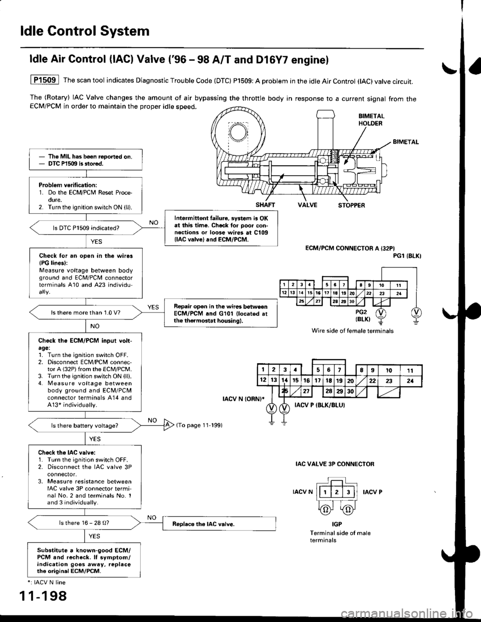
ldle Air Control (lAC) Valve ('96 - 98 A/T and Dl6Y7 enginel
The (Rotary) IAC Valve changes the amount of air bypassing the throttle body in response to a current signal from theECM/PCM in order to maintain the proper idle speed,
BIMETAL
VALVESTOPPER
1P1509 Thescantool indicates Diagnostic Trouble Code (DTC) P1509: A problem in the idle Air Control (tAC)valve circuit.
ECM/PCM CONNECTOR A I32PIPGl IBLKI
IAC VALVE 3P CONNECIOR
IACV NIACV P
IGP
Terminal side of maleterminals
*: IACV N line
1 1-198
The MIL has b€€n roported on.DTC P1509 is stored.
Problem verification:1. Do the ECM/PCM Reset Proce-oure.2. Turn the ignition switch ON (ll).
Intermittent failura, systom ia OKat this time. Check tor poo. con-noctions or loose wires at C109llAC valve) and ECM/PCM.
ls DTC P1509 indicated?
Check for an opon in the wirer{PG lines):Measure voltage between bodvground and ECM/PCII connectorterminals A10 and A23 individu
Repair op€n in the wires betwoenECM/PCM and G101 llocated attho thermostat housing).
ls there more than 1.0 V?
Chock th€ ECM/PCM inpui volt-agel1. Turn the ignition switch OFF.2. Disconnect ECM/PCM connec-tor A (32P)from the ECM/PCM.3. Turn the ignition switch ON (ll).4. Measu re voltage betweenbody ground and ECM/PCMconnector terminals A14 andA13* individually.
Ch6ck th6 IAC valve:1. Turn the ignition switch OFF.2. Disconnect the IAC valve 3Pconnector,3, Measure resistance betweenIAC valve 3P connector termi-nal No.2 and terminals No. 1and 3 individually.
ls there 16 - 28 g?
Substitute a known-good ECM/PCM and recheck. lf symptom/indication goos away, replaceth€ origin.l ECM/PCM.
SHAFT
rAcv N loRNl*
(To page 11-199)
Wire side of lemale terminals
123a56El011
121314r5161718t9202:22321
272AA30
IACV P {BLK/BLUI