Page 972 of 2189
t.
rl,
fl,
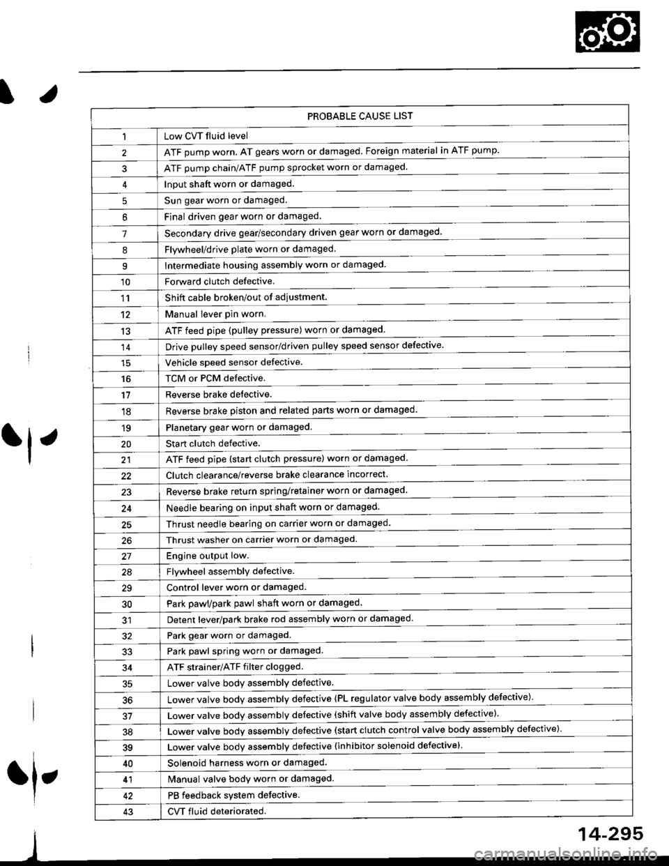
PROBABLE CAUSE LIST
Low CVT fluid level
ATF pump worn. AT gears worn or damaged. Foreign material in ATF pump.
ATF pump chain/ATF pump sprocket worn or damaged.
Input shaft worn or damaged.
Sun gear worn or damaged.
Final driven oear worn or damaqed,
Secondary drive gear/secondary driven gear worn or damaged-
5
6
1
8Flywheel/drive plate worn or damaged.
Intermediate housing assembly worn or damaged.9
'10Forward clutch defective.
Shift cable broken/out of adiustment.
M"nu"t t"uffi
ATF feed pipe (pulley pressure) worn or damaged.
Vchiclc speed sensor defective.
TCM or PCM defective.
Reverse brake detective.
1'�r
't2
13
14
16
'11
'18
1qPlanetary gear worn or damaged.
Sta rt clutch defective.
ATF feed pipe (start clutch pressure) worn or damaged
20
t't
Clutch clearance/reverse brake clearance incorrect.
23Reverse brake return spring/retainer worn or damaged
24Needle bearing on input shaft worn or damaged.
25Thrust needle bearing on carrier worn or damaged.
Thrust washer on carrier worn or damaged.
Enoine outout low.------------------------
Flvwhcel assemblv defective.
Control lever worn or damaged.
Park pawl/park pawl shaft worn or damaged
Detent lever/park brake rod assembly worn or damaged
27
29
30
32Park gear worn or damaged.
Park pawl spring worn or damaged.
ATF strainer/ATF filter clogged.
Lower valve body assembly defective.
Lower valve bodv assemblv defective (PL regulator valve body assembly defective)'
33
34
50
Lower valve bodv assembly defective (shift valve body assembly defective).
Lower valve bodv assemblv defective (start clutch control valve body assembly defective)'
39Lower valve bodv assemblv defective {inhibitor solenoid defective}
40Solenoid harness worn or damaged.
Manual valve body worn or damaged.
PB feedback system defective.
CVT fluid deteriorated.
41
43
14-295
Page 1071 of 2189
Component Locations
I
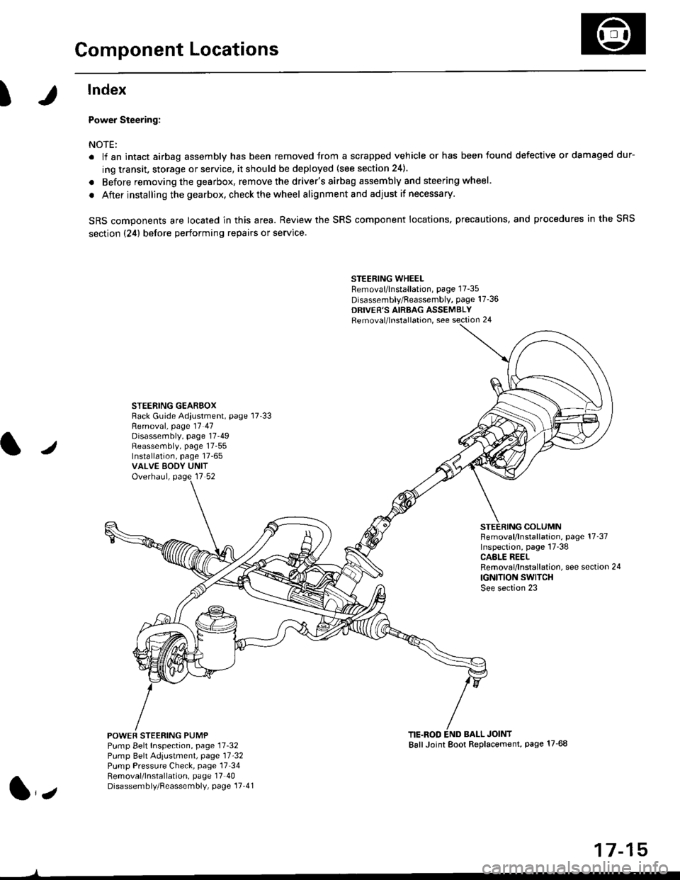
lndex
Power Steering:
NOTE:
. li an intact airbag assembly has been removed trom a scrapped vehicle or has been found defective or damaged dur-
ing transit. storage or service, it should be deployed (see section 24).
. Before removing the gearbox, remove the driver's airbag assembly and steering wheel.
. After installing the gearbox, checkthewheel alignmentand adjust if necessary.
SRS components are located in this area. Review the SRS component locations. precautions, and procedures in the SRS
section {24} before performing repairs or service.
STEERING WHEELRemoval/lnstallation, page 17-35
Disassembly/Feassembly, page 17-36
DRIVER'S AIRBAG ASSEMBLYRemoval/lnstallation, see section 24
STEERING GEAREOXRack Guide Adiustment, page 17'33
/
Removal, page 17 47Disassembly, page 17-49Reassembly, page 17-55Installation, page 17-65VALVE EODY UNITOverhaul, page 17 52
COLUMNFemoval/lnstallation, page 17-37Inspection, page 17-38CASLE REELRemoval/lnstallation, see section 24
IGNITION SWITCHSee section 23
POWEF STEERING PUMPPump Belt Inspection, page 11-32Pump Belt Adiustmenl, page 11'32Pump Pressure Check, page 17 34Removal/lnstallation, page 17'40Disassembly/Reassembly, page 17-41
TIE.ROD END BALL JOINTBallJoint Boot Replacement, page 17-68
1,,
17-15
Page 1438 of 2189
![HONDA CIVIC 1996 6.G Workshop Manual Troubleshooting
Compressor lcontdl
COMPRESSOR CLUTCH RELAY4P SOCKET
l--;l
12 |---r--]l.l3 |L-J--J
] BLK/YEL
A(v)
!
ECM/PCM CONNECTOR A I32P}
Wire side of female terminats
*Howto use the backprobe set HONDA CIVIC 1996 6.G Workshop Manual Troubleshooting
Compressor lcontdl
COMPRESSOR CLUTCH RELAY4P SOCKET
l--;l
12 |---r--]l.l3 |L-J--J
] BLK/YEL
A(v)
!
ECM/PCM CONNECTOR A I32P}
Wire side of female terminats
*Howto use the backprobe set](/manual-img/13/6068/w960_6068-1437.png)
Troubleshooting
Compressor lcont'dl
COMPRESSOR CLUTCH RELAY4P SOCKET
l--;l
12 |---r--]l.l3 |L-J--J
] BLK/YEL
A(v)
!
ECM/PCM CONNECTOR A I32P}
Wire side of female terminats
*Howto use the backprobe setsConnect the backprobe adapters to the stackang patch cords, andconnect the cords to a multimeter. Using the wire insulation as aguide for the contoured tip of the backprobe adapter, gently slidethe tip into the connector from the wire side until it comes in con-tact with the terminalend ofthe wire (see section 11).
Frcm page 22-12
To page 22-15
Check Ior an open in the wire;1. Disconnecl the jumper wire.2. Turn the ignition swatch ON (ll).
3. l\4easure the voltage betweenthe No. 4 terminal of the com-pressor clutch relay 4P socketand body ground.
Repair open in the wire betw€enthe No. 17 fuso and the compres-sor clutch relav.
Check for an open in the wira:1. Turn the ignition switch OFF,then reinstall the compressorclutch relay.2. Make sure the A/C switch isOFF, then turn the ignitionswitch ON (ll).
3. Using a *Backprobe Set (T/N07SAZ 0010004), measurethe voltage between the No.17 terminal oI the ECM/PCMconnector A (32P) and bodyground with the ECM/PCMconnectors connected.
Repair open in the wirc betweonthe compressor clutch relay andthe ECM/PCtvt.
ls there battery voltage?
Page 1440 of 2189
Troubleshooting
Gompressor (cont'dl
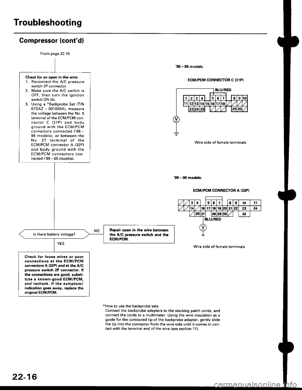
'96 -98 models:
ECM/PCM CONNECTOR C 13lPI
Wire side ot female terminals
'9!t - 00 mod.bi
ECM/PCM CONNECTOR A I32P)
Wire side ot female terminals
*How to use the backprobe setsConnect the backprobe adapters to the stacking patch cords, andconnect the cords to a multimeter. Using the wire insulation as aguide for the contoured tip of the backprobe adapter, gently slidethe tip into the connector from the wire side until it comes in con-tact with the terminal end ofthe wire {see section 11}.
From page 22-15
Check for an open in thg wire:'1. Reconnect the A"/C pressure
switch 2P connector.2. Make sure the A/C switch isOFF, then turn the ignitionswitch ON (ll).
3. Using a *Backprobe Set {T/N07SAZ - 001000A), measurethe voltage between the No. 5terminal of the ECM/PCM con-nector C (31P) and bodyground with the EcM/PcMconnectors connected ('96 -
98 models), or between theNo. 27 terminal of theECM/PCM connector A (32P)
and body ground with theECM/PCM connectors connected ('99 - 00 models).
Rapdir open in tho wi?e botwaonthe A/C pr..-ruro lwitch rnd th.ECM/PCM.
Check lor loo3e wires or ooolconnections at the ECM/PCMconnectoB A l32P) and at the A/Cpressure switch 2P connector, lfthe connections are good, substi-tute a known-good ECM/PCM,and recheck. lf the svmptom/indication goos away, repbce theoriginal ECM/PCM.
31501E91011
tat6l11E1921222321
BLU/RED
22-16
Page 1579 of 2189
Jlgnition Control Module (lCMl Input Test
NOTE:
. See section 1'l when the malfunction indicator lamp
(MlL) turned on.
. Perform an input test for the ignition control module
(lCM) after finishing the fundamental tests for the
ignition system and the fuel and emissions systems
1. Remove the distributor ignition (Dl) cap, the distrib-
utor ignition (Dl) rotor and the leak cover (TEC).
2. Disconnect the wires from the lCM.
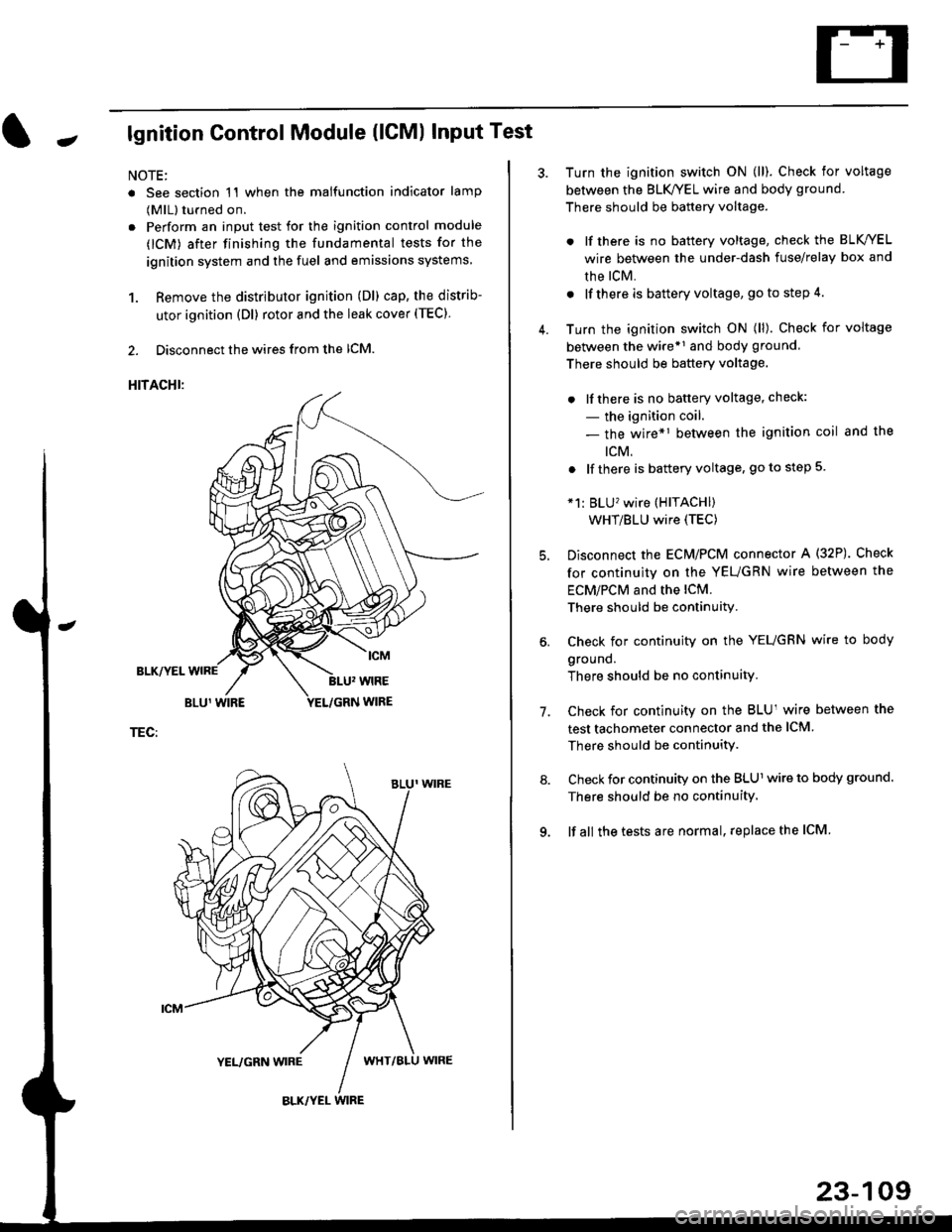
HITACHI:
BLK/YEL
TEC:
Turn the ignition switch ON (ll). Check for voltage
between the BLK/YEL wire and body ground.
There should be battery voltage.
. lf there is no battery voltage, check the BLK/YEL
wire between the under-dash fuse/relay box and
rhe lcM.
. lf there is battery voltage, go to step 4.
Turn the ignition switch ON (ll). Check for voltage
between the wire*r and body ground
There should be battery voltage.
. lfthere is no battery voltage, check:
- the ignition coil.
- the wire*1 between the ignition coil and the
tcM.
. lf there is battery voltage, go to step 5
*1: BLU'�wire (HITACHI)
WHT/BLU wire (TEC)
Disconnect the EcM/PCM connector A (32P). Check
for continuity on the YEUGRN wire between the
ECM/PCM and the lCM.
There should be continuity.
Check for continuity on the YEUGRN wire to body
ground.
There should be no continuity.
Check for continuity on the BLUl wire between the
test tachometer connector and the ICM
There should be continuitY.
Check for continuity on the BLUl wire to body ground.
There should be no continuity.
lf all the tests are normal, replace the ICM
7.
23-109
Page 1586 of 2189
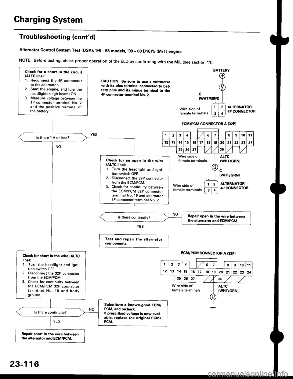
Charging System
Troubleshooting (cont'd)
Alternator Control System Test (USA): ,96 - 98 modets, ,99 _ 00 Dl6y5 (M/Tl engine
NorE: Before testing. check proper operation of the ELD by confirming with the MrL {see section r 1).
BATTERY
CAUTION: Be 3ure to use a voltmot€.with its plus terminal connected to b.t-tery plus and its minus terminal to the{P connectoi tgmrinal No. 2.c
{WHT/GRNt
Wire side oIfemale terminals
ALTERNATOR.P CONNECTOB
Check for a 3hort in the circuitIALTC linel:1. Reconnect the 4P connectorto the alternator,2. Stan the engine, and turn theheadlights {high beam) ON.3. Measure voltage between the4P connector terminal No. 2and the positive terminal ofthe battery.
ls there 1V or less?
Check for rn opon in tha wire(ALTC linol:1. Turn the headlight and igni-tion switch OFF.2. Disconnect the 32P connectortrom the ECM/PCN4.3. Check tor continuity betweenthe ECM/PCM 32P connectorterminal No. 19 and alternator4P connector terminal No. 2.
Bspair open in thg wire lrstweenthe rhern.tor .nd ECM/PCM.
Check for short in the wire (ALTClinel:1. Turn the headlight and ignition switch OFF.2. Disconnect the 32P connectortrom the ECM/PCM.3. Check tor continuity betweenthe ECM/PCM 32P connectorterminal No. 19 and bodyground.
Subslitute a known-good ECM/PCM, .nd .och6ck.It p.escribod vohago i! now avail-able, replace the original ECM/PCM.
Ropair 3hort in the wiro betweonthe ahe.nator and ECM/PCM.
ECM/PCM CONNECTOR A I32PI
'Ia18I1011
121314151718t9
7
202'l2221
262730
Wire side offemale terminalsALTC(WHT/GRNI
c{WHT/GRNI
ALTERNATORWire side oIfemale terminals
([l
T
12
1
ECM/PCM CONNECTOB A (32PI
I23478910t1
1213 14151617182021222321
262730
Wire side of I AITCfemate terminats
A
(WHT/GRN|
23-116