1996 HONDA CIVIC Front end
[x] Cancel search: Front endPage 1374 of 2189
Heater and Air Conditioning
Heater '.'..""" 21'1
Air Conditioning ......."'.. "' 22-1
SUPPLEMENTAL RESTRAINT SYSTEM (SRS}
The civic sRs includes a driver's airbag located in the steering wheel hub ln addition, all models (except some
models for canada) have a passenger's airbag located in the dashboard above the glove box'
Information necessary to safely service the sRS is included in this service Manual ltems marked with an asterisk (*)
on the contents page include, or are located near, sRs components. servicing, disassembling or replacing these
items will require special precautions and tools, and should therefore be done by an authorized Honda dealer'
@-";;il rendsring the SRS inoperative, which could lead to personal iniury or deaih in the svent of a sev€re
frontal collision. all SRS service work must be pertormed by an authorized Honda d€aler'
. lmploper service procedures, including incorrest removal and instsllation of the sRs, could lead to personal
iniury caused by unintentional deployment of the airbags'
o Do not bump the SRS unit. Otherwise. the system may fait in case of a collision. or the airbags may deploy
when the ignition switch is ON {ll}'
. sRs electrical wiring harncsses are id€ntified by yellow colol coding. Related components ale located in lhe
steering column, front console, dashboard, dashboald lowet panel, and in the dashboard above the glove box'
Do not use electricaltest equipment on these circuits.
Page 1512 of 2189
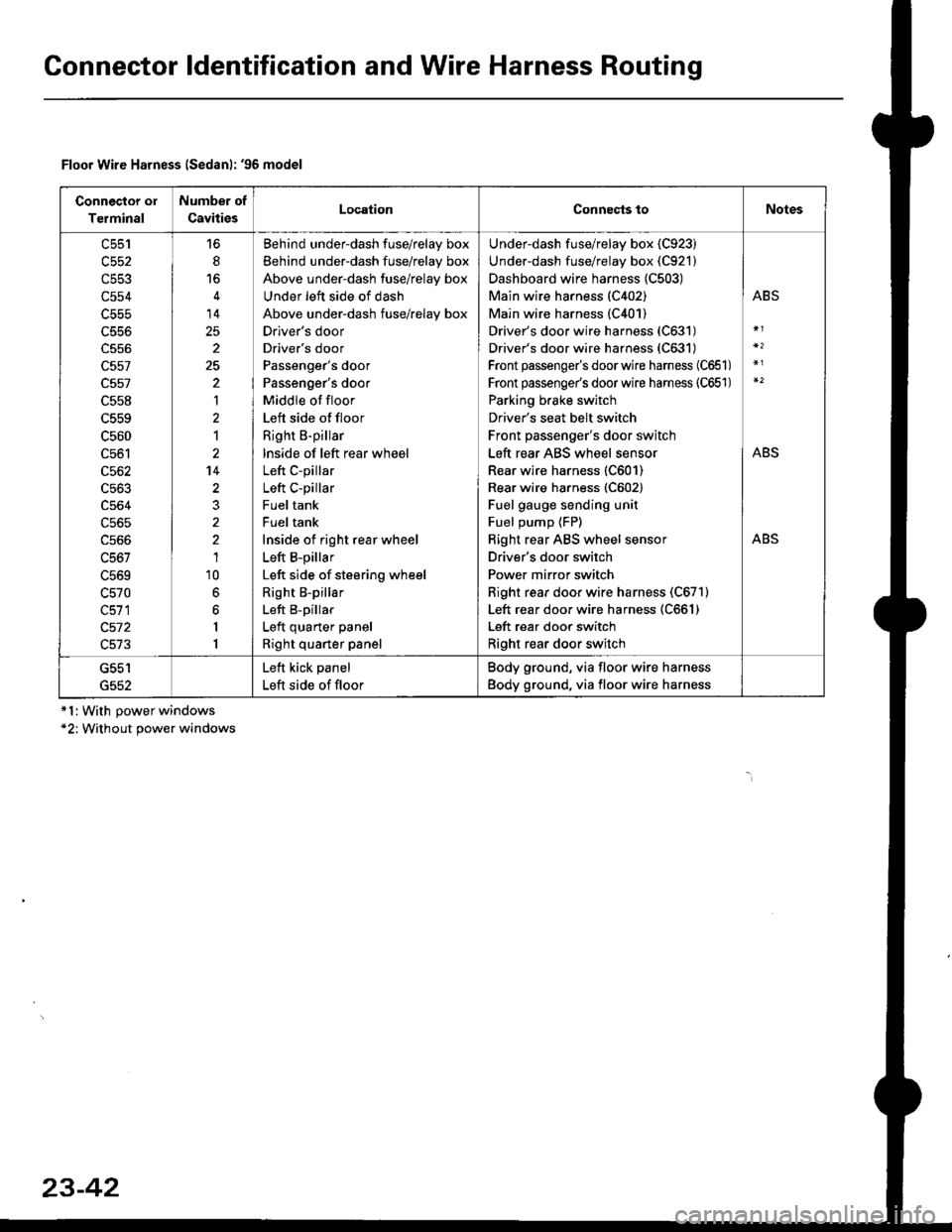
Gonnector ldentification and Wire Harness Routing
Connector ol
Terminal
Number of
CavitiesLocationConnects toNotes
c553
c554
c556
c557
c557
c558
c559
c560
c561
c562
c563
c564
c565
c566
c567
L5bY
c570
c511
c572
c513
6
14
25
2
25
'|
1
2't4
1'10
6
6
I
1
Behind underdash fuse/relay box
Behind under-dash fuse/relay box
Above under-dash fuse/relay box
Under left side of dash
Above under-dash fuse/relay box
Drlver's door
Driver's door
Passenger's door
Passenger's door
Middle of floor
Left side of floor
Right B-pillar
lnside of left rear wheel
Left C-pillar
Left C-pillar
Fuel tank
Fuel tank
Inside of right rear wheel
Left B-pillar
Left side of steering wheel
Right B-pillar
Left B-pillar
Left quarter panel
Right quarter panel
Under-dash fuse/relay box {C923)
Under-dash fuse/relay box (C921)
Dashboard wire harness (C503)
Main wire harness (C402)
Main wire harness (C401)
Driver's door wire harness (C631)
Driver's door wire harness (C631)
Front passenger's doorwire harness (C651)
Front passenge/s doorwire harness (C651)
Parking brake switch
Driver's seat belt switch
Front passenger's door switch
Left rear ABS wheel sensor
Rear wire harness (C601)
Rear wire harness (C602)
Fuel gauge sending unit
Fuel pump {FP)
Right rear ABS wheel sensor
Driver's door switch
Power mirror switch
Right rear door wire harness (C671)
Left rear door wire harness (C661)
Left rear door switch
Right rear door switch
ABS
ABS
ABS
G552
Left kick panel
Left side of floor
Body ground, via floor wire harness
Body ground, via floor wire harness
Floor Wire Harness lSedanl: '96 model
*l:With power windows*2; Without power windows
23-42
Page 1514 of 2189
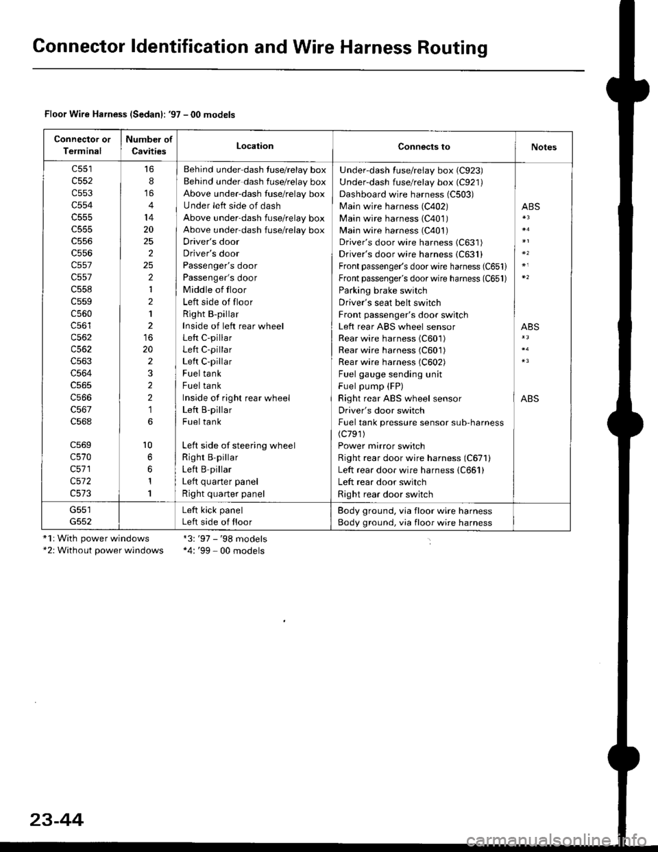
Gonnector ldentification and Wire Harness Routing
Floor Wire Harness (Sedanl: '97 - 00 models
Connector or
Terminal
Number of
CavitiesLocationConnects toNotes
c552
c553
c554
c555
c556
c557
c557
c558
c559
c560
c56'l
c562
c563
c564
c566
c568
c569
c570
c571
c572
16
8
14
20
25
2
2
1
2
1
20
2
2
2
1
l0
1
1
Behind under-dash fuse/relay box
Behind under dash fuse/relay box
Above under-dash fuse/relay box
Under left side of dash
Above under-dash fuse/relay box
Above under-dash fuse/relay box
Driver's door
Driver's door
Passenger's door
Passenger's door
Middle of floor
Left side of floor
Right B-pillar
Inside of left rear wheel
Left C-pillar
Left C-pillar
Left C-pillar
Fuel tank
Fuel tank
Inside of righr rear wheel
Left B-pillar
Fuel tank
Left side of steering wheel
Righr B,pillar
Left B pillar
I ofr ^,,.riar ^.^al
Right quarter panel
Under-dash fuse/relay box (C923)
Under-dash fuse/relay box (C921)
Dashboard wire harness (C503)
Main wire harness (C402)
Main wire harness (C401)
Main wire harness (C401)
Driver's door wire harness (C631)
Driver's door wire harness {C631}
Front passenger's door wire harness (C651)
Front passenger's door wire harness (C651)
Parking brake switch
Driver's seat belt switch
Front passenger's door switch
Left rear ABS wheel sensor
Rear wire harness (C601)
Rear wire harness (C601)
Rear wire harness (C602)
Fuel gauge sending unit
Fuel pump (FP)
Right rear ABS wheel sensor
Driver's door switch
Fuel tank pressure sensor sub-harness(c791)
Power mirror switch
Right rear door wire harness (C671)
Left rear door wire harness (C661)
Left rear door switch
Right rear door switch
ABS
ABS
ABS
G551Left kick panel
Left side of floor
Body ground, via floor wire harness
Body ground, via floor wire harness
"1r With power windows*2: Without power windows
*3:'97 - '98 models*4: '99 - 00 models
23-44
Page 1743 of 2189
Description
)
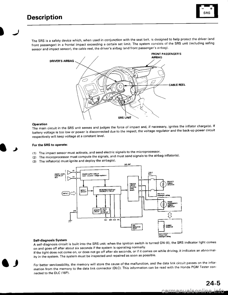
The sRS is a safety device which, when used in coniunction with the seat belt, is designed to help protect the driver land
front passenger) in a frontal impact exceeding a certain set limit. The system consists of the sRS unit {including safing
sensor and impact sensor), the cable reel, the driver's airbag (and front passenger's airbag)
FRONT PASSENGEB'SAIRAAG
DRIVER'S AIRBAG
CABLE REEL
SRS UNtT
t
Operation
The main circuit in the SRS unit senses and judges the force of impact and, if necessary, ignites the inflator charge(s) lf
battery voltage is too low or power is disconnected due to the impact, the voltage regulator and the back-up power clrcult
resoectivelv will keep voltage at a constant level.
For the SRS to operate:
(1) The impact sensor must activate. and send electric signals to the mlcroprocessor'
(2) The microprocessor must compute the signals' and must send signals to the airbag inflator(s)'
{3) The inflator(s) must ignite and deploy the airbag(s)'
_"-_-l
Ir3B!#h i
!.. I
ffi,*
Self-diagnosis System
A self-diagnosis circuit is built into the SRS unit; when the ignition switch is turned ON (ll), the SRS indicator light comes
on and goes off after about six seconds if the system is operating normally
lf the liglt does not come on, or does not go off after six seconds, or if it comes on while driving, it indicates an abnormal-
ity in the system. The system must be inspected and repaired as soon as possible
For better serviceability, the memory will store the cause of the malfunctlon, and the data link circuit passes on the infor-
mation from the memory to the data link connector (DLC). This intormation can be read with the Honda PGM Tesler con-
nected to the DLC (16P).
l,
24-5
Page 1767 of 2189
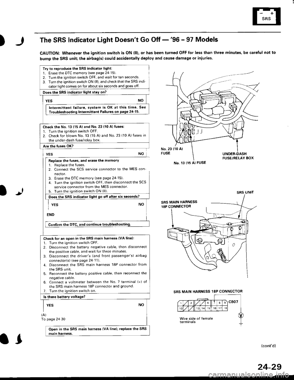
)The SRS lndicator Light Doesn't Go Off -'96 - 97 Models
CAUTION: Whenever the ignition switch is ON (ll), or has been turned OFF for less than three minutes, be careful not to
bump the SRS unit; the airbag{sl could accidentally deploy and cause damage or iniuries
Try to reproduce lhe SRS indicator light:
1. Erase the DTC memory (see page 24'15).
2. Turn the ignition switch OFF, and wait for ten seconds.
3- Turn the ignition switch ON {ll), and check that the SRS indi
cator light comes on for about six seconds and goes off
Does the SRS indicEtor light stay on?
[*NO
Intermittent lailure, system is OK at this time. See
Troubloshooting Int6rmittent Failures on page 24'15
Ch€ck the No. 13 {15 A} and No. 23 (10 A) fuses:
1. Turn the ignition switch OFF.
2. Check for blown No. 13 (15 A) and No.23 (10 A)fuses in
the under dash fuse/relay box.
Are the fuses OK?
vEs No
Replace the luses, and erase the memory1. Replace the fuses.2. Connect the SCS service connector to the MES con
nector.3. Erase the DTC memory (see page 24 15).
4. Turn the ignitaon switch OFF, then disconnect the SCS
service connector from the MES connector.5. Turn the ignition switch ON (ll).
Does the sRS indicato, tigt t go or "ne. "ii--JJl
-I YEs NO1
ENDi
Conlirm the DTC, and continue troubl6shootilg.
Check for an open in the SRS main harness {VA linell'1. Tu.n the ignition switch OFF.
2. Disconnect the battery negative cable, then disconnect
the positive cable, and wait for three minutes.
3. Disconnect the driver's (and front passenger's) airbag
connectorls) (see page 24 11).
4. Disconnect the SBS main harness '18P connector from
the sRS unir.5, Reconnect the battery positive cable, then reconnect the
negative cable.6. Connect a voltmeter between the No. 7 tetminal (+) of
the SRS main harness 18P connector and ground.
7. Turn the ignition switch on.
b there battery voltageT
YESNO
(A)
To page 24 30
Open in the SRS main harness IVA line); replace the SRS
main harness.
l.J
SBS MAIN
(cont'd)
No. 't3 {15 Al FUSE
SRS UNIT
HARNESS 18P CONNECTOR
II
24-29
Page 1777 of 2189
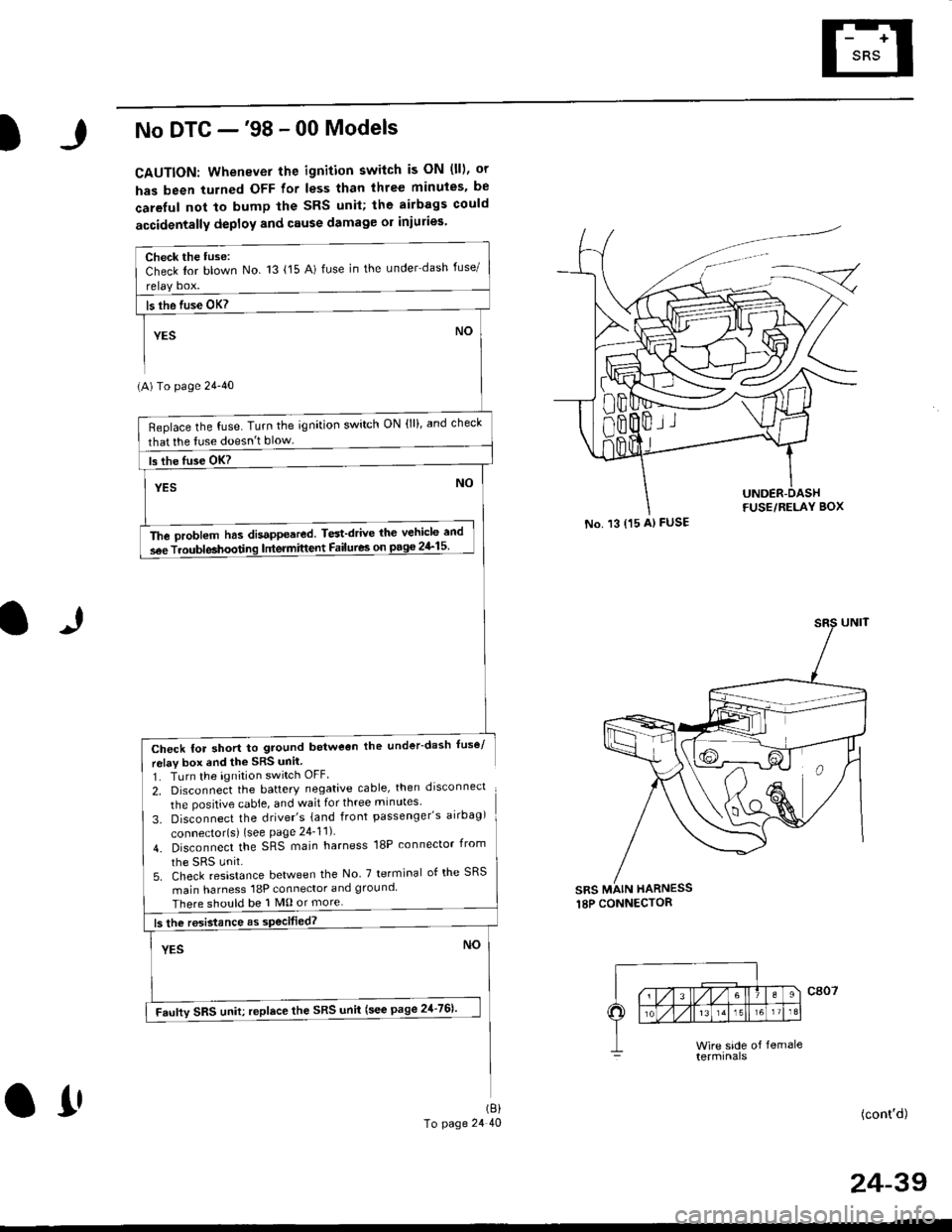
.J
No DTC -'98 - 00 Models
CAUTION: Whenever the ignition switch is ON (ll), or
has been turned OFF for less than three minuies. be
careful not to bump the SRS unil; the airbags could
accidentally deploy and cause damage or iniuries
(A) To page 24'40
Check for short to ground betweon the under-dash fuse/
relav box end the SRS unil
1. TLrrn the ignition switch OFF
2, Disconnect the battery negative cable, then drsconnect
the positive cable, and wait for three minutes'
3. Disconnect the driver's {and front passenger's airbag)
connector{s) {see Page 24_11)
4. Disconnect the SRS main harness 18P connector irom
5. Check resistance between the No 7 terminal of the SRS
main harness 18P connector and ground
There should be 1 M0 or more
(cont'd)
No. 13 {15 A) FUSE
sRs MAIN HARNESS
Check the tuse:Check Ior blown No 13 {15 A) fuse in the under dash fuse/
Beplace the fuse. Turn the ignition switch ON (lll, and check
that lhe tuse doesn't blow
The oroblem has disappeared. Test'drive thc vehicle and
s6e Troubleahoodng lntermittent Failures on pago 2&15
Faufty SRS uniu replace the SRS unii (see page 21-761'
(8)
To page 24 40O1'
24-39
Page 1781 of 2189
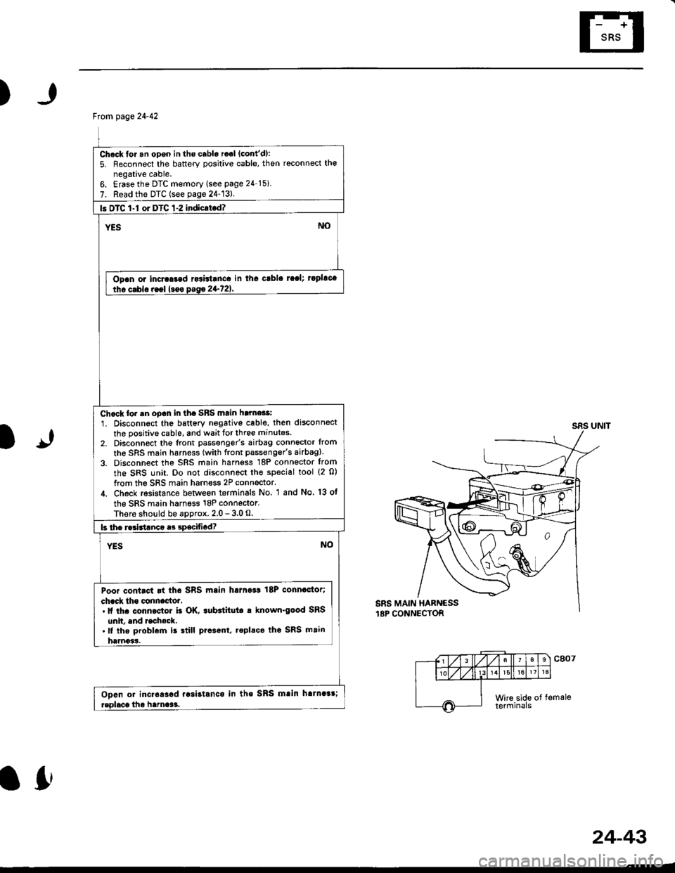
)
1J
From page 24-42
Check for an opgn in the cabl6 reel (cont'd):
5. Reconnect the battery positive cable, then roconnect the
negative cable.6. Erasethe DTC memory (see page 24 15i
7. Read the DTC (see page 24-13).
l. DTC 1-l or DTC 1-2 indicrt.d?
Opan or incraGad rcsbtanca in tha crbla raal; rapllca
Chcck lor .n oDcn in th. SBS mtin harne$i
1. Disconn€ct the battery negative cabl€, then disconnect
the positive cable, and wait tor three minutes
2, Disconnect the lront passgnger's airbag connoctor from
the SRS main harness (with front pssseng€r's airbag).
3. Disconnect the SRS main harn€ss 18P connector from
the SRS unit. Do not disconnect the special tool {2 0)
from the SRS main harness 2P connector.
4. Check resistance betlveon terminals No. 1 and No 13 ot
the SRS main harness 18P connector.
There should be approx. 2.0 - 3.0 O.
Poor contact rt tha SRS main harna*t 18P connactor;
chack tho clnnactot,. It th. conn.ctol b OK. tubttitut. a known-good SRS
unit. end rcchock..lf the problem is still prcsent, replace tho SRS main
harnoss.
Ooen or incr6asad r.si3tlnca in tha SRS mlin hatnaar;
lfr
24-43
Page 1808 of 2189
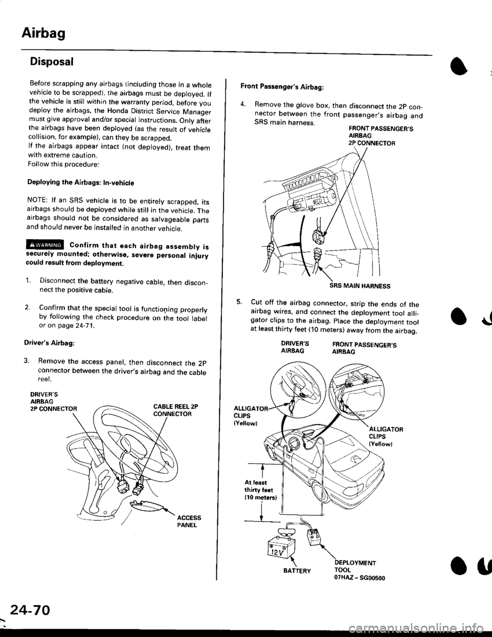
Airbag
Disposal
Before scrapping any airbags (including those in a wholevehicle to be scrapped), the airbags must be deployed. lfthe vehicle is still within the warranty period, before youdeploy the airbags, the Honda District Service Managermust give approval and/or special instructions. Onlv afterthe airbags have been deployed (as the result of vehiclecollision, for example), can they be scrapped.lf the airbags appear intact (not deployed). treat themwith extreme caution.
Follow this p.ocedure:
Deploying the Airbags: In.vehiclo
NOTE: lf an SRS vehicle is to be entirely scrapped, itsairbags should be deployed while still in the vehicle. Theairbags should not be considered as salvageable partsand should never be installed in another veh;cle.
!@ confirm thst oach airbag assembty issecurely mounted; otharwiso. sev€re personal iniurycould result lrom deployment.
1. Disconnect the baftery negative cable, then discon_nect the positive cable.
2. Confirm that the special tool is functioning properlyby following the check procedure on the tool labelor on page 24-'l'l .
Driver's Airbag:
3. Remove the access panel, then disconnect the 2pconnector between the driver,s airbag and the cablereet.
DRIVER'SAIRBAG2P CONNECTOR
24-70
BATTERY.U
Front Passenger's Airbag:
4. Remove the glove box, then disconnect the 2p con-nector between the lront passenger,s airbag andSRS main harness.FRONT PASSENGER'SAIREAG2P CONNECTOB
SRS MAIN HARNESS
Cut off the airbag connector, strip the ends of theairbag wires, and connect the deployment tool alli_gator clips to the airbag. place the deployment toolat least thirty feet (10 meters) away from the airbag.
a!
DRIVER'SAIRBAGFRONT PASSENGER'SAIRBAG
ALLIGACLIPS(Yellow)ALLIGATORCLIPS{Yellowl
At loastthiny toet(10 metorsl