1996 HONDA CIVIC Front end
[x] Cancel search: Front endPage 1142 of 2189
Front Damper
Disassembly/lnspection
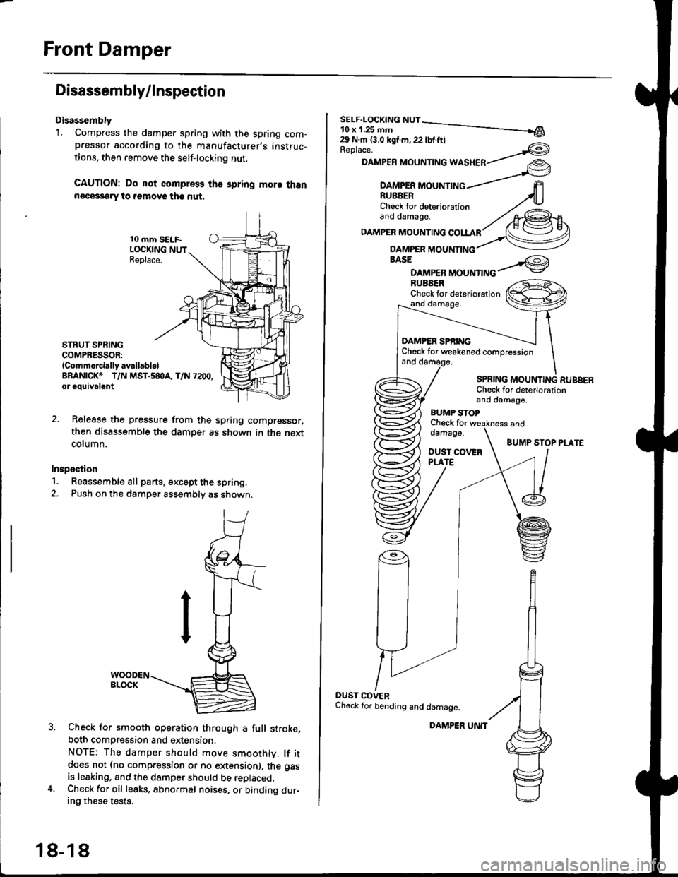
Disassembly'1. Compress the damper spring with the spring com-pressor according to the manufacturer,s instruc-
tions, then remove the self-lockino nut.
CAUTION: Do not compress the spring more thann€cessary to remove the nut.
10 mm SELF-LOCKING NUTReplace.
STRUT SPRINGCOMPRESSOR:(Commerci.lly availabl.lBRANICKO T/N MST.s8I}A, T/N 7200,or eouivalent
Release the pressure from thg spring compressor,
then disassemble the damper as shown in the next
column.
Inspostion
1. Reassemble all parts, except the spring.
2. Push on th€ damper assembly as shown.
Check for smooth operation through a full stroke,
both compression and extension,
NOTE: The damper should move smoothlv. lf itdoes not (no compression or no extension), the gas
is leaking, and the damper should be replaced.Check for oil leaks, abnormal noises, or binding dur-ing these tests.
18-18
DAMPER UNIT
Replace.
DAMPER MOUNTING WASHER
BASE
DAMPER MOUNTINGBUBBERCheck for deteriorationand damage.
DAMP€R SPf,INGCheck tor weakened compressionand damage.
SPBING MOUNTING RUBBERCheck for deteriorationand damage,
BUMP STOPCheck fordamage.
DUST COVERPLATE
and
BUMP STOP PLATE
OUST COVERCheck for bending and damage.
Page 1146 of 2189
Rear Suspension
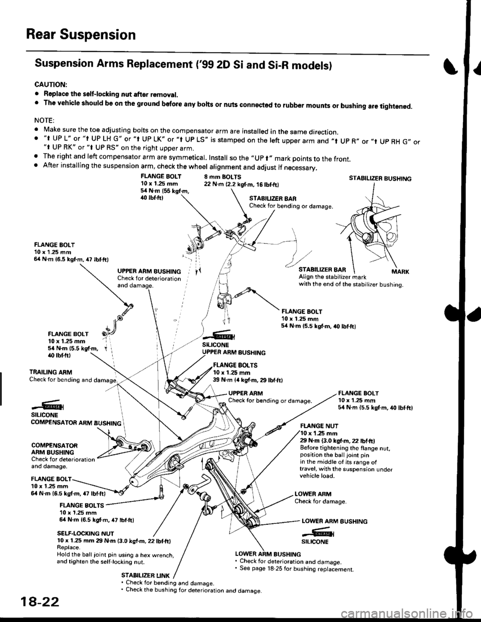
Suspension Arms Replacement ('gg 2D Si and Si-R models)
CAUTION:
. Roplace the self-locking nut after removal.' The vehicle should be on the gtound before any bohs or nuls connected to rubber mounts or bushing are tightened.
NOTE:
' Make sure the toe adjusting borts on the compensator arm are insta|ed in the same direction.. "t UP L" or "t UP LH G" or "t Up LK" or "l Up LS,, is stamped on the left upper arm and ,,t Up R,, or "t Up RH G,,"i UP RK" or "t UP RS" on the right upper arm.. The right and left compensator arm are symmeticar. Install sothe"upr"markpointstothefront.. After installing the suspension arm, check the wheel atignment and adiust if necessary,
FLANGE BOLT'10 x 1.25 mm54Nm155kgl.m,,rc lbf.ftl
8 rhm BOLTS22 N.m {2.2 kgf.m, 16 tbtfrlSTABILIZER BUSHTNG
FLANGE BOLT10 x 1.25 rnm54 N.m {5.5 kgt m, iro lbf.ft)
STAEILIZER BARCheck for bending or damage.
FLANGE BOLT10 x 1 .25 mm64 N m {5.5 kgf.m,47 lbtftl
FLANGE BOLT10 x 1.25 mm54 N.m 15.5 *gf.m,
and
UPPER ARM BUSHINGCheck for deteriorationAlign the stabitizer markwith the end ot the stabilizer bushing.
FLANGE BOLT'10 x 1.25 mm54 N.m 15.5 kgt.m, a0 lbtftl
stLrcoNEUPPER ARM BUSHINGiO lbf.ftl
TRAILING ARMCheck for bending and
EOLTS10 x 1.25 mm39 N m ll kgf.m, 29 lbf.ft)
UPPER ARMCheck for b€nding or damage.#@lstLtcoNECOMPENSATOR ARM BUSHING
COMPENSATORARM BUSHINGCheck for deteriorationand damage.
FLANGE NUTr '1.25 mm29 N.m {3.0 ksl.m,22 lbtft}Belore tightening the flange nut,position the ball joint pinin the middle ol its range oftravel, with the suspension undervehicle load.
LOWER ARMCheck for damage-
BUSHING
FLANGE BOLTl0 x 1.25 mm6l N.m 16.5 kg{.m, a7 lbt.ftl
FLANGE BOLTS10 x 1,25 mm64 N.m {6.5 kgf.m, 47 lbf.ftl
SELF.LOCKNG NUT
LOWER ARM
-GrstltcoNE10 x 1.25 mm 29 N.m (3.0 ksl.m, 22 tbtfrlReplace.Hold the ball ioinl pin using a hex w.enct.and tighten the selfjocking nut.
STABILIZEB LINK
LOWER ARM BUSHING. Check for deterioration and damaoe.' See page 18 25 for bushing replaciement.
' Check for bending and damage.. Check the bushing for deterioration ano oamage.
18-22
Page 1170 of 2189
Front Brake Galiper
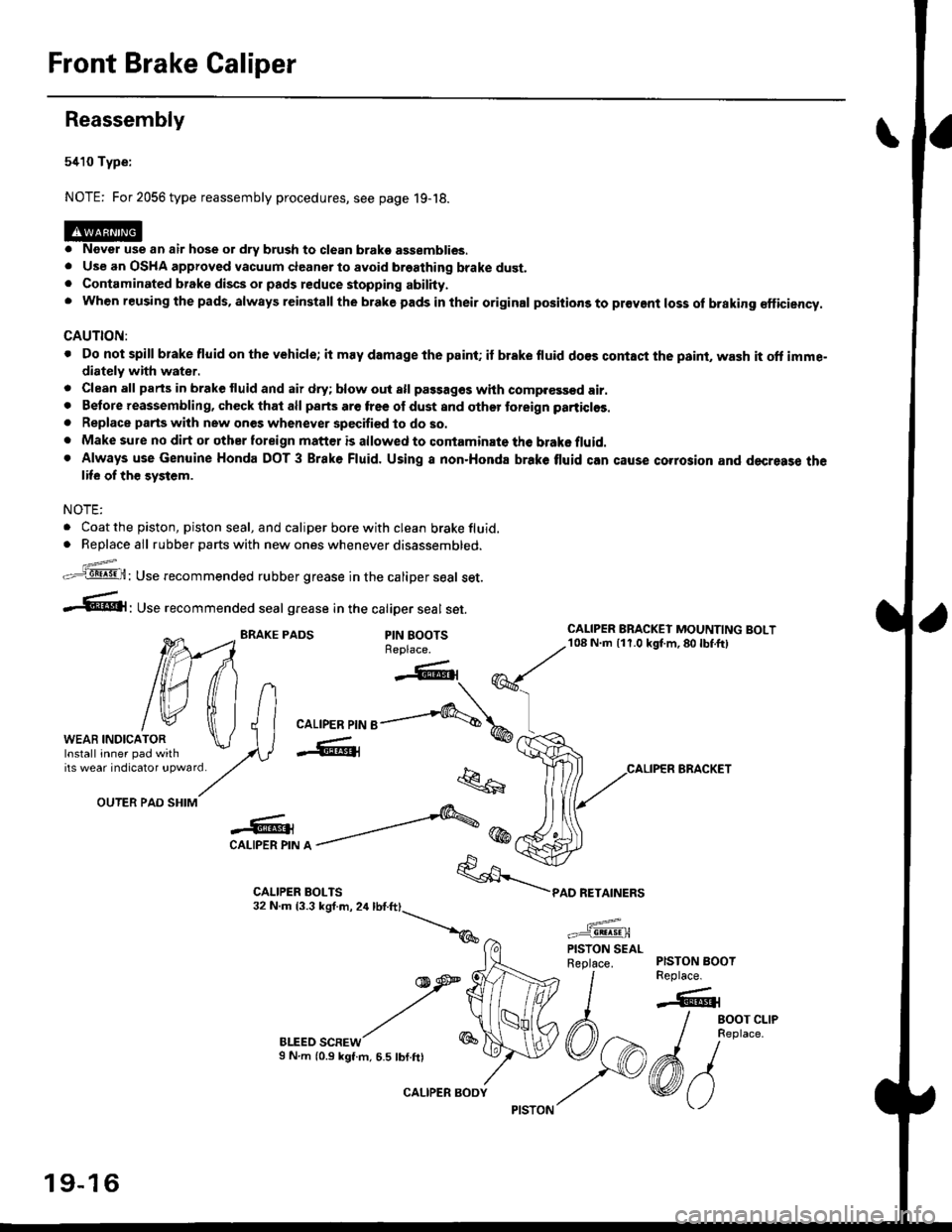
Reassembly
5410 Type:
NOTE: For 2056 type reassembly procedures, see page 19-18.
o Never use an air hose or dry brush to clean brako assemblies.. Use an OSHA approved vacuum cleanerto avoid breathing brake dust.. Contaminated brake discs or pads reduce stopping abilhy.. when reusing the pads, always reinstall the brake pads in their original positions to pr€vent loss of braking €fficiency.
CAUTION:
. Do not spill brake fluid on the vehicle; it may damage the paint; if brake fluid do€s contaci the psint, wash it oft imme"diately with water.
. Clean all parts in brake fluid and air dry; blow out all passag€s whh comp.€ssed air.. Betore reassembling, check that all parts are free ol dust and othor toreign particlos.
. Replace parts wilh new ones whenever specified to do so.. Make sure no dirt or other toreign matt€r is allowed to contaminate the brake fluid.. Always use Genuine Honda DOT 3 Brake Fluid. Using a non.Honda brake tluid can cause corrosion and decresse thelife of th€ system.
NOTE:
. Coat the piston, piston seal, and caliper bore with clean brake fluid.. Replace all rubber parts with new ones whenever disassembled.
z_..=-.q8! .9!,H: Use recommended rubber grease in the caliper seal set.
-.61' use recommended seal grease in the catiper seal set.
BRAKE PADSPIN BOOTSReplace.
OUTER PAD SHIM
-o -'''---&@CAI-IPER PIN A -
BLEED SCREWS N.m (0.9 kgt.m, 6.5 tbf.ftl
"k..6
*/\*
car-rpen prr'r e-....,-q\,
-W@{
q
1
PAD RETAINERS
CALIPER BRACKET
WEAB INDICATOR
tilfliltn
tw tfi lJlWEAB rNDrcAroR \J I Ilnsrall inner pad with lAVirs weat indicatot !pwatd/,.
CALIPER BRACKEI MOUNTING BOLT108 N.m {11.0 kgt m,80lbf.ft)
PISTON BOOTReplace.
-6r
/ eoor cr-re
I neptace.
6/vo
PISTON SEALReplace.
19-16
CALIPER BODY
Page 1172 of 2189
Front Brake Caliper
Reassembly (cont'd)
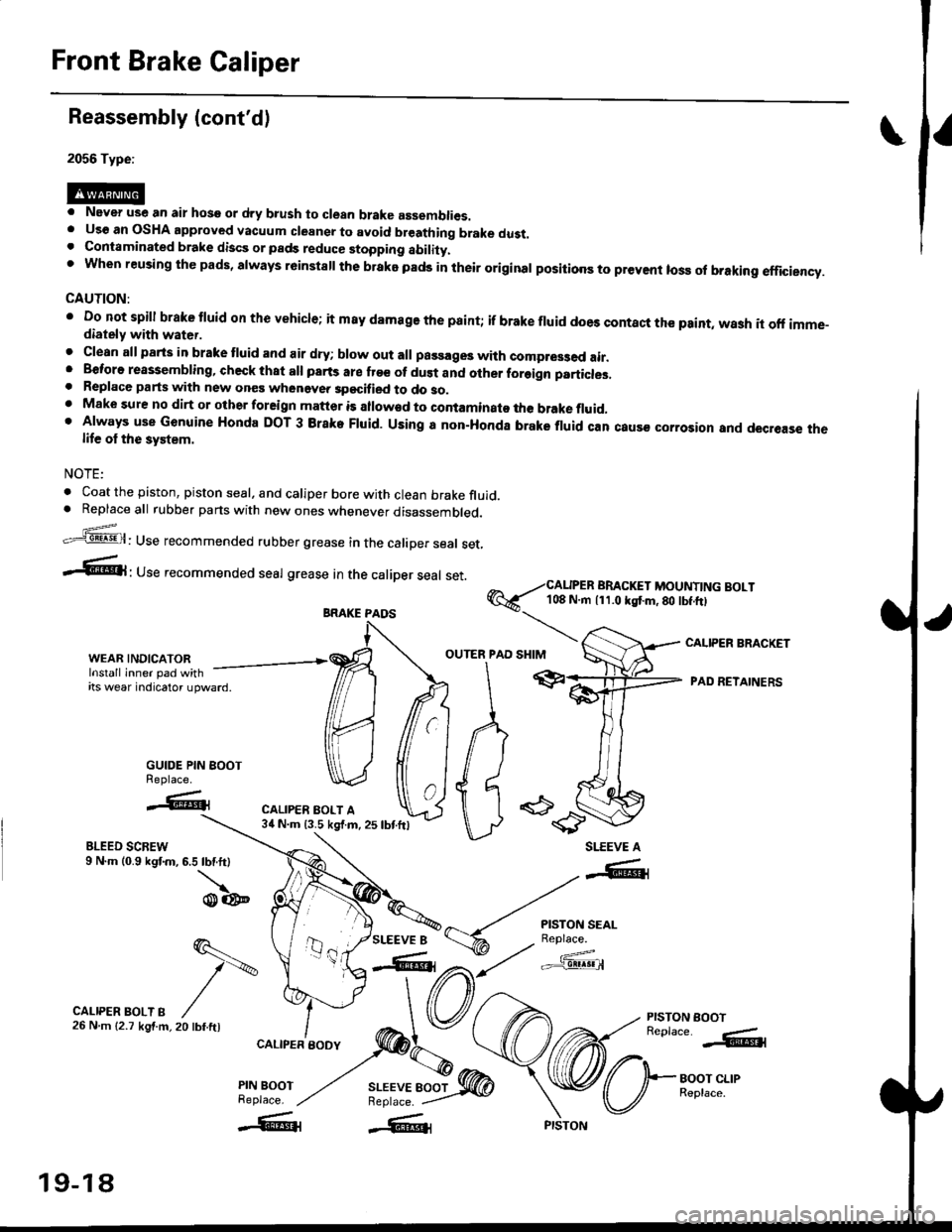
2056 Type:
. Never use an air hose or dry b.ush to clean brake assemblies.. Uso an OSHA approved vacuum cleansr to avoid breathing brake dust.. Contaminated brake discs or pads reduce stopping ability.t when reusing the pads, always r6instsll the brake pads in their original positioos to prevent loss ol braking efficiency.
CAUTION:
' Do not spill brake tluid or th€ vehicle; it m8y damage the paint; if brake fluid does contact the paint, wash it off imme-diately with water.
. Clean all parts in brake tluid and air dry; blow out all passages with compr63ed air.. Beforo reassembling, check that all parts are fr€e of dust and other foreign particles,. Replace parts with new ones whenevea specified to do so.. Make sure no dirt or other foreign matter is allowad to contaminato the brake fluid,' Always use Genuine Honda DOT 3 Brake Fluid. Using a non-Honda brake fluid can caus€ corrosior and decrease thelife ol the system.
NOTE:
. Coat the piston, piston seal, and caliper bore with clean brake fluid.. Replaceall rubber parts with new ones whenever disassembled.
.'=5@: Use recommended rubber grease in the caliper seal set,
-6l ' Use recommended seal grease In the caliper seal set.
@6--i#i['i,?li"..;:l]l?Y]li"'"'
I
r""'"rr r"""ip"autr, -/ffr
e"6ft 'ADRETATNERSitswearndcatoru'ward
MffiA pr
GUIDE PIN BOOT ) {I I II ) I I
% caL,PER
\I\d/ tt ' id 6
u -es'---r..'.* ".-,."oo*'J.l, ru,oonW U
**=*t
WEAR,INDICAToR. ,ffi OUTERIPAD
BLEED SCREW9 N.m (0.9 kgf.m, 6.5 lbf.ft)
\o@
CALIPER BRACKET
PISTON EOOTReplace. -.&l
BOOT CLIPReplace.
SLEEVE A
SLEEVE 8
-"-41
r{.i'""Jg*'
a,t/ c'f3!@
q.-
t\
20 tbf.ftl
CALIPER BOLT B26Nm{2.7kgf.m,
CALIPER BODY
PIN BOOTReplace.
BRAKE PAOS
19-18
Page 1174 of 2189
Front Brake Caliper
Reassembly (cont'dl
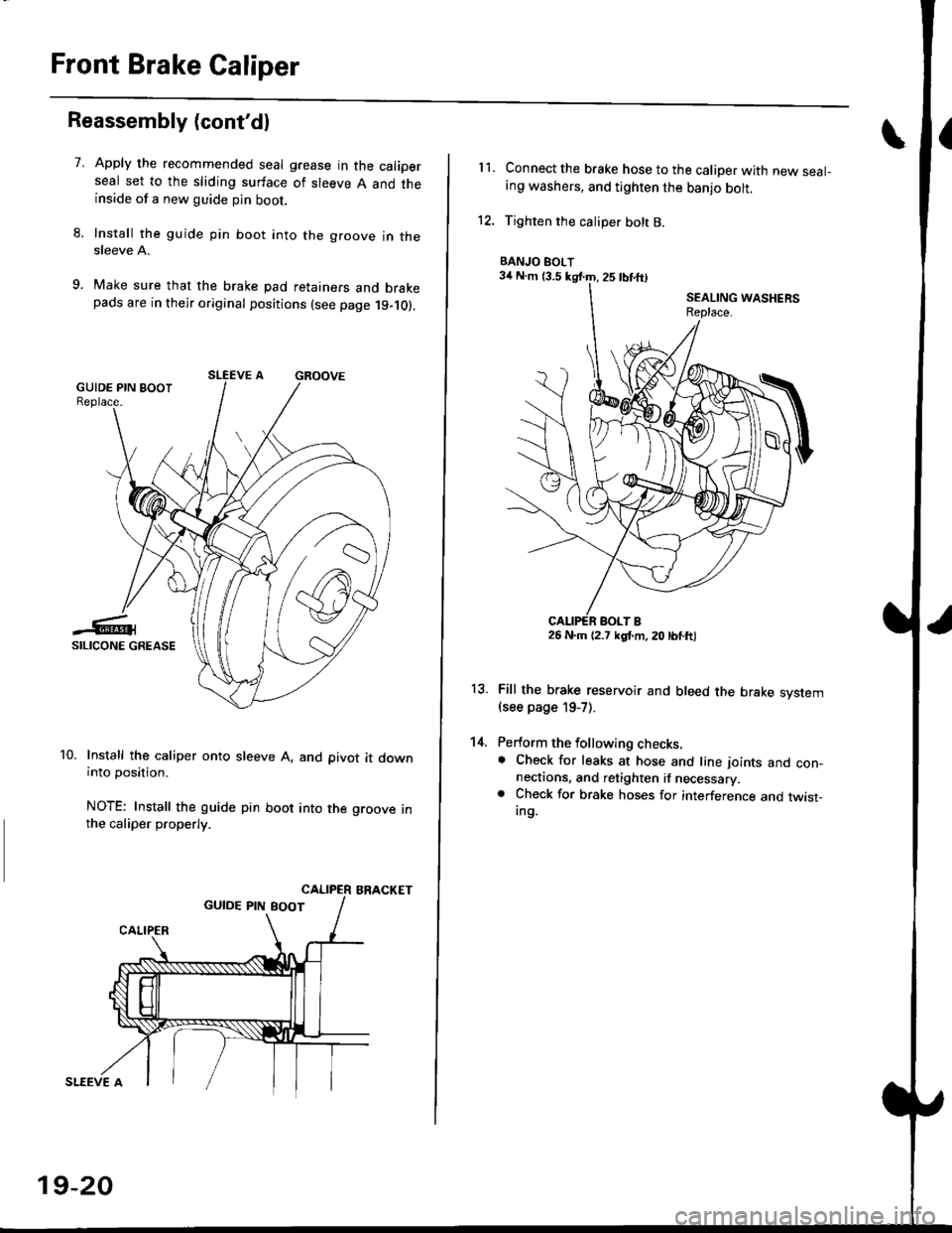
7.Apply the recommended seal grease in the caliperseal set to the sliding surface of sleeve A and theinside of a new guide pin boot.
Install the guide pin boot into the groove in thesleeve A.
Make sure that the brake pad retainers and brakepads are in their original positions (see page 19-10).
Install the caliper onto sleeve A, and pivot it downinto position.
NOTE: Install the guide pin boot into the groove inthe caliper properly.
BRACKET
SLEEVE A
19-20
11.Connect the brake hose to the caliper with new seal-ing washers, and tighten the banjo bolt.
Tighten the caliper bolt B.
Fill the brake reservoir and bleed the brake svstem(see page 19-7).
Perform the following checks.. Check for leaks at hose and line ioints and con-nectaons, and retighten if necessary.. Check for brake hoses for interference and twist-Ing.
13.
14.
BANJO BOLT
26 N.m (2.7 kgl.m, 20 lbtftl
Page 1175 of 2189
Master Cylinder/Brake Booster
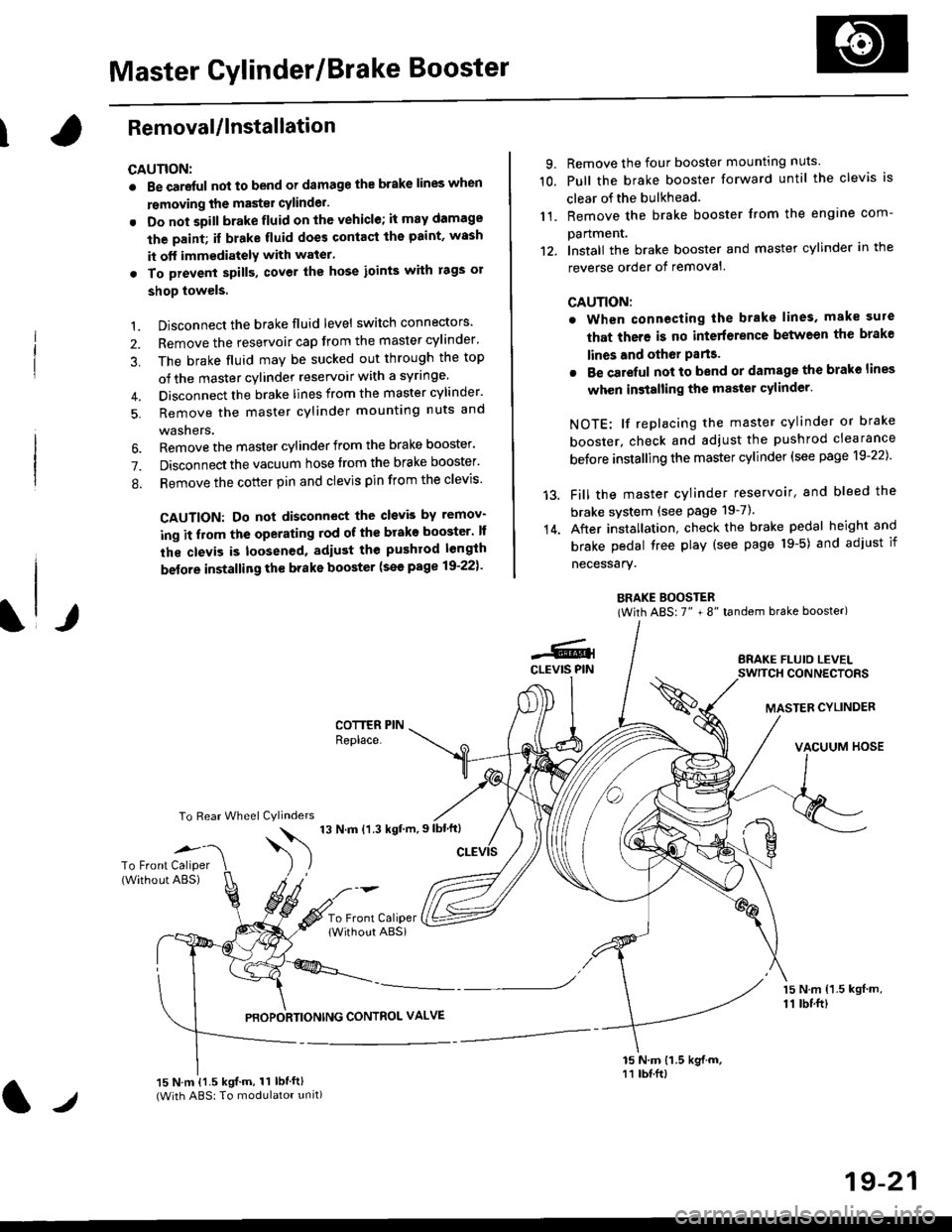
IRemovaUlnstallation
CAUTION:
. Be care{ul nol to bend or damage the brake lines when
rsmoving the mastsr cYlinder.
. Do not soill brakefluid on the vehicle; it may damage
the paint; if brake fluid does contact the paint, wssh
it off immediatelY with water'
. To prevent spill3, cover the hose ioints with rags or
shop towels.
9. Remove the four booster mountlng nuts
10. Pull the brake booster forward until the clevis is
clear of the bulkhead.
11. Remove the brake booster from the engine com-
panmenr.'12. Install the brake booster and master cylinder in the
reverse order of removal.
CAUTION:
. When connecting the brake lines. make sure
that there is no inte erence between the brake
lines and oth6r Parts.
r Be careful not to bend or damage the brake lines
when installing the master cylinder.
NOTE: lf replacing the master cylinder or brake
booster, check and adiust the pushrod clearance
be{ore installing the master cylinder (see page 19-221'
Fill the master cylinder reservoir, and bleed the
brake svstem (see Page 19-7).
After installation. check the brake pedal height and
brake pedal tree play (see page l9-5) and adjust if
necessary.
BRAKE BOOSTER(With ABS: 7" + 8" tandem brake booster)
BRAKE FLUIO LEVELSWITCH CONNECTORS
MASTER CYLINDER
VACUUM HOSE
1.
2.
3,
5.
Disconnect the brake fluid level switch connectors'
Remove the reservoir cap from the master cylinder'
The brake fluid may be sucked out through the top
of the master cylinder reservoir with a syrlnge.
Disconnect the brake lines from the master cylinder'
Remove the master cylinder mounting nuts and
washers.
\l/
6. Remove the master cylinder from the brake booster'
7. Disconnect the vacuum hose trom the brake booster'
8. Remove the cotter pin and clevis pin from the clevis'
CAUTION: Do not disconnect the clevb by remov-
ing it from the operating rod of the brako booster' lf
the clevis is loosened, adiust the pushrod length
before installing th€ brake booster (see page 19-221'
COTTER PINReplace.
To Rear Wheel Cylinders
14.
-6.4CLEVIS PIN
To Front Caliper(Without ABS)$
t'N't'ttrnt'-''
To Front CaliperlWithout ABSi
PBOPORTIONING CONTROL VALVE
15 N.m {1.5 kgl m,11 tbtft)
15 N.m {1.5 kgif.m, 11 lbtft}(With ABS: To modulator unit)lr
19-21
Page 1253 of 2189
bPosition Adjustment
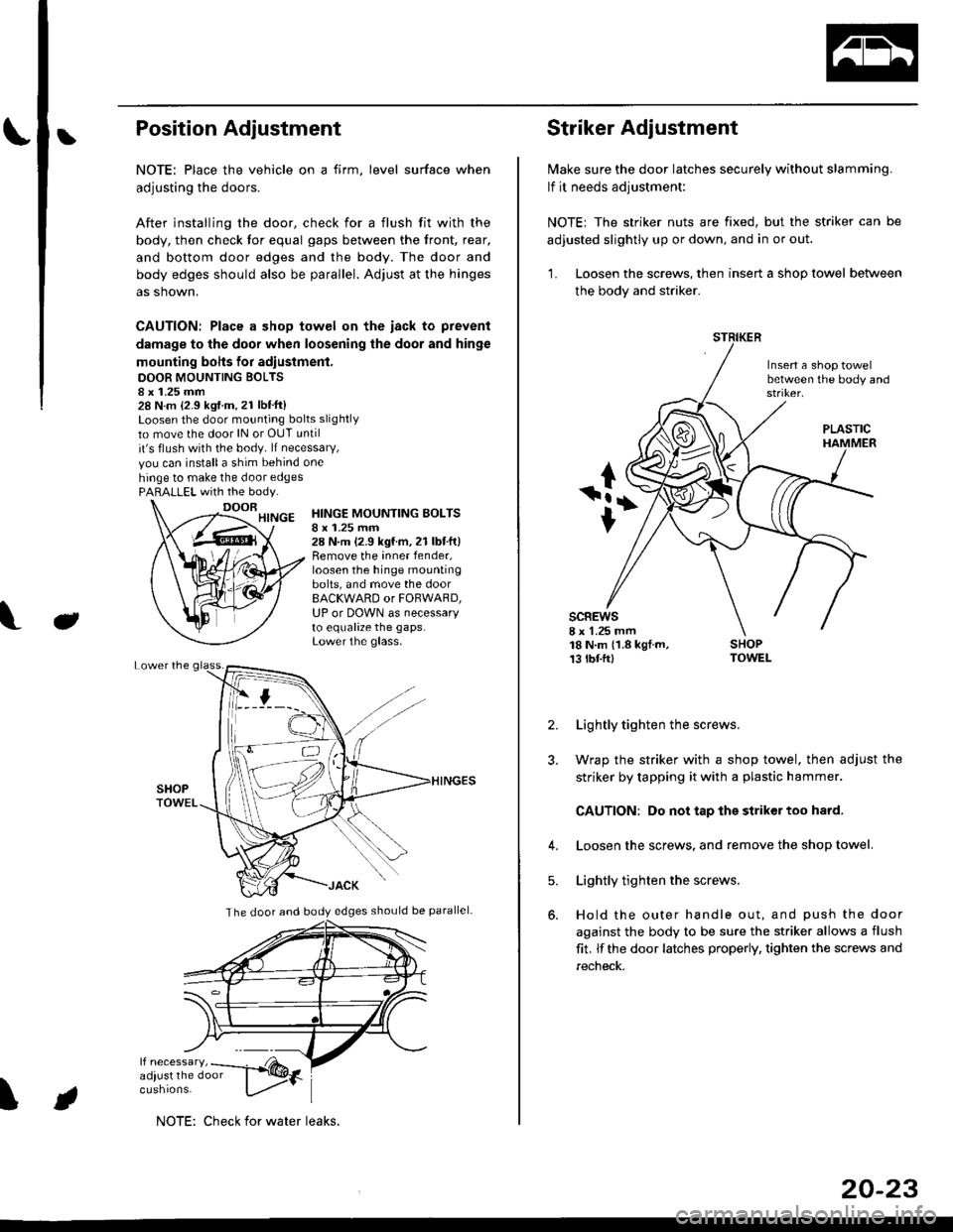
NOTE: Place the vehicle on a firm, level surface when
adjusting the doors.
After installing the door, check for a flush fit with the
body, then check for equal gaps between the front, rear,
and bottom door edges and the body. The door and
body edges should also be parallel. Adjust at the hinges
as shown,
CAUTION: Place a shop towel on the iack to prevent
damage to the door when loosening the door and hinge
mounting bohs for adiustment.
DOOR MOUNTING BOLTS8 x 1.25 mm28 N.m {2.9 kgf.m.21 lbt'ft}Loosen the door mounting bolts slightly
to move the door lN or OUT until
it's flush with the body. lf necessary,
vou can installa shim behind one
hinge to make the door edgesPARALLEL with the body.
J
HINGE MOUNTING BOLTSI x 1.25 mm28 N.m (2.9 kgf.m,21 lbtft)Remove the inner fender,loosen the hinge mountingbolts, and move the doorBACKWARD or FORWARD,UP or DOWN as necessaryto equalize the gaps.Lower the glass.
\
The door and body edges should be parallel-
ifF t
NOTE: Check for water leaks.
20-23
Striker Adjustment
lvlake sure the door latches securely without slamming.
lf it needs adjustment:
NOTE; The striker nuts are fixed, but the striker can be
adjusted slightly up or down, and in or out.
'L Loosen the screws, then insert a shop towel between
the body and striker.
Insert a shop towelbetween the body and
sc8Ews8 x 1.25 mm18 N.m (1.8 kgf.m,13 tbtftl
PLASTIC
2. Lightly tighten the screws.
3. Wrap the striker with a shop towel, then adjust the
striker by tapping it with a plastic hammer.
CAUTION: Do not tap the striker too hard.
4. Loosen the screws. and remove the shop towel.
Lightly tighten the screws.
Hold the outer handle out, and push the door
against the body to be sure the striker allows a flush
fit. lf the door latches properly, tighten the screws and
recheck.
5.
Page 1258 of 2189
Windshield
Removal
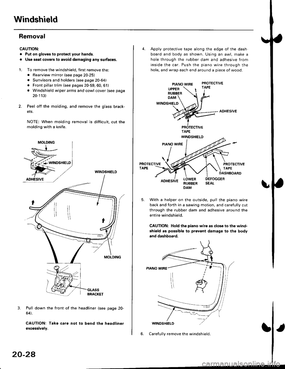
CAUTION:
. Put on gloves to plotest your h8nds.
. Use seat covers to avoid damaging any surfaces.
1. To remove the windshield, first remove the:. Rearview mirror (see page 20-25)
. Sunvisors and holders (see page 20-64)
. Front pillar trim (see pages 20-59, 60, 61)
! Windshield wiper arms and cowl cover (see page
20-1131
Peel off the molding, and remove the glass brack-
ers.
NOTE: When molding removal is difficult, cut the
molding with a knife.
WINDSHIELO
3. Pull down the front of the headliner (see page 20-
64).
CAUTION: Take care not to bend the headlinet
excsssively.
MOLDING
20-24
4. Apply protective tape along the edge of the dash
board and body as shown. Using an awl, make a
hole through the rubber dam and adhesive from
inside the car. Push the piano wire through the
hole, and wrap each end around a piece of wood-
PIANO WIREPROTECTIVE
UPPERRUBBER| '1"
DAM
WINDSHIELO
AOHESIVE
RUBBERDAM
With a helper on the outside, pull the piano wire
back and forth in a sawing motion, and carefully cut
through the rubber dam and adhesive around the
entire windshield.
CAUTION: Hold the piano wile as close to ihe wind-
shield as possible to prevent damage to the body
and dashboard.
WINDSHIELD
6. Carefully remove the windshield.