Page 1052 of 2189
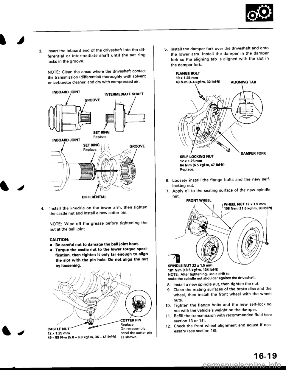
3. lnsert the inboard end of the driveshaft into the dif-
terential or intermediate shaft until the set ring
locks in the groove
NOTE: Clean the areas where the driveshaft contact
the transmission (differential) thoroughly with solvent
or carburetor cleaner, and dry with compressed air'
INBOARD JOINT
INBOARD JOINTReplace.
GROOVE
an
DIFFERENTIAL
lnstall the knuckie on the lower arm. then trghten
the castle nut and install a new cotter pin
NOTE: wipe off the grease before tightening the
nut at the ball ioint.
CAUTION:
. Be careful not to damago the ball ioint boot'
. Torque the castle nut to the lower torque sp€ci-
fication, thsn tighten it only far enough to align
the slot with th€ pin hol6. Do not align the nut
by loosening.
CASTLE NUT12 x 1 .25 mm
COTTER PINReplace.On reassemblY,bend the cotter pinJi$ - 59 N.m 15.0 - 6.0 kgl m,35 - 43 lbf ftl
16-19
5. lnstall the damper tork over the driveshaft and onto
the lower arm. Install the damper in the damper
fork so the aligning tab is aligned with the slot in
the damPer fork.
FLANGE BOLTl0 r 1.25 mmrit N.m t4.a kgf.m, 32 lbf.ft) AIIGN|NG TAB
1.
SELF-LOGKING NUT12 x 1.25 mm6,1N.m 16.5 kgi.m, a7 lbfftl
Replace.
Loosely install the flange bolts and the new self-
locking nut.
Apply oil to the seating surface of the new spindle
nut.
181 N m 118.5 kgt'm, 13il lbt'ftl
NOTE: Aftortightening, use a drift to
stake the spindle nut shoulder against the drivoshaft'
8. Install a new spindle nut, then tighten the nut'
9. Clean the mating surfaces ot the brake disc and the
wheel. then install the front wheel with the wheel
nuts.
10. Tighten the flange bolts and the new self-locking
nut with the vehicle's weight on the damper.
11. Refill the transmission with recommended fluid (see
section 13 or 14).'t2. Check the front wheel alignment and adjust if nec-
essary (see section 18),
FRONT WHEEL
SPINDLE NUT 22 x 1.5 mm
WHEEL NUT 12 x 1.5 mm108 N.m (11.0 kgl'm, g) lbl ftl
Page 1058 of 2189
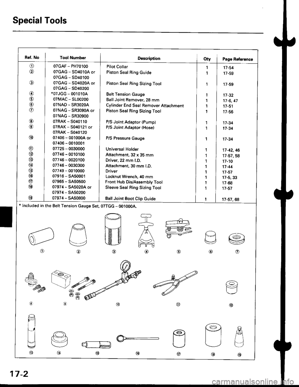
Ref. No I Tool NumberDescriptionOty I Pag€ Reterence
o
@
@
@
@
fof
@
@
@
@
@
@
@
@
@
@
@
@
@
07GAF - PH70100
07GAG - SD4010A or
07GAG - SD40100
07GAG - SD4020A or
07GAG - S040200*07JGG - 00r 010A
07MAC - 5100200
OTNAD - SR3O2OA
07NAG - SR3090A or
07NAG - SR30900
07RAK - 5040110
07RAK - 5040121 or
07RAK - 5040t20
07406 - 0010004 or
07406 - 001000r
07725 - 0030000
07746 - 0010100
07746 - 0020100
07746 - 0030300
07749 - 0010000
07916 - SA50001
07965 - SA50500
07974 - SA5020A or
07974 - SA50200
07974 - SA50800
Pilot Collar
Piston Seal Ring Guide
Piston Seal Ring Sizing Tool
Belt Tension Gauge
Ball Joint Remover, 28 mm
Cylinder End Seal Bemover Attachment
Piston Seal Ring Sizing Tool
P/S Joint Adaptor (Pump)
P/S Joint Adaptor (Hose)
P/S Pressure Gauge
Universal Holder
Attachment,32 x 35 mm
Driver, 22 mm l.D.
Attachment, 30 mm l.D.
Driver
Locknut Wrench, 40 mm
Front Hub DiVAssembly Tool
Sleeve Seal Ring Sizing Tool
Bsll Joint Boot Clip Guide
1
1
'I
1'I
1
I
1
1
I
1
1
I
1
1
I
1
I
11-54
17-59
'17-59
17 -32
17 -6, 47
17-51
| /-ao
17 -34
17 -31
't7 -34
't7-42, 16
17-57,58
17-10
17-44't7 -57
17-5,33
17-68
17 -57
17-57, 6A* lncluded in the Belt Tension cauge Set, 07TGG - OO10OOA.
o
p
v
@o
€_
ts7-dysB
aal
@@
(o)
F=1
@@@
@@@
17-2
Page 1060 of 2189
Inspection and Adjustment
Steering Operation
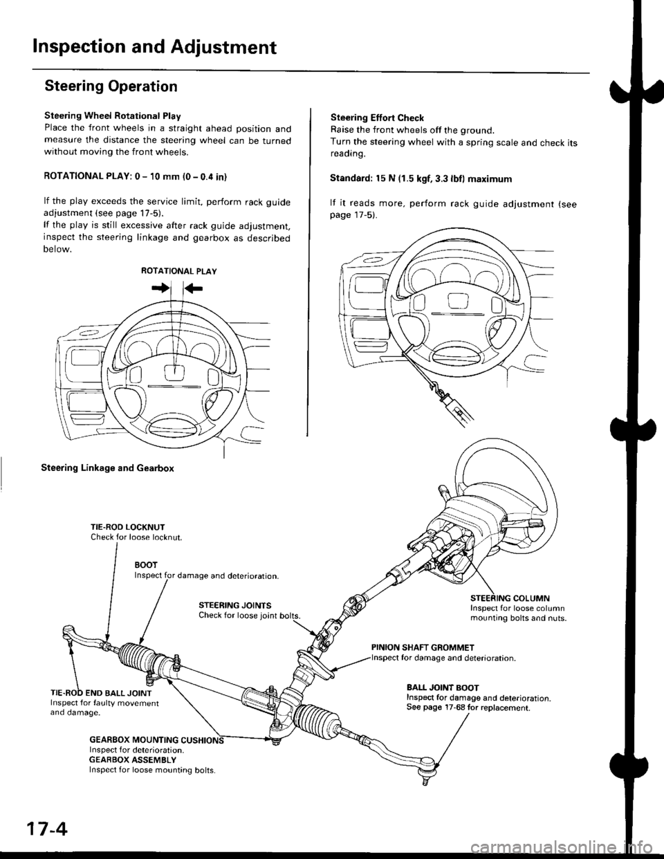
Steering Wheel Rotational Play
Place the front wheels in a straight ahead position andmeasure the distance the steering wheel can be turnedwithout moving the front wheels.
ROTATIONAL PLAY: 0 - 10 mm (0 - 0.4 in)
lf the play exceeds the service limit, perform rack guide
adjustment (see page lT-5).
lf the play is still excessive after rack guide adjustment,inspect the steering linkage and gearbox as descrjbed
Detow.
Steering Linkage and Gearbox
TIE.ROO LOCKNUTCheck for loose locknut.
BOOTInspect for damage and deterioration.
STEERING JOINTSCheck for loose joint
END BALL JOINTInspect for faulty movementano oamage.
GEABBOX MOUNTINGInspect f or deterioration.GEABBOX ASSEMBLY
Ste€ring Effort Check
Raise the front wheels off the ground.
Turn the steering wheel with a spring scale and check itsreaorng,
Standard: 15 N (1.5 kgf, 3.3 lbll maximum
lf it reads more. perform rack guide adjustment (see
page 17-5).
COLUMNInspect for loose columnmounting bolts and nuts.
PINION SHAFT GROMMETfor damage and deterioration.
BALL JOINT BOOTInspect for damage and deterioration.See pago 17-68 tor replacement.
ao-\---------U
17-4
Inspect for loose mounting bolts.
Page 1069 of 2189
)
lnstallation
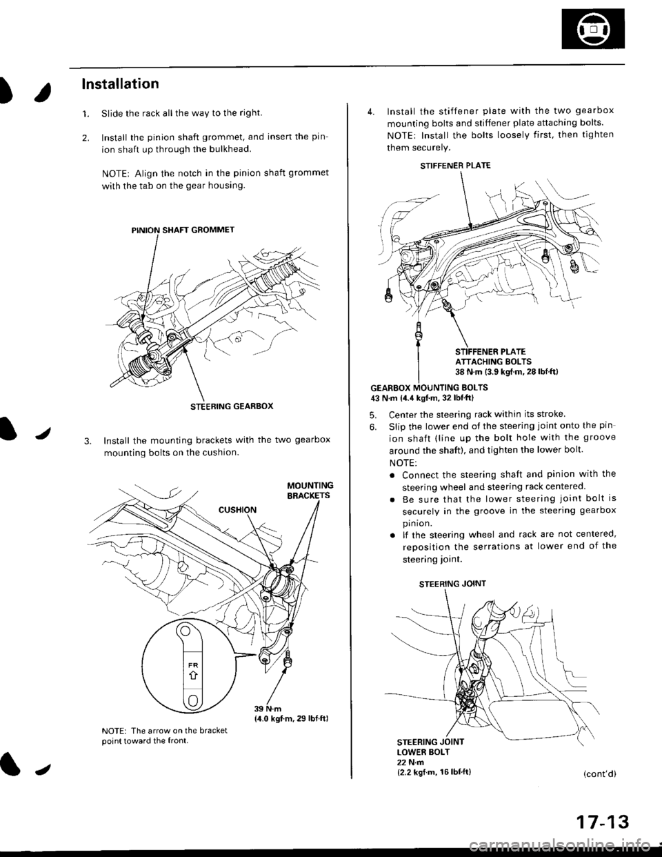
Slide the rack all the way to the righl
Install the pinion shaft grommet, and insert the pin
ion shaft up through the bulkhead.
NOTE| Align the notch in the pinion shaft grommet
with the tab on the gear housing.
1.
2.
J3. Install the mounting brackets with the two gearbox
mounting bolts on the cushion.
NOTE: The arrow on the bracketpoint toward the front.
STEEBING GEARBOX
{4.0 kgt.m,29 lbf.ftl
J
4. Install the stiffener plate with the two gearbox
mounting bolts and stiffener plate attaching bolts.
NOTEr Install the bolts loosely first. then tighten
them securely.
GEARBOX MOUNTING EOLTS43 N.m {4.4 kgf.m, 32 lbf'ftl
5. Center the steering rack within its stroke
6. Slip the lower end ot the steering joint onto the pin
ion shaft (line up the bolt hole with the groove
around the shaft), and tighten the lower bolt.
NOTE:
. Connect the steering shaft and pinion with the
steering wheel and steering rack centered
Be sure that the lower steering joint bolt is
securely in the groove in the steering gearbox
pin ion.
lf the steering wheel and rack are not centered,
reposition the serrations at lower end of the
steering ioint.
STEERING JOINT
STEERING JOINTLOWER BOLT22 N.m{2.2 kgf.m, 16lbf'ft}(cont'd)
I t- t5
STIFFENER PLATE
ATTACHING BOLTS38 N.m (3.9 kgf.m.28lbf.ftl
Page 1070 of 2189
Steering Gearbox
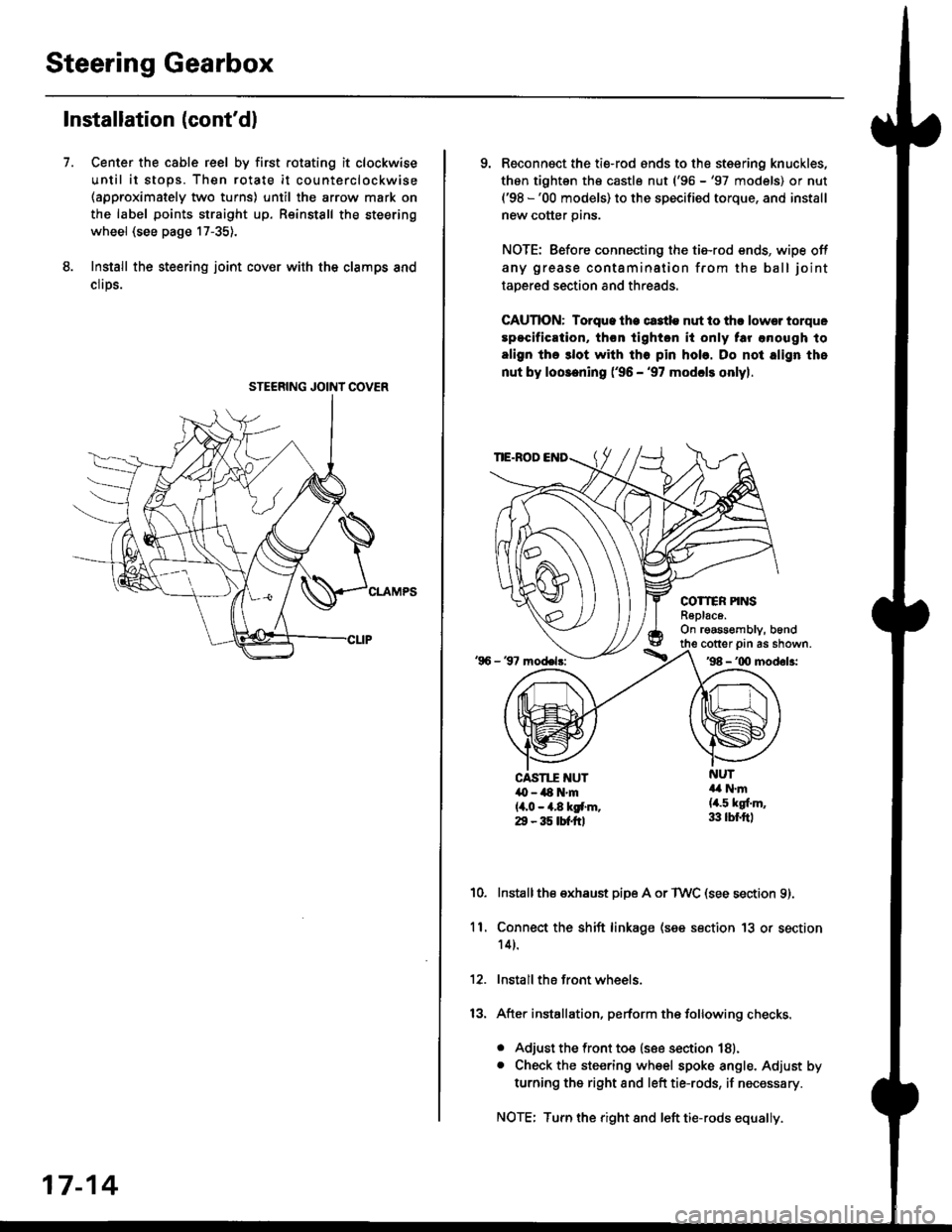
Installation (cont'dl
Center the cable reel by first rotating it clockwise
until it stops. Then rotate it counterclockwise(approximately two turns) until the arrow mark on
the label points straight up. Reinstall the steering
wheel (see page 17-35).
Install the steering joint cov€r with the clamps and
clrps.
7.
STEERING JOINI COVER
17-14
9. Reconnsct the ti€-rod ends to the steering knuckles,
thon tightsn th€ castle nut ('96 -'97 models) or nut('98 -'00 models) to the specified torque, and install
new cotter pins.
NOTE: Before connecting the tie-rod ends, wipe off
any grease contamination from the ball joint
tapered section and threads.
CAUTION: Torque lhe ct3tle nut to thr lowsr torque
spocification, th€n tighton it only tar anough to
align the 3lot with tho pin hob. Do not align the
nut by loosening ('96 - '97 modcls onlyl.
TIE.ROD
COTTER PINSR6plac6.On rgassombly, b6nd
'96 - 37 model3:
cotter prn as shown.'98 - '00 modol3:
NUT4a N.m(4.5 kgf.m,33 lbr.ftl
CAST1T NUT,O - ilt N'm{4,0 - 4.8 kgf.m.29 - 35 tbtftl
10.Installthe exhaust pipe A or TWC (see section 9).
Connect the shift linkage (see section 13 or section
14).
Install the front wheels.
After installation, perform the following checks.
. Adjust the front toe (see section 18).. Check the steering wheel spoke angle. Adjust by
turning the right and left tie-rods, if necessary.
NOTE: Turn the right and left tie-rods equally.
ll.
Page 1103 of 2189
Steering Gearbox
)
Removal
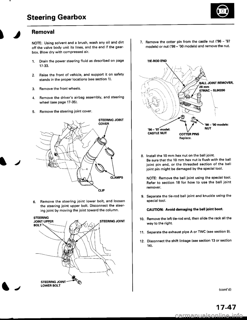
NOTE: Using solvent and a brush, wash any oil and dirt
off the valve body unit its lines. and the end if the gear-
box. Blow dry with comPressed air.
1. Drain the power steering fluid as described on page
2. Raise the front of vehicle, and support it on safety
stands in the proper locations (see section 11.
3, Remove the front wheels.
4. Remove the driver's airbag assembly, and steering
wheel (see page 17-35)
5. Bemove the steering joint cover.
6. Remove the steering joint lower bolt, and loosen
the steering joint upper bolt. Disconnect the steer-
ing joint by moving the ioint toward the column
tJ
17-47
TIE.ROD END
7. Remove the cotter pin from the castle nut {'96 -'97
models) or nut ('98 - '00 modslsl and remove the nut.
BALL JOINT REMOVER.28 mm07MAC - SLqI2|X)
'98 - '00 mod.b:NUT
8.
COTTER PINSRepl6ce.
lnstall the t0 mm hex nut on the ball joint.
Be sure that the 10 mm hex nut is flush with the ball
joint pin end, or the threaded section of the ball
joint pin might be damaged by the special tool.
NOTE: Remove the ball joint using the special tool.
Refer to section 18 for how to use ths ball joint
remover.
Seoarate the tie-rod ball joint and knuckle using the
specialtool.
CAUnON: Avoid damaging tho ball ioint boot.
Remove the left tie-rod end, then slide the rack all the
way to the right.
Separate the exhaust pipe A or TWC (see section 9).
Disconnect the shift linkage (see section 13 or section
14).
(cont'd)
9.
10.
11.
12.
Page 1121 of 2189
71.Connect the air tube between the right and left
boot.
lnstall the clips on the cylinder lines' then clamp the
air tube with the cliPs.
l./
CYLINDER LINE A
CLIP
l-,
lnstallation
CAUTION: Be carelul not to bend or damage the feed
line and cylinder lines when installing the gearbox'
1, Before installing the gearbox, slide the rack all the
way to right.
2. Install the mounting cushion on the steering gear-
DOX.
Install the pinion shaft grommet, then insert the pin-
ion shaft up through the bulkhead.
NOTE: Align the notch in the pinion shaft grommet
with the tab on the valve housing.
Install the mounting bracket over the mounttng
cushion, then installtwo gearbox mounting bolts'
MOUNTING BRACKET
cusHroN
39 N.m(4.0 kgj m, 29 lbtftlNOTE: Install the bracket
with the arrow Pornllngtoward the front.(cont'd)
17-65
Page 1123 of 2189
)
1?
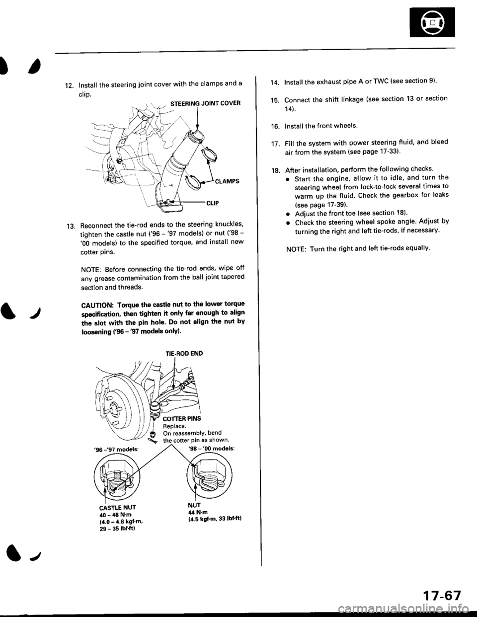
12, Install the steering joint cover with the clamps and a
clrp.
Reconnect the tie-rod ends to the steering knuckles,
tighten the castle nut ('96 -'97 models) or nut ('98 -
'OO models) to the specified torque, and install new
cotter plns.
NOTE: Before connecting the tie-rod ends, wipe off
any grease contamination from the ball joint tapered
section and threads.
CAUTION: Torquo the castle nut to the lower torque
sp€cification, then tighten it only tar enough to align
the slot with the pin hole. Do not align the nut by
loosening {,96 -'97 models only).
COTTER PINSReplace.On reassembly, bend
the cotter Pin 6s shown.'96 -'97 models:'98 -'00 mod€ls:
tr
CASTLE NUT40 - a8 N'm(4.0 - 4.8 kgf'm,29 - 35 lbf.ftl
NUT&l N.m{a.5 kgf'm, 33 lbl'ftl
NE-ROD END
(l-,
17-67
14.
15.
16.
17.
18.
Install the exhaust pipe A or TWC (see section 9).
Connect the shift linkage (see section 13 or section
14).
lnstall the front wheels
Fill the system with power steering fluid, and bleed
air from the system (see page 17-331
After installation, perform the following checks
. Start the engine, allow it to idle, and turn the
steering wheel from lock-tolock several times to
warm up the fluid. Check the gearbox for leaks
(see page 17-39).
. Adjust the front toe (see section 18).
. Check the steering wheel spoke angle. Adjust by
turning the right and left tie-rods, if necessary.
NOTE: Turn the right and left tie-rods equallv