Page 445 of 2189

PGM-FI System
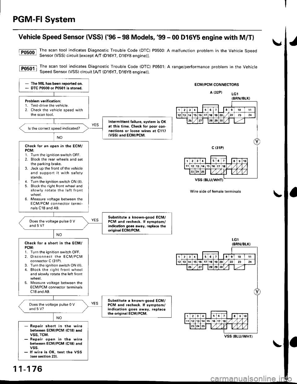
Vehicle Speed Sensor (VSSI ('96 - 98 Models,'99 - 00 D16Y5 engine with M/Tl
@The scan tool indicates Diagnostic Trouble Code (DTC) P0500: A malfunction problem in the Vehicle SpeedSensor (VSS) circuit Iexcept A!/T (D16Y7, D16Y8 engine)1.
The scan tool indicates Diagnostic Trouble Code (DTC) P0501: A range/performance problem in the VehicleSpeed Sensor (VSS) circuit [A,rT {D16Y7, D16Y8 engine)].
ECM/PCM CONNECTORS
A {32P} LG.t
VSS IBLU/WHT}
Wire side ot temale terminals
LGI(BRN/8LK}
The MIL has been reDorted on.DTC P0500 or P0501 is stored.
Problem verification:1- Test drive the vehicle.2. Check the vehicle speed withthe scan tool.
Intermittent tailure, system is OKat this time. Check tor Door con-nections or loose wires at C117{VSSland ECM/PCM.
ls the correct speed indicated?
Check for an open in the ECM/PCM:1. Turn the ignition switch OFF.2. Elock the rear wheels and setthe parking brake.3. Jack up the front of the vehicleand support it with safetystands.4. Turn the ignition switch ON (ll).
5. Block the right tront wheel andslowly rotate the left front
6, Measure voltage between theECM/PCM connector termi-nals C18 and A9.
Subslitute a known-good ECM/PCM and recheck. lf symptom/indic.tion goes away, replace theorisinal ECM/PCM.
Does the voltage pulse 0 Vand 5 V?
Check tor a short in ihe ECM/PCM:1. Turn the ignition switch OFF.2. Disco n n ect the ECM/PCMconnector C (31P).
3. Turn the ignition switch ON {ll).4. Block the right front wheeland slowly rotate the left front
5. Measure voltage between theECM/PCM connector terminalsC18 and A9.
Substitute a known-good ECM/PCM and recheck. lI symptom/indication goes away. replacethe original ECM/PCM.
Does the voltage pulse 0 Vand s V?
- Repair short in the wirebetwGen ECM/PCM {C18} endvss, TcM.- Repair open in the wirebetween ECM/PCM {Cl8} andvss.- lf wire is OK, test the VSSlsee section 23).
{BRN/BLK}
239l0lt
121611t8t9202321
2A2930
c {31P}
I38191o
tl12ialr5i6l10./
I2356a9l011
12l3l5t61tl8t920222a
27202930
12910
t2l13l.l7I l,/ 1,/231r.lslt., ),rlL
VSS {BLU/WHT}
11-176
Page 589 of 2189

. Torque the mounting bolt and nuts in the sequence
shown.
O 12 x 1.25 mm64 N.m {6.5 kgt.m,47 lbf.fr)
@ 12 x 1.25 mm74 N.m (7.5 kgl'm,54 tbt.fr)
Check that the bushings are not twisted or offset.
Install the clip as shown.
SHIFT ROD
Turn the boot so the hole is facing down.
Make sure the boot is installed on the shift rod.
O) 12 x 'l.25 mm64 N.m 16.5 kgl.m,47 tbt.ft)
I
a
a
a
a
8 x 1.25 mmN.m t2.2 kgt.m, l6 lbl'tt)
6 x 1.0 mm9.8 N.m (1.0 kgl.m.7.2 tbf.tr)
. Apply grease to the slave cylinder push rod.
NOTE: Use only Super High Temp Urea Grease
{P/N 08798 - 9002}.
CLUTCHUNE
a
a
(P/N-6tl
08798-9002)
8 x 1.25 mm22 N.m 12.2 kgl.n.16 tbf.frl
. Turn the breather cap so that the "F" mark points at
the front of the car as shown.
Refill the transmission with the recommended oil
(see page 13-3).
Connect the positive (+) cable first, then the negative
(-) cable to the battery.
Check the clutch oDeration,
Shift the transmission and check for smooth opera-
tion.
Check the front wheel alignment (see section 18).
FRONT
13-9
Page 630 of 2189
Transmission Assembly
Removal(cont'd)
14. Remove the driveshafts and the intermediate shaft(see section 16).
NOTE: Coat all precision the finished surfaces with
clean engine oil or grease. Tie plastic bags over the
driveshaft ends,
Remove the bolt, then disconnect the change elden-
sion.
Remove the clip and the spring pin, then disconnectthe change rod.
8x22mmSPRING PINCLIP Replace.
15.
13-50
17. Remove the front and the rear engine stiffensrs.
18. Remove the clutch cover.
CLUTCH COVER
6x1.0mm12 N.m (1.2 kg{.m,9 tbf.ftl
x 'l .25 mm
tJ
24 N.m {2.4 kgt m,17 rbt ftl
Page 682 of 2189

Description
(cont'dl
Gear Selection
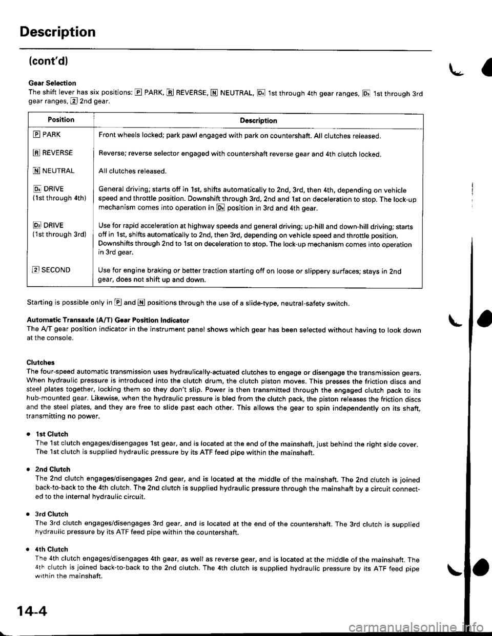
The shift lever has six positions: E PARK. E REVERSE, N NEUTRAL, E 1st through 4th gear ranges, E 1st through 3rdgear ranges, @ 2nd gear.
Starting is possible only in E and E positions through the use of a slide-type, neutral-safety switch.
Automatic Transaxle (A/f, Gear Position Indicator
The Ay'T gear position indicator in the instrument panel shows which gear has been selected without having to look downat the console.
Clutch€s
The four-speed automatic transmission uses hydraulically-actuated clutches to engage or disengage the transmission gears.When hydraulic pressure is introduced into the clutch drum, the clutch piston moves. This presses the friction discs andsteel plates together, locking them so they don't slip. Power is then transmitted through the engaged clutch pack to itshub-mounted gear. Likewise, when the hydraulic pressure is bled from the clutch pack, the piston releases the friction discsand the steel plates, and they are free to slide past each other. This allows the gear to spin independently on its shaft,transmitting no power.
lst Clutch
The 1st clutch engages/disengages 1st gear, and is located at the end of the mainshaft, just behind the right sroe cover.The 1st clutch is supplied hydraulic pressure by its ATF feed pipe within the mainshaft.
2nd Clulch
The 2nd clutch engagegdisengages 2nd gear, and is located at the middle of the mainshaft. The 2nd clutch is joined
back-to-back to the 4th clutch. The 2nd clutch is supplied hydraulic pressure through the mainshaft by a circutr connect-ed to the internal hvdraulic circuit,
3rd Clutch
The 3rd clutch engages/disengages 3rd gear, and is located at the end of the countershaft. The 3rd clutch is suooliedhydraulic pressure by its ATF feed pipe within the countershaft.
ilth Clutch
The 4th clutch engages/disengages 4th gear, as well as reverse gear, and is located at the middle of the mainshaft. The4th clutch is joined back-to-back to the 2nd clutch. The 4th clutch is supplied hydraulic pressure by its ATF feed pipewith in the mainshaft.
\-a
PositionDe3cription
E PARK
E REVERSE
N NEUTRAL
E DRIVE
{1st through 4th)
Ei DRtvE('lst through 3rd)
B SECOND
Front wheels locked; park pawl engaged with pa* on countershaft. All clutches released.
Reverse; reverse selector engaged with countershaft reverse gear and 4th clutch locked.
All clutches released.
General driving; starts off in 1st, shifts automatically to 2nd, 3rd, then 4th, depending on vehiclespeed and throttle position. Downshift through 3rd, 2nd and 1st on deceleration to stop. The lock-upmechanism comes into operation in @ position in 3rd and 4th gear.
Use for rapid acceleration at highway speeds and general driving; up-hill and down,hill dfiving; stansotf in 1st, shifts automatically to 2nd, then 3rd, depending on vehicle speed and throttle position.
Downshifts through 2nd to lst on deceleration to stop. The lock-up mechanism comes into operationin 3rd gear,
Use for engine braking or better traction starting off on loose or slippery surfaces; stays in 2ndgear, does not shift up and down.
14-4
Page 795 of 2189
Fluid Level
Ghecking
NOTE: Keep all foreign particles out of the transmis-
sron.
1.Warm up the engine to normal operating tempera-
ture (the radiator fan comes on)
Park the vehicle on the level ground, then turn off
the engrne.
Remove the dipstick (yellow loop) from the trans-
mission. and wipe it with a clean cloth.
Insert the dipstick into the transmrssron
Remove the dipstick and check the fluid level lt
should be between the upper mark and lower
marks.
UPPER MABKLOWER MARK
lf the level is below the lower mark, pour the recom-
mended fluid into the tiller hole to bring it to the
upper mark. Always use Genuine Honda Premium
Formula Automatic Transmission Fluid (ATF). Using
a non-Honda ATF can affect shift quality
K
L
DIPSTICK IYELLOW LOOPI
7. Insert the dipstick back into the transmission in the
direction shown.
FRONT
Installthe dipstick in the extent
of the direction shown.
14-117
Page 802 of 2189

Transmission
Removal(cont'd)
'10. Remove the cotter pins and castle nuts, th€n separatethe balljoints from the lower arms (see section 1gl.
DAMPER PINCH BOLT
NUT
FORI(FORK BOLT
11. Remove the right damper fork bolt. th€nright damper fork and dampor.
COTTER PINReplace.
separate
12.
1a
14.
Pry the right and left driveshafts out ofthe differential.
Pull on the inboard joint to remove the right and leftdrivsshafts (see section 16).
Tie plastic bags over the driveshaft onds.
NOTE: Coat all precision finished surfaces with cleanengine oil.
Remove the exhaust pipe A,
NOTE: Dl6YB engine is shown; D16y7 engine issimilar.
t9.
SELF-LOCKING NUTReplace.
L
14-124
EXHAUST PIPE AMOUNT/BRACKET
17.
18.
16. Remove the shift cable cover. then remove the shiftcable by removing the control lever,
CAUTION: Take car6 not to bond the shift cable.
Remove the right front mounvbracket.
Remove the ATF cooler hoses at the ATF coolerlines. Tufn the ends of the ATF cooler hoses uo toprevent ATF from flowing out, then plug the ATFcooler hosgs and lines.
NOTE: Check for any sign of leakage at the hoseioints.
WASHER
Page 862 of 2189

Transmission
Installation (cont'dl
9. Attach the torque converter to the drive plate witheight drive plate bolts and torque as follows:Rotate the crankshaft pulley as necessary to tightenthe bolts to 1/2 of the specified torque. then to thefinal torque, in a crisscross pattern.
After tightening the last bolt, check that the crank-shaft rotates freely.
TOROUE: 12 N.m {1.2 kgl.m, 8.7 tbt{r}
10 x 1.25 mm
6x1.0mm12 N.m (1.2 kgt m,8.7 rbt ft)
I 1.25 mm2/t N.m {2.4 kg{.m,17 tbt ftlCONVERTEB
10. Install the torque convener cover and the €nginestiffener.'11. Tighten the crsnkshaft pull€y bolt, if necessary (see
section 61.
12. Connect the ATF cooler hoses to the ATF cooler lines(see page 1,t192).
ATF COOIIRUNE
10 x 1.25 mma,l N.m {4.5 kgl.m,33 rbt.fttRIGHT FRONT 12 x 1.25 mmMOUNT/BRACKET 6.t N.m (6.5 kg{.m,47 tbt ftl
13. Install the right front mounvbracket.
4,r N.m 14.5 kgf.m,33 lbtft)
COVER
L,
14-1A4
SHIFT CABLE
SHIFT CAAE COVER
14. Install the control lever with a new lock washer tothe control shaft, then install the shift cable cover.
CAUION: Taks care not to bend the shift cable.
L(rcK WASHERReplace.
8 x 1,25 r'|m22N-m12.2 tgt m. 16lbnftl
x 1.0 mmtit N.m 11.4 kgt m,10 tbr,ft,
15. lnstall the exhaust pipe A.
NOTE: D16Y8 engine is shown; D16y/ engine is sim_ilar.
Replace.
GASKETReplace.
SELF.LOCKING NUTReplace.10 x 1.25 mm54 N.m (5.5 lgf.m,40 tbt ftl
NUTSELF.LOCKING NUTReplace.8 x 1.25 mm22 N.m {2.2 kgl.m, 16lbtfrl
Replace.8 x 1.25 mm16 N.m {1.6 kgI.m,12 tbf.ft)
Page 867 of 2189
Shift Cable
Removal/lnstallation
!@@ Make sure lifts are placed properly (see
seqtion 1).
1. Remove the front console (see section 20).
2. Shift to E position, then remove the lock pin Jrom
the adjuster.
SHIFT CABI.f
7 N.m(07kst'm,5lbl'ftl
3, Remove the shift cable bracket.
SHIFT CABLEBRACKET
6x1.0mm9.8 N.m{1.0 kgf m, 7.2
4. Remove the shift cable holder.
5. Bemove the shift cable cover.
6. Remove the control Iever from the control shaft,
then remove the shift cable. Take care not to bend
the cable when removing/installing it
I x '1.25 mm22 N.m12.2 kgl'm�.16 tbl.ftl
SHIFT CABLE HOLDER
SHIFT CABLE
LOCK WASHERReplace.
6x1.0mm12 N.m('1.2 ksf.m,8.7 rbtftl
CONTBOL LEVER6 x 'l.0 mm14 N.m
7.
(!.il kgt.m. 10lbl.ftl
lnstall the shift cable in the reverse order of removal'
Check the cable adjustment on reassembly (see
page 14-190).
14-189