1996 HONDA CIVIC Engine coolant lines
[x] Cancel search: Engine coolant linesPage 270 of 2189

!
Fuel and Emrsslons
SoecialToofs .....,...."..,. 11-2
Component Locations
lndex ....................., ......... 11-3
Svstem Description
Vacuum Connections ................,,..,.. ......... 11-12
Electrical Connections ...............,.,.,... ....... 11-29
System Connectors ........,.,.,.......................... 1 1-51
Troubleshooting
Troubleshooting Procedures ................. .. 11-81
Engine Control Module/PowertrainControl Module TerminalAfiangement ....,.,..... 11-88
Diagnostic Trouble Code Chart .................,., 11.97
How to Read Flowcharts .,.......................... . 11-103
PGM-Fl System
System Description ...... 11-10,1
Troubleshooting Flowcharts
Engine Control Module/PowertrainContlol Module ........ 11-107
Manitold Absolute Pressure Sensor .....'. . ... 11-115
fntake Air Temperatuie Sensor ..... . . ., . 11'121
Engine Coolant Temperatuae Sensol ........., 11-128
Throttle Position Sensor ...................,........... 11-132
Primary Heated Orygen Sensor (Sensor 1l ... 11-139
Secondary Heated Oxygen Sensor(Sensor 21.................................................... 1 1-153
Heated Oxygen Sensor Heater ...................,. 11-157
Fuel Supply System ...... 11-164
Random Mislire ......., ..11-166
Misfire Detected in One Cylindsr ................. 11-167
Knock Sensor .,.,............ 11-170
CKP/TDC/CYP Sensor ................................... 11'172
Vehicle Speed Sensor ...........,......,...,.,........... 1t-176
Barometric Pressure Sensor ...............,......... I 1-178
Electrical Load Detector,.,,............................ 1 1-179
CKF Sensor .................... 11-183
ECM/PCM Internal Circuit ............................. I 1-188
A/T Signal {TMA/TMBI .................................. I 1-189
ldle Control System
System Doscriplion ............ 11-190
Troubleshooting Flowcharts
ldle Control System ...... 11-192
ldle Air Control Va1ve .................................... I 1-19i1
Starter Switch Signal .................................... 1 1'202
Air Conditioning Signal ................................. 11'201
Ahernator FR Signal .................................... . 1 1-208
BrakeSwitch Signal ..................................... f 1"210
Power Sleering Prossure Switch Signal ......11-212
A/T Gear Position Signal ............................... 11-216
Clutch Swiich Signal ................................-.... 11-214
ldte Speed Setting . .............11-220
Fuel Supply System
Fuel Lines .,...................,.,.,.,11-221
Fuef Tube/Ouick-Connect Fittings ..........,.,........ 11 -227
System Description ....'.... 11-230
Fuel Pressure .......,.,,........... 11-230
Fuef fniectors ......................11-232
Fu€f Pressure Regulator .....,.......................'...,. 11-231
Fuef Fifter ............................11-235
Fuel Pump .............'.......'.... 11-236
PGM-FI Main Relay .............11'237
Fuel Tank ................ ....,...'.'.' 11'211
Intake Air System
System Description ....-.-.....11-243
Air Cfeaner ...........,......."". .11-211
Throttle Cable .....................11-211
Throttfe Body ........ ..'... . . .,.11-211
Fuel Iniestion Air Control System ,.,.,....-........... 11-250
Emission Control System
System Description .-..........11-252
Taifpip€ Emission ...............11-252
Three Way Catafytic Convert€r ............,.,,.,.,.,.... 11 -252
Exhaust Gas Racirculaiion System ...,.,,,,.,.,.,.,,. 11'254
Positive Crankcas€ Ventilation System .... . . .. 11-266
Evaoorative Emission Controls ..................,,..,.,. 11 -267
Page 361 of 2189

Troubleshooting
Engine/P_o,wertrain Control Module Terminal Arrangement('99 - 00 Models except Dl6Y5 engine with M/Tl
ECM/PCM CONNECTOR A (32P)Wire side ot temale terminalsNOTE:Standard battery voltage is l2 V
ECM/PCM CONNECTOR A I32PI
Sign!l
3BLU2WSS (EVAP 8YPAsS SOLENOIDDrives EVAP bypass solenoid vatve,With gn'tion swnch ON (lll banery votlage
LT GRN/I/VIITVSV {EVAP CONTNOL CANISTERVENTSHUTVALVE]Drives EVAP controt ca n isrer v€nt shutWilh ignilion switch ON {tl): b€ttery vottage
8LU/GNNC8S (CRUISE CONTSOL SIGOown shift signal inpot lrom c.uise conrrolWhen crurss control is used:purses
68ED/YELPCS {EVAP PURGE CONTROLSOTENOIOVALVE)Drives EVAP purge conrrol sotenoid vatve.With engine running, engine cootant, betow r54.F (6a,C):
With engine.unning, €ngine coolant, abov€ 154.F(68'C): duty conlrolled
YELATPD {AT GEAR POSITIONSWITCH)ootects A/T gear posnion swilch s,gnar.In otherthan @ posilion: Apprcx. 5 V
8BLK,IflHTSO2SHTC (SECONDARY HEATED OXYGEN SENSOS HEATEFCONTFOL)
Drives sscondary h€ared oxygen senso.Wilh isn,rion swirch ON (ll):banery votraseWith lully warm6d dp€ngire runn'ng:dury controled
LT GRNATPNP (AT GEAF POSITIONSWITCH)oereds A/T 9€a r position switch signat.In Parr or neulrsl:0 VIn anyother position approx.5 v
t088NSCS (SERVICE CHECK SIGNAL)Oetects ssruice check connecror signal(the signalcausing a OTC indication)with rh€ t6rminal connected: 0 vWith the rerm ina I disconneded: abour 5 V of ban€ry
GNN/BIKD4IND (D4INDICATON]Drives Oa indicaio. lighr.With D4 indicator lightturned ON: O VWith D4 indicator lightturned OFF: battery vo ttageG8N/YETFTF (FUEL PUI\,4P SELAY)Orivos tuel pump relay,0V for two s€conds lfrer turnrng rgnilior swtcn ON(ll), then batt€ry voltage11BTI(REDACC (Al/C CTUTCH SELAY)Drives A./C clutch reray.With compressor ON:O VWilh comp.ssor OFF; battery vottage18GFN/OFNMI! (A,IAIFUNCTION INDICA.TOF LIGHT)With MlLturned ON:0 VWith l\,llL tornod OFF|batrery votrsge198tuNEP (ENGINE SPEED PUTSEIOulputs6ngine speed pulse,Wilh engin6.unning: putses
20GFNFANC {SADIATOR FAN CONTnoL)Orives radiarortan relay.Wirh r.distor t6n running:OVWith radiatortan stopped: banery vottage21ELUA/ELK LINESends and r€ceives s.an lool signal.With ignition switch ON (ll):p!ts€s
22'lBLUATP L {AT GEAS POSITIONswtTcH)Oelocis A"/T gear posirion switch siSnat.In othfflhan E position: Apprcx. 5 V
23SHO25 (SECONOARY HEATEDOXYCEN SENSOR, SENSOF 2)Detects secondsry hoar€d oxygen sensorWith lhronle f! lly or'6ned from idte with fu ywarmod up engine: above 0.6 vWiih th.onl6 quickb, closd:below 0,4 V24STS ISTAFTEN SWITCH SIGDebcrs staner switch signat.Wirh srarterswitch ON (tttJ: batteryvottogeWith sraftsr cwirch OFF:0 V26GFNPSPSW iPlS PNESSURESWITCII SIGNAL)Derecrs PSP switch signat.Atidle with steoring wheolin srraightahead position: O VAt idl6with steering wheetal fult lock: barery vo ttags27BLU/REOACS (AJC SWITCH SIGNALJOer*ts ,ay'C swirch signat.Wiih ty'C switch ON;0VWilh Ay'C switch OFF|aboor 5VWHT/REDSLU iINTERLOCK CONTROIUNIT)Drivos interloct control unit.With ignltion switch ON (ll)and brake pedaldepresed: batlory volrage29LT GRNPTANK (FUEL TANK PFESSUEESENSOR)Oer6ds lu€l tank pr€ssura sonsor signat.Wilh ig.rrrd swirch ON rttr and fuetti
cap ooen6d.
30GRN/FEOEr (ELOIWith parking lighlsrurned on ar idteiaboui 2.5- 3.S VWirh low beam he€dlig hts turnqd on ai idts: aboul 1.52.5 V32GRN/'WHTAKSW (BFAKE SWITCH)Detets brak€ swrtch signEt,With brake pedal r6l€ased:0 VWhh brake pedaldepres*d: battery voltEse'1:A./T (D16Y7, D16Y8 engine)*2: rvt/T13: CVT (D16Y5 engine)
11-92
Page 400 of 2189

PGM-FI System
t
I
Engine Coolant Temperature (ECT) Sensor
('99 - 00 Models except Dl6Y5 engine with M/Tl
The scan tool indicates Diagnostic Trouble Code (DTC) P0118: A high voltage (low temperature) problem in the
Engine Coolant Temperature (ECT) sensor circuit.
ECT SENSOR 2P CONNECTOR {C122)
ECT(RED/Wr{T)
JUMPER IVIRE
sG2{GRN/BLK)
wire side of female terminals
ECM/PCM CONNECTOB C 131PI
The MIL has been reported on,
oTC P0118 is stored.
Problem verilication:1. Turn the ignition switch ON (ll).
2. Check the ECT with the scan
tool.
lntormittent failuro, systom is OK
at thb timo. Check lor poor con'nections or 10036 wiraa at C122
{ECT ssnsorl and ECM/rcM.
ls -4'F (-20"C) or less lor L-Limit
in Honda mode o{ PGM Tester) or
5 V indicated?
Check for an open in the Efi sen'
sori1. Disconnect the ECT sensor 2P
connector,2. Connect the ECT sensor 2P
connector terminals No, 1 andNo. 2 with a jumper wire.3. Check the ECT with the scantool.
ls -4"F 1-20"C) or less (or L-Limit
in Honda mode of PGM Tester) or
5 V indicated?
Check for sn open in the wires
IECT. SG2 linesl:1. Turn the ignition switch OFF.2. Connect ECM/PCM connectorterminals C18 and C26 with ajumper wire.3. Turn the ignition switch ON (ll).
4. Check the ECT with lhe scantooi.
Rspair opon in th6 wiros bstwoon
ECM/PCM (Cl8, C26l and ECT
3ensot.
ls -4'F {-20"C) or less (or L-Limit
in Honda mode of PGN4 Tester) or
5 V indicated?
Substitute 6 known-good ECM/PCM and recheck. l{ no.mal EcT
is indicatod, .eplace the originalECM/PCM.
JUMPER WIRE
Wire side of female terminals
11-131
Page 520 of 2189

\J
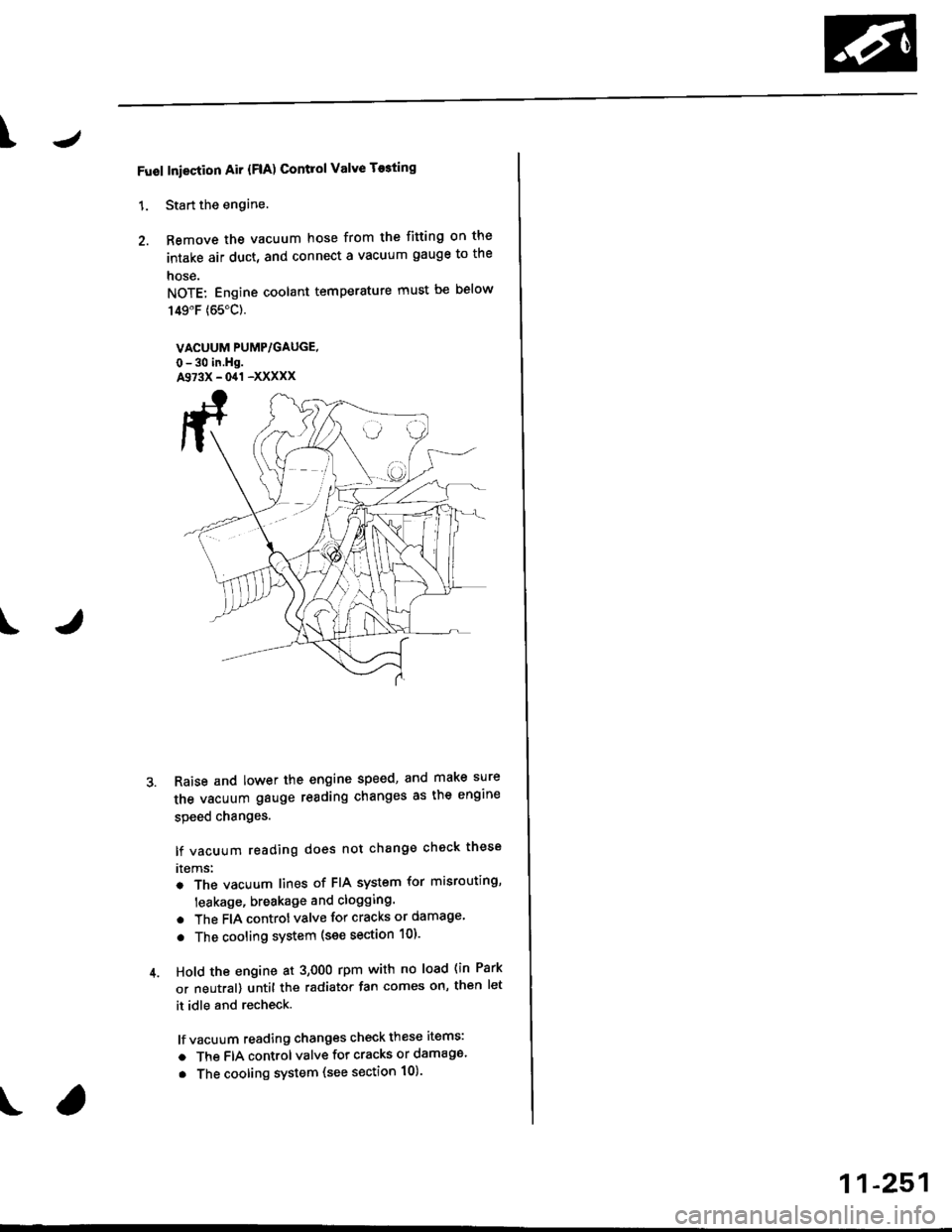
Fuol Iniection Air {FlA) Contlol Valve T$ting
1. Start the engine.
2. Remove the vacuum hose from the fitting on the
intake air duct, and connect a vacuum gauge to the
nose.
NOTE: Engine coolant temperature must be below
149"F (65"C).
VACUUM PUMP/GAUGE,
0-30 in.Hg.A973X - 041 -XXXXX
Raise and lower the engine speed, and make sure
the vacuum gauge reading changes as the engine
speed changes.
lf vacuum reading does not change check these
rtems:
. The vacuum lines of FIA system for misrouting,
leakage, breakage and clogging.
. The FIA controt valve for cracks or damage
. The cooling system (see section 10).
Hold the engine at 3,OOO rpm with no load (in Park
or neutral) until the radiator fan comes on, th€n let
it idle and recheck.
lf vacuum reading changes check these items:
a The FIA control valve for cracks or damage.
. The cooling system (see section 10).
11-251
Page 1380 of 2189

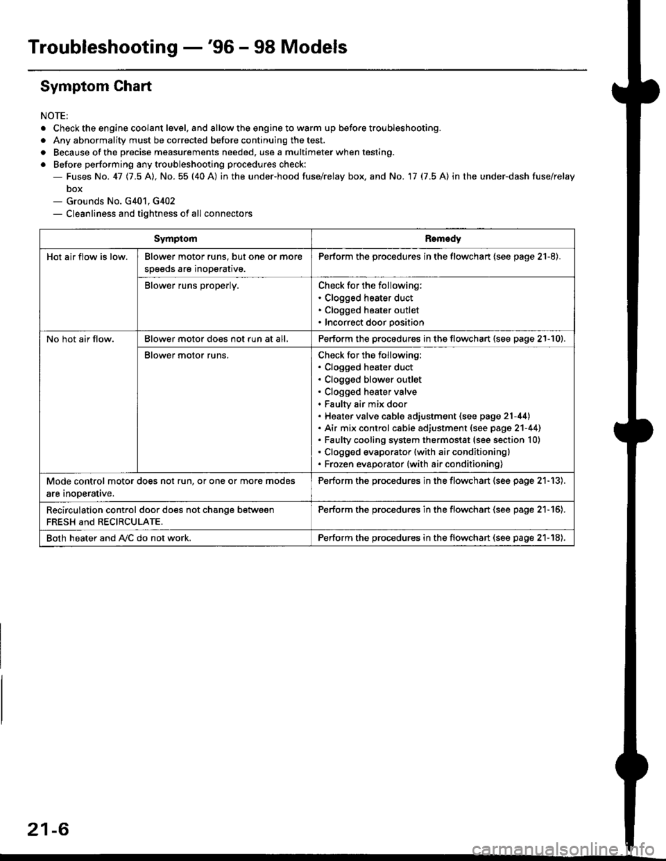
Troubleshooting -'96 - 98 Models
Symptom Chart
NOTE;
. Check the engine coolant level. and allow the engine to warm up before troubleshooting.
. Any abnormality must be corrected before continuing the test.
. Because of the precise measurements needed. use a multimeter when testing.
o Before performing any troubleshooting procedures check:- Fuses No. 41 11.5 Al, No. 55 (40 A) in the under-hood fuse/relay box. and No. 17 (7.5 A) in the under-dash fuse/relay
box- Grounds No. G401, G402- Cleanliness and tightness of all connectors
SymptomRomedy
Hot air flow is low.Blower motor runs. but one or more
speeds are inoperative.
Perform the procedures in the flowchart (see page 21-8).
Blower runs properly.Check for the following:. Clogged heater duct. Clogged heater outlet. Incorrect door position
No hot air flow.Blower motor does not run at all,Perform the procedures in the flowchart (see page 21-10).
Blower motor runs.Check for the following:. Clogged heater duct. Clogged blower outlet. Clogged heater valve. Faultv air mix door. Heater valve cable adjustment (see page 21-44). Air mix control cable adiustment (see page 2'l-441. Faulty cooling system thermostat (see section 10). Clogged evaporator (with air conditioning). Frozen evaporator {with air conditioning)
Mode control motor does not run, or one or more modes
are inooerative.
Perform the procedures in the flowchart (see page 21-13).
Recirculation control door does not chanqe between
FRESH and RECIRCULATE.
Perform the procedu.es in the flowchan (see page 21-16).
Both heater and A,/C do not work.Perform the procedures in the flowchart (see page 21-18),
21-6
Page 1393 of 2189

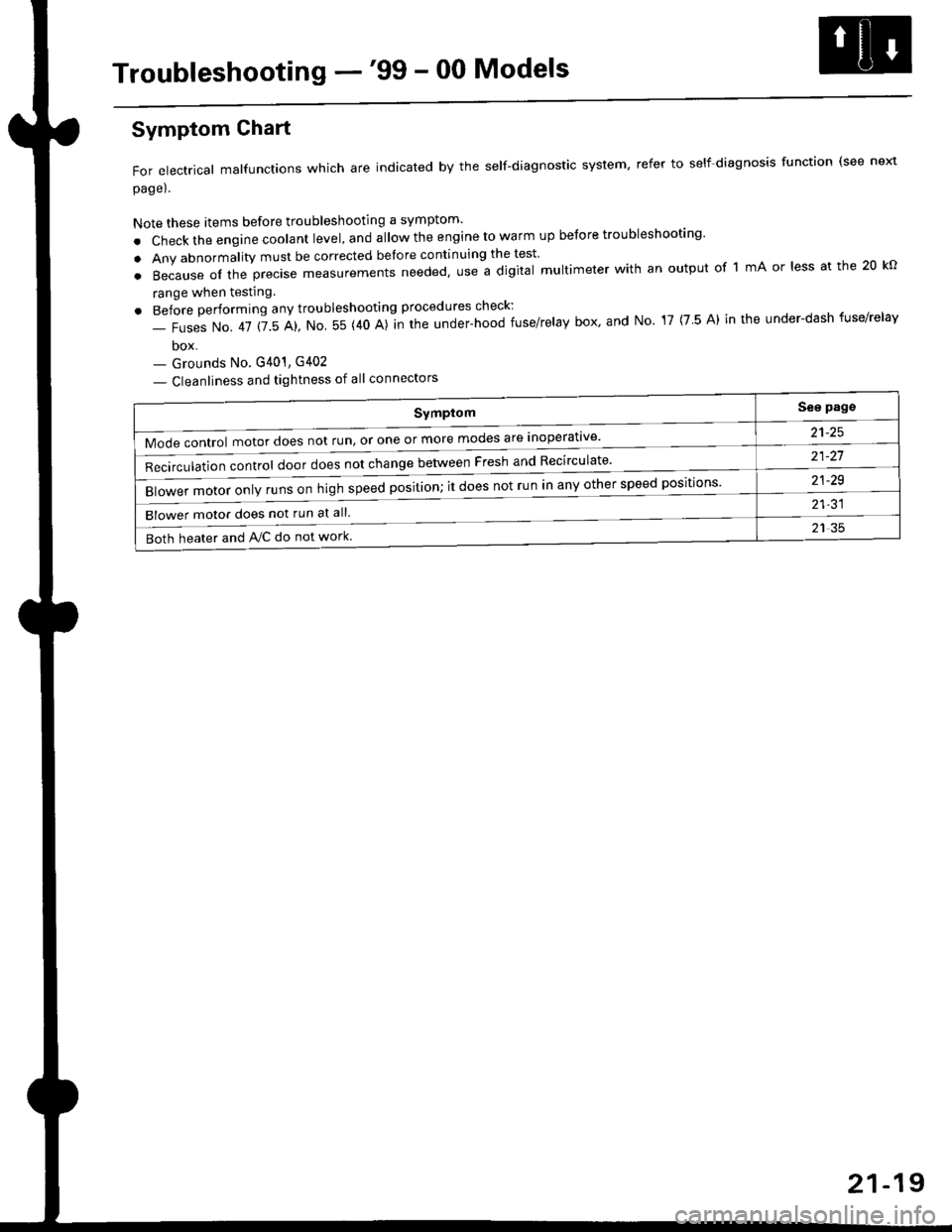
Troubleshooting -'99 - 00 Models
Symptom
Mode control motor does not run, or one or more modes are inoperat've'
Recirculation control door does not change between Fresh and Recirculate'
Blower motor only runs on high speed position; it does not run in any other speed positions
Blower motor does not run at all.
Both heater and Ay'C do not work
See pags
a1_tq
21-21
21-29
21-31
21 35
Symptom Chart
For electrical malfunctions which are indicated by the self-diagnostic system, refer to self-diagnosis function (see next
page).
Note these items before troubleshooting a symptom'
. Check the engine coolant level, and allow the engine to warm up before troubleshooting'
. Any abnormality must be corrected before continuing the test
.Becauseoftheprec|semeasurementsneeded,UseadigitaImu|timeterwithanoutputoflmAor|essatthe20ko
range when testing
. Before performing any troubleshooting procedures check:
- Fuses No. 41 115 Al, No 55 (40 A)]n the under-hood fuse/relay box' and No 17 (7 5 A) in the under-dash fuse/relav
box- Grounds No. G401, G402
- Cleanliness and tightness of all connectors
21-19
Page 1413 of 2189

Heater Unit
Replacement
SRS components are located in this area. Review the
SRS component locations, precautions, and procedures
in the SRS section {24} before performing repairs or ser-
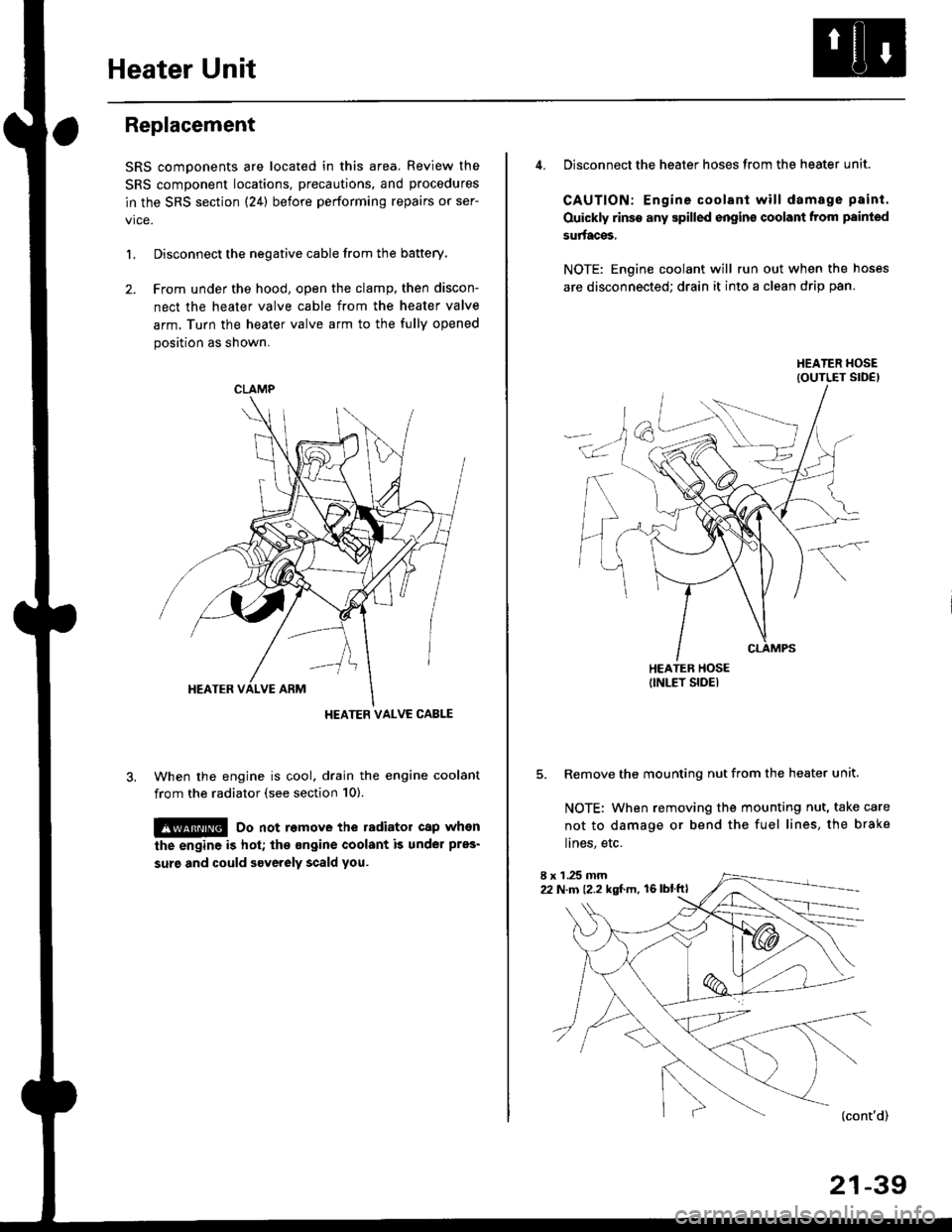
L Disconnect the negative cable from the battery.
2. Frcm under the hood, open the clamp, then discon-
nect the heater valve cable from the heater valve
arm. Turn the heater valve arm to the fully opened
position as shown.
When the engine is cool. drain the engine coolant
from the radiator (see section 10).
!@ Do not remove the radiator cap when
the engine is hot; the ongine coolant is under pres'
surg and could severely scald you.
CLAMP
HEATER VALVC CABLE
4. Disconnect the heater hoses from the heater unit.
CAUTION: Engine coolant will damage p8int.
Ouickly rinse any spilled engins coolant from painted
su aces,
NOTE: Engine coolant will run out when the hoses
are disconnected; drain it into a clean drip pan.
5. Remove the mounting nut from the heater unit.
NOTE: When removing the mounting nut, take care
not to damage or bend the fuel lines, the brake
lines, etc.
I x 1 .25 mm22 N.m {2.2 kgl.m, 16lblftl
21-39