1996 HONDA CIVIC Inspect brake light switch
[x] Cancel search: Inspect brake light switchPage 479 of 2189

ldle Control System
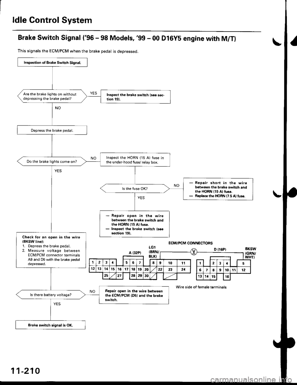
Brake Switch Signal ('96 - 98 Models, '99 - 00 Dl6YS engine with M/Tl
This signals the ECM/PCM when the brake pedal is deoressed.
LGlBKSW(GRN/WHTI
D {16P)
Wire side of female t€rminals
Inspection of Brake Switch Signal.
Are the brake lights on withoutdepressing the brake pedal?
Depress the brake pedal.
Inspect the HORN (15 A) fuse inthe under-hood fuse/ relay box.Do the brake lights come on?
- Repair short in the wirebetween the brake 3whch andrhe HORN 115 At lu3e.- Replace the I|oRN 17.5 A) tus€.
Repair open in the wirebetween the brake switch andthe HORN 115 Al fuse.Inspect th6 br.ke switch {s6€section l9l.Check tor an open in the wireIBKSW line):1. Oepress the brake pedal.2. Measure voltage betweenECM/PCNI connector terminalsAg and D5 with the brake pedaloepresseo.
Repair open in the wire b€tweenthe ECM/PCM {Dsl and the brakeswitch.
ls there battery voltage?
Brakc switch sign.l is OK.
ECM/PCM CONNECTOFS
A (32PtIBRI\v
,la678101112I
121311151617t8192022232aI9101112
25212Aa3013141516
11-210
Page 480 of 2189

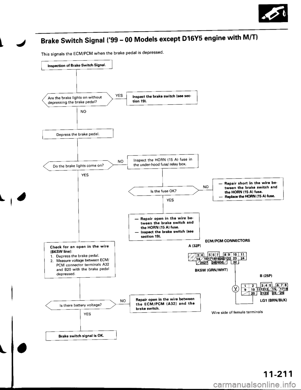
IJBrake Switch Signal ('99 - 00 Models except Dl6Y5 engine with M/Tl
This signals the ECM/PCM when the brake pedal is depressed
I
lnsoection ot Brake Switch signal.
Are the brake lights on without
depressing the brake Pedal?
Depress the brake Pedal
Inspect the HoRN {15 A} fuse in
the underhood fuse/ relay box'Do the brake lights come on?
- R.pair short in the wiro be'
tween the brake switch and
the HORN (15 Alfuse.- Replac€ the HORN (15 A) tuse.
- Repair open in the wite be'
tween the brako switch and
the HORN (15 Alfuse.- lnsoect the brake switch (3ec
section tgl.
Check fot an oPen in the wire
{BKsw linel:
1. Depress the brake Pedal.2. Measure vohage beween ECM/
PCM connector terminals A32
and 820 with the brake Pedaldepressed.
Bepair open in the wire between
the ECM/PCM (A32) and the
brake switch.
Brake switch signal i5 OK
ECM/PCM CONNECTORS
BKSW (GRN/WHTI
LG1 {BRN/BLK)
Wire side o{ female terminals
Page 489 of 2189

ldle Control System
ldle Speed Setting
Inspection/Adiustmenl
'96, '97 Dl6Y5. '96 - 00 Dl5Y8 sngine with M/T
NOTE:
. Before setting the idle speed, check the following
items:- The MIL has not been reported on.- lgnition timing- Spark plugs- Air cleaner- PCV system
o (Canada) Pull the parking brake lever up. Start the
engine, then check that the headlights are off.
1. Start the engine. Hold the engine at 3.000 rpm withno load (taansmission in neutral) until the radiatorfan comes on, then let it idle.
2. Connect a tachometer.
3. Disconnect the IAC valve connector.
4.lf the engine stalls, restart the engine with the accel-
erator pedal slightly depressed. Stabilize the rpm at1,000, then slowly release the pedal until the engineidles.
Check idling in no-load conditionsr headlights. blowerfan. rear defogger, radiator fan, and air conditioner
are not operating.
ldle spsed should be:
450 1 50 rpm
11-220
Adjust the idle speed, if necessary, by removing thecap and turning the idle adjusting screw.
NOTE; After adjusting the idle speed in this step,recheck the ignition timing (see section 23).
lf it is out of spec, go back to step 4.
IDLE
6. Turn the ignition switch OFF.
7. Reconnect the 2P connector on the IAC valve, then
do the ECM reset procedure.
8. Restart and idle the engine with no-load conditionsfor one minute, then check the idle speed.
NOTE: (Canada) Pull the parking brake lever up.Start the engine, then check that the headlights areoff.
ldle sp€sd should b€:
670 i 50 rpm IUSA)750 t 50 rpm {Canada}
9. ldle the engine tor one minute with headlights {Low)ON. and check the idle speed.
ldle speed should be:
750 :r 50 rpm
10. Turn the headlights off. ldle the engine for oneminute with heater fan switch at Hl and air conditioneron, then check the idle speed.
ldle speed should be:
810150 rpm
NOTE: lf the idle speed is not within specification,see Symptom Chan on page 11-84.
Page 731 of 2189

SYmPtom
E indicator light does not come on tor two seconds after ignition
switch is first turned ON {ll}.
E indicator light is on constantly (not blinking) whenever the ignition
switch is ON (ll).
Shift lever cannot be moved from @ position with the brake pedal
depressed.
Inspection Ref. Page
11-16
14-78
Inspection't4-79
lf the self-diagnostic l-d indicator light does not blink, perform an inspection according to the table below.
NOTE: lf a customer describes the symptom for code Pl706 {6), it will be necessary to recreate the symptom by test-driv-
ing, then recheck the DTC.
14-53
Page 733 of 2189

E i"dl.r." fiSh, 1."""". y{*fu
Reference page
14- 101
lE indicator light does not come on for two seconds after ignition switch is first turned oN (ll).14-102
Shift lever cannot be moved from E position with the brake pedal deprsssed'14-104
lf the self-diagnostic E indicator light does not blink and following symptoms appear, perform an inspection according to
the table below.
14-55
Page 1159 of 2189

)
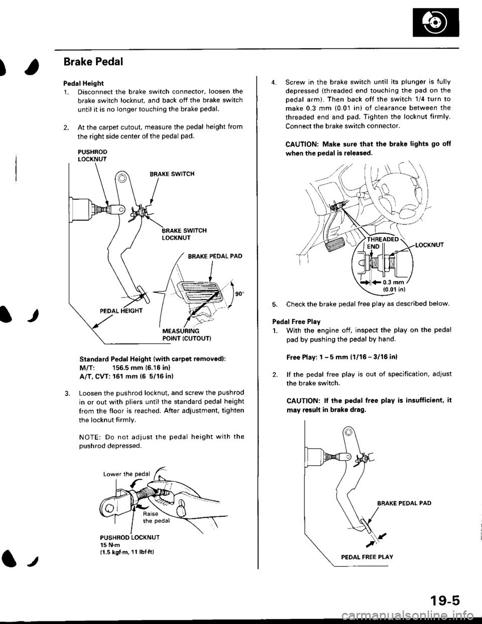
Brake Pedal
Pedal Height
1. Disconnect the brake switch connector, loosen the
brake switch locknut, and back off the brake switch
until it is no longer touching the brake pedal,
2. At the carpet cutout, measure the pedal height from
the right side center of the pedal pad.
PUSHRODLOCKNUT
Standard Pedal Height (with carpet removed):
M/T: 156.5 mm 16.16 inl
A/T, CVT: 161 mm (5 5/16 in)
3. Loosen the pushrod locknut, and screw the pushrod
in or out with pliers until the standard pedal height
from the floor is reached. After adjustment, tighten
the locknut firmly.
NOTE: Do not adiust the pedal height with the
Dushrod depressed.
It
PUSHROO LOCKNUT15 N.m(1.5 kgf.m. 11 lbI.ft)
POINT ICUTOUTI
4. Screw in the brake switch until its plunger is fully
depressed (threaded end touching the pad on the
pedal arm). Then back off the switch 1/4 turn to
make 0.3 mm (0.01 in) of clearance between the
threaded end and pad. Tighten the locknut firmly.
Connect the brake switch connector.
CAUTION: Make sure that the brake lights go off
when the pedal is released.
LOCKNUT
5. Check the brake pedal free play as described below.
Pedal Free Plsy
1. With the engine off, inspect the play on the pedal
pad by pushing the pedal by hand.
Free Play: 1 - 5 mm (1/16 - 3/16 inl
2. lf the pedal free play is out of specitication, adjust
the brake switch.
CAUTION: lf the pedal free play is insufficient, it
may result in brake drag.
BRAKE PEDAL PAO
)
19-5
*0.3 mm(0.01 in)
Page 1636 of 2189

Lighting System
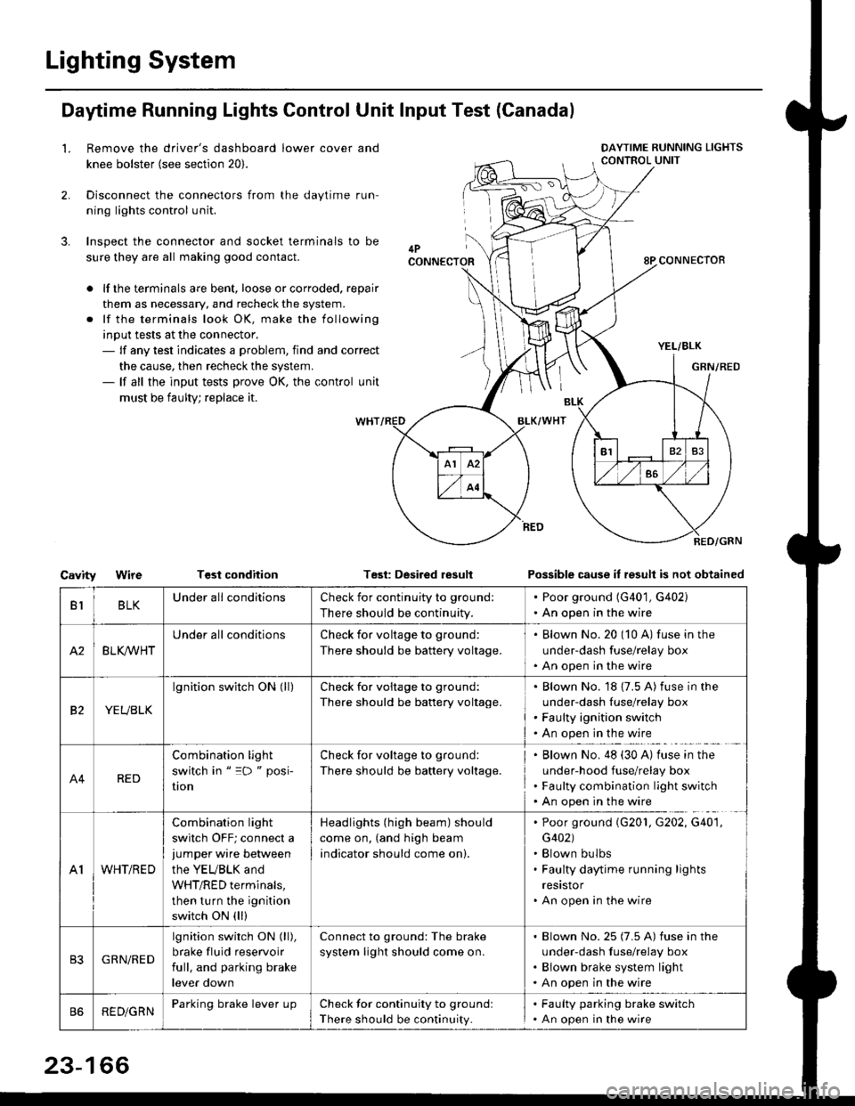
Daytime Running Lights Control Unit Input Test (Canadal
2.
3.
LRemove the driver's dashboard lower cover and
knee bolster (see section 20).
Disconnect the connectors from the daytime run-
ning lights control unit.
Inspect the connector and socket terminals to be
sure they are all making good contact.
lf the terminals are bent, loose or corroded. repair
them as necessary, and recheck the system.
lf the terminals look OK, make the following
input tests at the connector,- lf any test indicates a problem, find and correct
the cause, then recheck the system.- lf all the input tests prove OK, the control unit
must be faulty; replace it.
CavityWireTGst conditionTest: Desired resultPossible cause it result is not obtained
BLKU nderall conditionsCheck for continuity to g.ound:
There should be continuity.
. Poor ground (G401, G402). An open in the wire
A2BLK /VHT
Underall conditionsCheck for voltage to ground:
There should be battery voltage.
Blown No.20 (10 A) fuse in the
under-dash fuse/relay box
An open in the wire
etYEUBLK
lgnition switch ON (ll)Check for voitage to ground:
There should be battery voltage.
Blown No. 18 {7.5 A) fuse in the
under-dash luse/relay box
Faulty ignition switch
An open in the wire
A4RED
Combination light
switch in " =D " posi-
UOn
Check for voltage to ground:
There should be battery voltage.
Blown No. 48 (30 A) tuse in the
under-hood fuse/relay box
Faulty combination light switch
An open in the wire
A1WHT/RED
Combination light
switch OFF; connect ajumper wire between
the YEUBLK and
WHT/RED terminals,
then turn the ignition
switch ON (ll)
Headlights (high beam) should
come on, (and high beam
indicator should come on).
. Poor ground (G201, G202, G40'1,
G402). Blown bulbs. Faulty daytime running lights
resrstor. An open in the wire
GRN/RED
lgnition switch ON (ll),
brake fluid reservoir
full, and parking brake
lever down
Connect to ground: The brake
system light should come on.
Blown No.25 (7.5 A) fuse in the
under-dash f use/relay box
Blown brake system light
An open in the wire
REDiGRNParking brake lever LrpCheck for continuity to groundl
There should be continuity.
. Faulty parking brake switch. An open in the wire
23-166