Page 1141 of 2189

Front Damper
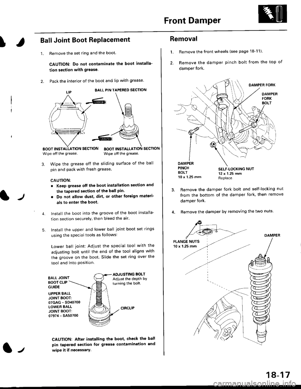
!Ball Joint Boot RePlacement
1.Remove the set ring and the boot.
CAUTION: Do not contaminate the boot installa-
tion section with grease.
Pack the interior of the boot and lip with grease
EALL PIN TAPERED SECTION
EOOT INSTALLATION SECTION
Wipe off the grease.BOOT INSTALLATION SECTION
Wipe off the grease.
lJ
3. Wipe the grease off the sliding surface of the ball
pin and pack with fresh grease.
CAUTION:
. Keep grease off the boot installation section and
the tapeled section of the ball pin.
5.
. Do not allow dust, dirt, or other toreign materi-
als to enter the boot.
Install the boot into the groove of the boot installa-
tion section securely, then bleed the atr.
Install the upper and lower ball joint boot set rings
using the special tools as follows:
Lower ball joint: Adiust the special tool with the
adjusting bolt until the end of the tool aligns with
the groove on the boot. Slide the set ring over the
tool and into Position.
BALL JOINTAOJUSTING BOLTAdjust the depth by
turning the bolt.BOOT CLIPGUIDE
4.
UPPER EALLJOINT EOOT:07GAG - SD40700LOWER BALLJOINT BOOT:07974 - SA50700
CAUTION: After installing the boot, check the ball
pin tapsrod section fol grease contamination and
wipe it if necessary.lt
18-17
Removal
l. Remove the front wheels (see page 18-11).
2, Remove the damper pinch bolt trom the top of
damper fork.
DAMPER FORK
OAMPERFORKBOLT
OAMPERPINCHAOLT10 x 1.25 mm
SELF-LOCKING NUT12 x 1.25 mmReplace.
Remove the damper fork bolt and self-locking nut
from the bottom of the damper fork, then remove
damper fork.
Remove the damper by removing the two nuts
DAMPER
Page 1145 of 2189

Rear Suspension
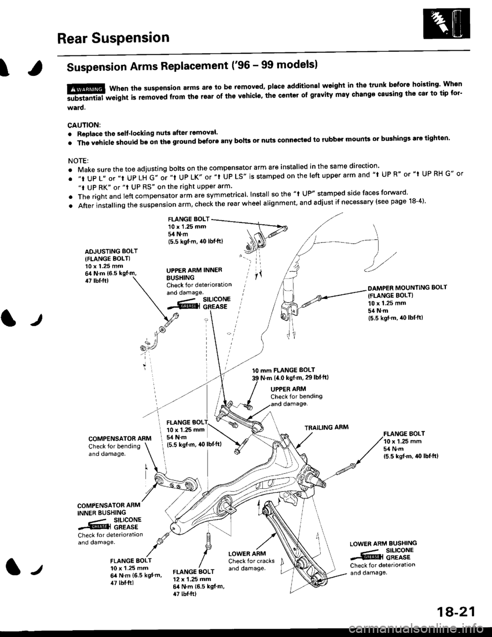
ISuspension Arms Replacement ('96 - 99 modelsl
tffi Whsn ths suspension arms ar6 to be removed. place additionsl weight in the trunk bafore hoisting' Wh€n
-substantial weight is removed ftom th6 teal of ths vehicl6, the center of gravity may change causing ths cat to tip tor'
ward.
CAUTION:
. Replace the selt-locking nuts after removal.
.Thgvehic|eshouldb€onthggroundboforeanybohsornutsconnectodtorubbelmountso]bughingsaretighton.
NOTE:
. Make sure the toe adjusting bolts on the compensator arm are installed in the same direction'
. ,,t UP 1,, or ,,t UP LH G,. or ,.t UP LK,, or "t UP LS'. is stamped on the |eft upper arm and ,,t UP R" or "t UP RH G., or
"t UP RK" or "t UP RS" on the right upper arm'
. The rightand left "ornp"n""to, uitt rre symmetrical lnstall sothe "t UP" stamped side faces forward'
.Afterinsta||ingthesuspens|onarm,checktherearwhee|alignment,andadjustifnecessary(seepagelS-4).
FLANGE BOLT10 x 1.25 mm54 N.m
ADJUSTING BOLT(FLANGE BOLTI10 x 1.25 mm
BUSHINGCheck for deteriorationand oamage.
(5.5 kgf'm, 40 lbf'ftl
UPPER ARM INNER
47 tbf.ftl
tJ
l0 mm FLANGE BOLT
N.m t4.0 kst m, 29lblftl
DAMPER MOUNTING BOLT(FLANGE BOLT}
10 x 1.25 mm
54Nm(5.5 kgd.m, iro lbf'ft)
FI.ANGE BOLT10 x 1,25 mm54 N.m(5,5 ksrf.m, 4{} lbf'ft}
UPPER ARMCheck for bendangdamage-
TRAILING ARM
COMPENSATOR ARM
Check for bendingano oamage,
COMPENSATOR ARM
INNER BUSHING
.- SILICONE.@] GREASE
Check tor deteriorataonand damage.
FLANGE BOLT10 x 1.25 mm64 N.m {6.5 kgt'm,47 lbf.ft)
LOWER ARMCheck for cracksano damage.
LOWEN ARM BUSHING
.,- SILICONE..i@l GREASECheck for deteriorationand oamage,FLANGE AOLT12 x 1.25 mm64 N.m {6.5 kgf m,47 tbf.ftt
FLANGE BOL10 x 1.25 mm
I 54 N.m
(5.5 ksrm, ao lbf'ftl
1A-21
Page 1146 of 2189

Rear Suspension
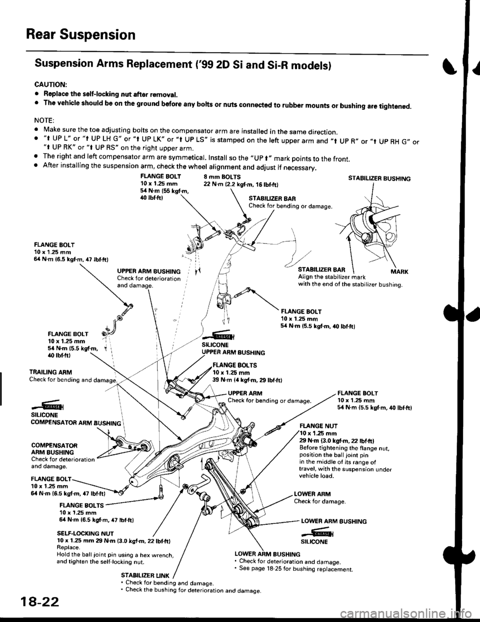
Suspension Arms Replacement ('gg 2D Si and Si-R models)
CAUTION:
. Roplace the self-locking nut after removal.' The vehicle should be on the gtound before any bohs or nuls connected to rubber mounts or bushing are tightened.
NOTE:
' Make sure the toe adjusting borts on the compensator arm are insta|ed in the same direction.. "t UP L" or "t UP LH G" or "t Up LK" or "l Up LS,, is stamped on the left upper arm and ,,t Up R,, or "t Up RH G,,"i UP RK" or "t UP RS" on the right upper arm.. The right and left compensator arm are symmeticar. Install sothe"upr"markpointstothefront.. After installing the suspension arm, check the wheel atignment and adiust if necessary,
FLANGE BOLT'10 x 1.25 mm54Nm155kgl.m,,rc lbf.ftl
8 rhm BOLTS22 N.m {2.2 kgf.m, 16 tbtfrlSTABILIZER BUSHTNG
FLANGE BOLT10 x 1.25 rnm54 N.m {5.5 kgt m, iro lbf.ft)
STAEILIZER BARCheck for bending or damage.
FLANGE BOLT10 x 1 .25 mm64 N m {5.5 kgf.m,47 lbtftl
FLANGE BOLT10 x 1.25 mm54 N.m 15.5 *gf.m,
and
UPPER ARM BUSHINGCheck for deteriorationAlign the stabitizer markwith the end ot the stabilizer bushing.
FLANGE BOLT'10 x 1.25 mm54 N.m 15.5 kgt.m, a0 lbtftl
stLrcoNEUPPER ARM BUSHINGiO lbf.ftl
TRAILING ARMCheck for bending and
EOLTS10 x 1.25 mm39 N m ll kgf.m, 29 lbf.ft)
UPPER ARMCheck for b€nding or damage.#@lstLtcoNECOMPENSATOR ARM BUSHING
COMPENSATORARM BUSHINGCheck for deteriorationand damage.
FLANGE NUTr '1.25 mm29 N.m {3.0 ksl.m,22 lbtft}Belore tightening the flange nut,position the ball joint pinin the middle ol its range oftravel, with the suspension undervehicle load.
LOWER ARMCheck for damage-
BUSHING
FLANGE BOLTl0 x 1.25 mm6l N.m 16.5 kg{.m, a7 lbt.ftl
FLANGE BOLTS10 x 1,25 mm64 N.m {6.5 kgf.m, 47 lbf.ftl
SELF.LOCKNG NUT
LOWER ARM
-GrstltcoNE10 x 1.25 mm 29 N.m (3.0 ksl.m, 22 tbtfrlReplace.Hold the ball ioinl pin using a hex w.enct.and tighten the selfjocking nut.
STABILIZEB LINK
LOWER ARM BUSHING. Check for deterioration and damaoe.' See page 18 25 for bushing replaciement.
' Check for bending and damage.. Check the bushing for deterioration ano oamage.
18-22
Page 1150 of 2189
Rear Damper
Removal
1. Bemove the rear wheels (see page 1g-22).
2. Remove the speaker cover and speaker (Hatchback).
Sedan and Coupe: Remove the trunk side panel (see
section 20).
3. Remove the two flange nuts.
FLANGE NUTS10 x 1.25 mm
4. Remove
FLANGE BOLT10 x 1,25 mm
Remove the flange bolt that connects the lower armto the trailing arm.
the flange bolt from the damper.
FLANGE BOLT'10 x 1 .25 mm
18-26
6. Lower the rear suspension, and remove the damper.
Page 1151 of 2189
IDisassembly/lnsPection
lr
Disassembly
1. Compress the damper spring with the spring com-
pressor according to the manufacturer's instruc-
tions, then remove the self-locking nut.
GAUTION: Do not compress the spring more than
necessary to remove the sell-locking nut.
STNUT SPRING COMPRESSOR:
lComm6rcially .vailablelERANICKo T/N MST-580A, T/N 7200, or equivalent
Release the pressure from the spring compressor.
then disassemble the damper as shown on page 18-
(|-r
lnspection
1. Reassemble all parts, except the sprlng.
2. Push on the damPer as shown.
WOODEN BLOCK
Check for smooth operation through a full stroke,
both compression and extension.
NOTE: The damper should move smoothly lf it
does not (no compression or no extension), the gas
is leaking, and the damper should be replaced.
Check Jor oil leaks, abnormal noises, and binding
during these tests.
{cont'd)
18-27
Page 1153 of 2189
Rear Damper
Ilnstallation
'1. Lower the rear suspension, and position the
damper with the spring stop pointed toward the left
SPRING STOP
2. Loosely installthe two flange nuts
FLANGE NUTS10 x 1.25 mm49 N.m (5 kgf.m, 36 lbt'ft)
Tighten these nuts in
step 7.
lr
3. Loosely install the flange bolts.
FLANGE BOLT10 x 1.25 mm54 N.m {5.5 kgf m, 40 lbt'ft1
FLANGE BOLT10 x 1 .25 mm54 N.m {5.5 kgf.m,/r0 lb{.ft|
7.
Raise the rear suspension with a floor jack until the
vehicle just lifts off the safety stand.
!@@ Tne floor iacx must be securelY Posi-
tionod or peFonal iniury may rssull
Tighten the flange bolts.
Tighten the two flange nuts on top of the damper to
the specified torque.
Check the rear wheel alignment and adjust if neces-
sary (see page 18-4).
1A-29
Page 1156 of 2189
Special Tools
Ref. No. I Tool Numbo]DescriplionOty I Page Reference
o07HAE - SG00100
07JAG - SD40100
07914 - SA50001
Brake Spring Compressor
Pushrod Adjustment Gauge
Snap Ring Pliers
19-28, 33
19-22
o@
19-2
Page 1157 of 2189
Component Locations
I
lndex
ERAKE PEDALInspectron andAdjustment, page 19 5
BRAKE HOSES LINESInspection/Torque specif ications, page 1 9-39Hose Replacement, page 19-40
MASTER CYLINDER/BRAKE BOOSTERRemoval/lnstallation, page 19 21Pushrod Clearance Adjustment, page 19_22
Brake Booster Inspection, page 19-23
lJ
PARKING BRAKE CASLEinspection and Replacement,page 19 41
FRONT BRAKESNOTE: There are two types offront brake calipers:The caliper types can be identitied by the "5410"
or "2056" stamped on the caliper body. Check thetype ot the brake caliper betore servicing.Front Brake Pads5410 Type: page 19-82056 Typer page 19 10Front Brake Disc, page 19-12Front Brake Caliper5410 Type: page 19-132056 Type: page 19-14
BBAKEAdiustment, page 19-6REAR ORUM BRAKESInspection, page 19-36
Brake Shoe Beplacement, page 19'37
REAR DISC BRAKESRear Brake Pads, page 19 24Rear Brake Disc, page 19 26Rear Brake Caliper, page 19'27
lJ
19-3