Page 1180 of 2189
Rear Brake Disc
Disc Runout Inspection
1.Loosen the front wheel nuts slightly, then raise thevehicle, and suppon it on safety stands. Removethe front wheels.
Remove the brake pads (see page 19-24).
Inspect the disc surface for damage and cracks.Clean the disc thoaoughly, and remove a
rust.
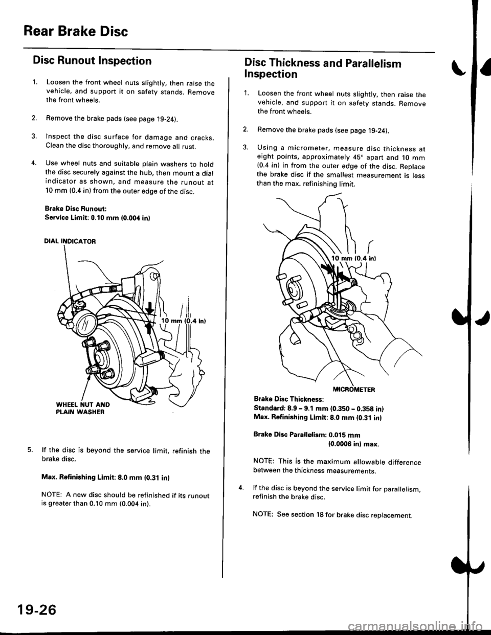
Use wheel nuts and suitable plain washers to holdthe disc securely against the hub. then mount a dialindicator as shown. and measure the runout at10 mm (0.4 in) from the outer edge of the disc.
Brake Disc Runout:
Service Limit:0.10 mm {0.00,t in)
5. lf the disc is beyond the service limit, refinish thebrake disc,
Max. Retinishing Limit: 8.0 mm {0.31 in)
NOTE: A new disc should be refinished if its runoutis greater than 0.10 mm (0.004 in).
19-26
Disc Thickness and Parallelism
Inspection
1. Loosen the front wheel nuts slightly, then raise thevehicle, and support it on safety stands. Removethe front wh6els.
2. Remove the brake pads (see page j9-24).
3. Using a micrometer. measure disc thickness aterght points, approximately 45" apart and 1o mm{0.4 in) in from the outer edge of the disc. Replacethe brake disc if the smallest measurement is lessthan the max. refinishing limit.
Brake Disc Thickness:
Standard: 8.9 - 9.1 mm (0.350 - 0.358 in)Max. Rsfinishing Limit: 8.0 mm {0.31 in}
Brake Disc Parallelirm: 0.015 mm(0.0006 inl msx.
NOTE; This is the maximum allowable differencebetween the thickness measurements.
4. lf the disc is beyond the service limit for Darallelism.refinish the brake disc.
NOTE; See section 18 for brake disc replacement.
Page 1181 of 2189
Rear Brake Caliper
Disassembly
@f l',lever use an air hose or dry brush to clean
assemblies.
. Use an OsHA-approved vacuum cleaner to
brake
avoid
breathing brake dust.
. Contaminated brake discs or pads reduce stopping
ability.
CAUTION:
. Do not spill brake tluid on the cal; h may damage the
paint; if brake fluid does contact the paint, wash ii
ofl immediatelY with water.
. To prevent spills, cover the hose ioints whh rags or
shop tow€ls.
. Clean all parts in brake fluid and air dry; blow out all
passagss with complessed air.
1. Remove the caliper shield (see page 19-24).
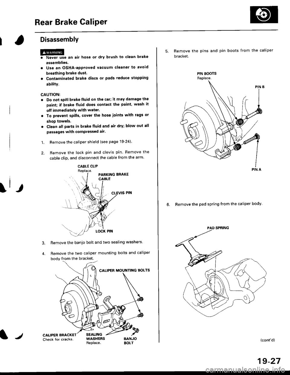
2. Remove the lock pin and clevis pin. Remove the
cable clip, and disconnect the cable from the arm
CABLE CLIP
Remove the banjo bolt and two sealing washers
Remove the two caliper mounting bolts and caliper
body from the bracket.
CALIPER MOUNTNG AOLTS
CALIPER BRACKETCheck for cracksSEALINGWASHERSReplace.BANJOBOLT
5, Remove the pins and pin boots from the caliper
bracket.
6. Remove the pad spring from the caliper body
PIN A
(cont'd)
19-27
Page 1188 of 2189
Rear Brake Caliper
Reassembly (cont'dl
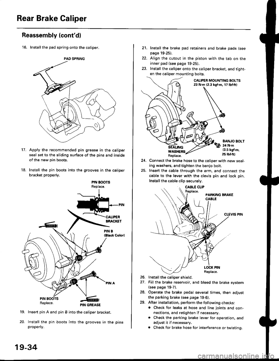
'16. Installthe pad spring onto the caliper.
Apply the recommended pin groase in the caliper
seal set to the sliding surface of the pins and inside
of the new pin boots.
Install the pin boots into the grooves in the caliper
bracket properly.
PIN BOOTSReplsce.
(Bl.ck Colorl
PINRepl6ce.
19. Insert pin A and pin B into the caliper bracket.
20. Install the pin boots into the grooves in thepropefly.
PAD SPRING
11.
PIN GREASE
19-34
pr ns
22.
21. Install the brake pad retainers and brake pads (see
page 19-25).
Align the cutout in the piston with the tab on the
inner pad (see page 19-25).
Install the caliper onto the caliper bracket. and tight-
en the caliper mounting bolts.
CALIPER MOUNTING BOLTS23 N.m {2.3 kg{.m. 17 lbf.ft)
WASHERSReplace.
BANJO BOLT34 N.m13.5 kg{.m.25 rbtft)
24.Connect the brake hose to the caliper with new seal,
ing washers, and tighten the banjo bolt,
Insert ths cable through the arm, and connect the
cabls to the lever with the clevis pin and lock pin.
Install the cable clip securely.
CLEVIS PIN
-t
//t
LOCK PINRoplace.
26. Install the caliDer shield.
27. Fill the brake reservoir, and bleed the brake svstem(see page 19-71.
28. Operate the brake pedal several times, then adjust
the parking brake (see page 19-6).
29. After installation, perform the following checks:. Check for leaks at hose and line joints and con-nections, and retighten if necessary.. Check the parking brake lever for operation, and
adjust it if necessary.
. Check for brake hose for interference or twistinq.
Page 1189 of 2189
Rear Drum Brake
Index/lnspection
'1.
a
a
Never use an air hose or dly brush to clean brake assemblies,
Use an OSHA approved vacuum cleanar to avoid breathing brake dust,
Contaminated brake linings or drums reduce stopping ability.
Block the tront wheels before iacking up ths r€ar of lhe vehicle.
Block the front wheels, loosen the rear wheel nuts slightly, support the rear of the vehicle on safety stands, then
remove the rear wheels.
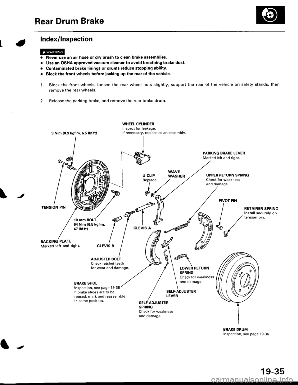
2. Release the parking brake, and remove the rear brake drum.
I N m 10.9 kgtm, 6.5 lbf.ftl
TENSION PIN
10 mm BOLT6,1N m 15.5 kgf m,47 tbf.ft)
WHEEL CYLINDERInspect for leakage.lf necessary, replace as an assembly.
u-cLrPReplace.
WAVEWASHER
PARKING BRAKE LEVERMarked left and right.
Check for weaknessano oamage,
UPPER RETURN SPRING
I
@JPIVOT PIN
BACKING PLATEMarked lelt and right-
/
€f-l.^
I I
*'t")
ctEv'sB
/ (t
/ ,.ro,".r r.*,"n
/ , Install securely on
| / tension pin.
d"/
IU
ADJUSTER BOI-TCheck ratchet teethfor wear and damage.LOWER RETURNSPRINGCheck for weaknessand oamage.BRAKE SHOEInspection, see page 19-36lf brake shoes are to bereused, mark and reassemblein same position.
SELF.ADJUSTERLEVEB
SELF-ADJUSTERSPRINGCheck for weaknessano oamage.
BRAKE DRUMInspection, see page '19 36
t
19-35
Page 1192 of 2189
Rear Drum Brake
Brake Shoe Reassembly {cont'dl
Connect the parking brake cable to the parking
brake lever.
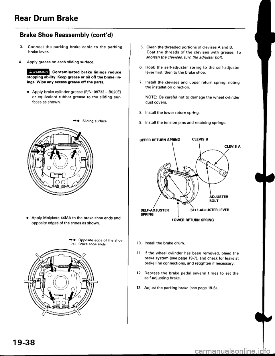
Apply grease on each sliding surface.
!@ contaminated brake linings reduce
stopping ability. Keep grease or oil off the blake lin-
ings. Wipe any excess grease off the parts,
. Apply brake cylinder grease {P/N: 08733 - 8020E)
or equivalent rubber grease to the sliding sur-
faces as shown.
+a Sliding surlace
Apply Molykote 44MA to the brake shoe ends and
opposite edges ofthe shoes as shown.
_' o Opposite edge of the shoe+O Brake shoe ends
19-38
13.
5. Clean the threaded portions of clevises A and B.
Coat the threads of the clevises with grease. To
shoften the clevises, tun the adjuster bolt.
6. Hook the self-adjuster spring to the self-adjuster
lever first, then to the brake shoe
7. Install the clevises and upper return spring. noting
the installation direction.
NOTE: Be careful not to damage the wheel cylinder
dust covers,
8. Install the lower return spring.
9. Install the tension pins and retaining springs.
uppER RETURT{ SpRtNG CLEVIS B
CLEVIS A
Installthe brake drum.
lf the wheel cylinder has been removed, bleed the
brake system (see page 19-7), and check for leaks at
brake line connections, and retighten if necessary.
Depress the brake pedal several times to set the
self-adjusting brake.
Adjust the parking brake (see page 19-6).
't0.
11.
12.
LOWER RETURN SPRING
Page 1194 of 2189
Brake Hoses/Lines
Hose Replacement
CAUTION:
. Bgfore reagsembling, chgck that all parts are free of
dust and othor foroign particles.
. Repl8ce parts with new ones whenever specified to
do so,
. Do not spill brake fluid on th6 vehicle; it may damage
tho paint; if brake fluid does contact the paint, wash
it off immediately with water.
1.Replace the brake hose if the hose is twisted, cracked,
or if it leaks.
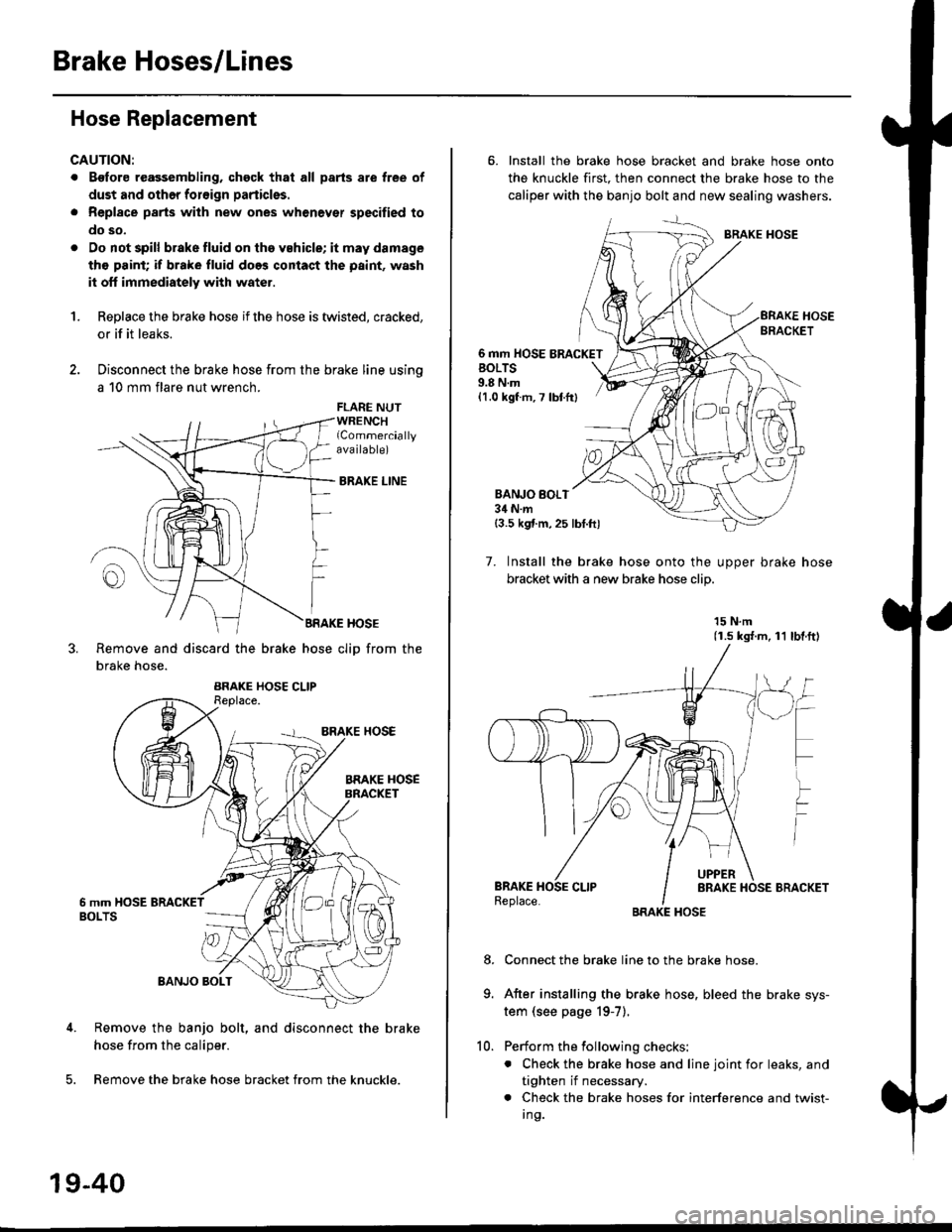
Disconnect the brake hose from the brake line using
a 10 mm flare nut wrench.
FLARE NUTWRENCHlCommerciallyava ilable)
BRAKE LINE
BRAKE HOSE
Remove and discard the brake hose cliD from the
brake hose.
Remove the banjo bolt, and disconnect the brake
hose from the caliper.
Remove the brake hose bracket from the knuckle.
19-40
10.
6. Install the brake hose bracket and brake hose onto
the knuckle first. then connect the brake hose to the
caliper with the banjo bolt and new sealing washers.
BRAKE HOSE
6 mm HOSE BRACKETBOLTS9.8 N.m{1.0 kgf m, 7 lbtfr}
BANJO BOI.T34 N.m{3.5 kgf.m,25 lbt.ftl
7. Install the brake hose onto the uooer brake hose
bracket with a new brake hose clip
15 N.m(1.s ks{.m, 11 lbl.ftl
Connect the brake line to the brake hose.
After installing the brake hose, bleed the brake sys-
tem (see page 19-7).
Perform the following checks:
. Check the brake hose and line joint for leaks, and
tighten if necessary.
. Check the brake hoses for interference and twist-
I ng.
8.
Page 1197 of 2189
Special Tools
Ret. No. I Tool Number I Description I O,V I page Reference
(!) I 07PM- 0010100 I SCS Service Connector t I 19_s6
19-44
Page 1212 of 2189
Le
\.t
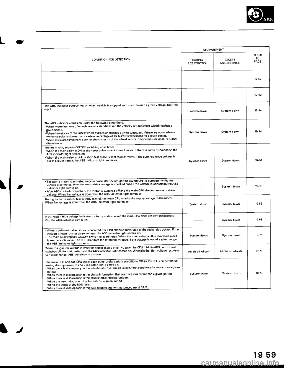
CONDITION FOR DETECTION
MANAGEI\,4ENT
FEFERTOPAGEDUNINGABS CONTFOLEXCEPTABS CONTAOL
19-60
19-62
The ABS indicator lighl cones on when vehicle is stopp€d and wheel sensor a given vohaqe does nol
19 64
The ABS indicaror comes on under th€lollowing conditions.When morethan one otwheels are a standstiland thelelocirv otthe fastest wheel reaches a
' fohen th. velocity of the faslesl wheel reaches or exceds a given sped, and it there ar€ somewh@lswhose velocity is slowe.lhan a cenain percenlage oi lh€ fast6t wheelsped for 3 given period. when rhere are lemporary open or short ctcuits ol rhe wheel sonsor' chipp€d pulser gear, orsrgnalorslJrbaaLe
19 64
The main relay repeats ON/OFF switching atalltimes.WhenthemainrelayisON,ashortt$tpulseissentloeachvalve lfthere s some dis'repa ncv, lheABS indicalor lightcomes on.. When rhe main relay is OFF, a shonl€sl pulse is s€nlto each valve lfth6 solenoid drive voltage rsout ol a qiven range, the ABS ndicalor lighl comes on19-66
'The pump nolot s activaled orc€ o' Mrce sfier every gn't'on sw'lch ON (ll) operarion whrle lte -^vchicle acLelerales lrenthemolorotivevo'taSersrhecled When lhevolla96 rs abnormar,lre Absindicaror llghl comes on.. Afte. ABS ;onl rol com pletion, the moror isswitched ofi 6nd the main CPU checks the molor dnvevoltase. when rhe vortase is abnormsl, the ABS indicato49!!!99!:l!:_-
19-68
D!rino an active motor lesl or AAS control,lhe main CPU checks ihe supplv voltage to the motor'whe;lhe vohage s abnofmal, the ABS indicator lightcomes on19,68
lirhe moror drvevoltage indicates molot operalion when the main cPU does notswilch the motoroN, rhe ABs indicaro. comes on19-64
. Wh"" " ".1"".1d ""1r. f"llure is detecred, the CPU checksth€ voltage ofthe main rel6v output lllhevohaqe is lowerthan 6 given vohage, theABS indicator light comes on. The ;ain r€lay repeats ON/OFF switching ar a!ltimss when the main rel.v is ofi, a shorl l6st pulse
is sent ro €ach valve. The CPU mon tors the reJer€nce vohage ll the vohage is out ot a g iven range'
the ABS indic.tor lightcomes on
19 71
wt'",, rt'e lgnitlon rottag" is ower or higherthan a given voltage,lhe CPU inhibils ABSlonlrolandswirches oli the ma in relaY, 6nd the ABS indicaror lig ht com€s on When the ig n ilion vohage recove'sto normal f6ng6, ABS inhibition is canceled.19.73
rimln CpU anO suU CeU ch€ck each other undercertain condnions. Whon rhe CPUS dstectthe fol'lowing discrepanaies, rhe ABS indicator light comss on. whe; rh€re is discGpancv n lhacarculated wheelspeed velocirv thar continuosJor more than a given
.i^/hen rhere is discrcoancv in the ehase informalion lhat continuesfor morerhan a given period' When rhere is discrepancY in thecalculared conlfol pa.amerer'. When thewatch dog conrrolp!lsetailslof a given penod. When th6 checkotth€ ROM tai1s.. when there is disrepancy inrhe data roading.nd wriung prcledurc ot RAM
19 7'l
tr
19-59