Page 1080 of 2189
Troubleshooting
General Troubleshooting (cont'd)
Assist (excessively light steering) athigh speed.
Shock or vibration when wheel isturned to {ull lock.
Steering wheelwill not returnsmoothly.
lf the problem is not corrected byadiusting the rack guide, adjustthe front wheel alignment lseesection 181.
Check the rack guide for properadiustment (see page 17 33).
Check the rack guide for properadjustment (see page 17-33).
Rack guide is adjusted properly.
lfthe problem is not corrected byadjusting the rack guide, replacethe gearbox.Check the belt for slippage andaolust as necessary {see page11 32).
A and B cylinder lines are nor-mal, check wheel alignment (seesection 18).
Wheel alignment is abnormal,adjust as needed.
Wheel alignment is normal.Check the steering wheel opera-tion and power assist check {seepage lT-30).
It the measurements are out ofspecifications, adjust the ra ckguide.
lf the problem is not corrected byadjusting the rack guide, replacethe gearbox.
17-24
Page 1081 of 2189
/
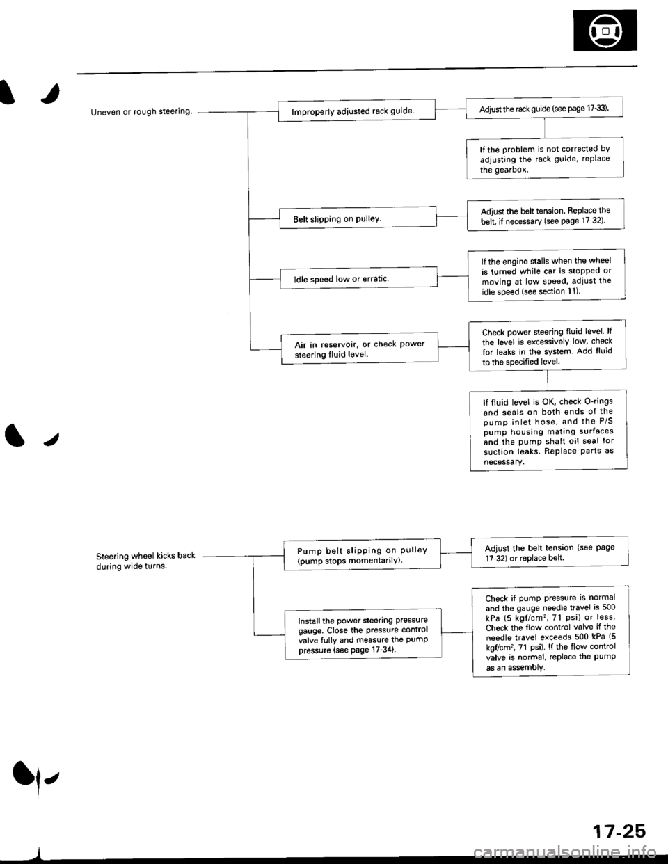
Uneven or rough steering
Steering wheel kicks back
during wide t!rns.
ll,
)
Adjust the rac* guide (see page 17-3).
lf the problem is not corrected bY
adjusting the rack guide, replace
the gearbox.
Adiust the belt tension. Feplace the
belt, il necessary (see Page 17 32).
lfthe engine stalls when the wheel
is turned while car is stopped or
moving at low speed, adjust the
idle spe€d (see section 11)
ldle speed low or erratic.
Check power sleering fluid level lf
the level is excessively low, check
lor leaks in the system. Add lluid
to the specified level.
Air in reservoir, or check Powersteering Iluid level.
lf ltuid level is OK, check O-rings
and seals on both ends of thepump inlet hose, and the P/Spump housing mating surfaces
and the pumP shaft oil seal for
suction leaks. RePlace Parts as
nocessary.
Adjust the belt tension (see Page17 32)or replace belt.Pump belt sliPPing on PLrlleY(pump stops momentarilY)
Check if pump press{rre is normal
and the gauge needle travel is 500
kPa (5 kgl/cm?, 7l Psi) or less.
Chock the flow control valve if the
needle travel exceeds 500 kPa (5
kgflcm'�, 71 Psi). l{ the flow control
valve is normal, replace the PumPas an assemoly.
Install the power steering pressure
gauge, Close the Pressure contrcl
valve fully and m6ssure the PumPpressure {s€e page 17-34}.
17 -25,
Page 1082 of 2189
Troubleshooting
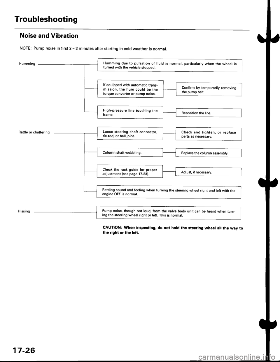
Noise and Vibration
NOTE; Pump noise in first 2 - 3 minutes after starting in cold weather is normal.
Humming
Rattle or chattering
Humming due to pulsation of fluid is normal, particularlv when the wheel isturned with the vehicle stooDed.
lf equipped with automatic trans-mission, the hum could be thetorque conveater or pump noise.
Confirm by temporarily removingthe pump belt.
High-pressure line touching theframe.Reposition the line.
Loose steering shaft connector,tie-rod. or balljoint.Check and tighten, or replacepaats as necessary.
Column shaft wobbling.Replace the column assembly.
Check the rack guide tor properadjustment (see page 17,33).Adiusi, if necess€ry.
Rattling sound and feeling when turning the steering wheel raght and left with theengine OFF is normal.
Pump noise, though not loud. trom the valve body unit can be heard whon turn-ing the steering wheel right or left. This is normat.
CAUTION: When imp€sting, do not hold the steering wheet a[ the way tothe right or the left.
17-26
Page 1083 of 2189
)
Pump noaseGrating noisefrom pump
Pump gear nois€
Check the tluid level.
lf low, fill the reservoir to the
proper level, and check lor leaks.
Tighten or replace as nocessary.
Cavitation caused bY air bubbles
in the fluid.
Check lor a crushed suction hose
or a loose hose clamp allowing
air into the suction side of the
sy$em.Tighton or roplace as necossary.
NOTE: Pump noise uP to 2 - 3
minutes alter starting in cold
weather is normalCompare pumP noise at operating
temperature to simular vehicle.
lf pump nois€ is abnormallY loud,
remove and inspect the PUmP for
w6ar and damage (see Page 17-
41).
lz/
Rattle or chattgring
17-27
Tighten or replace the Pulley.lf shatt is loose, rePlace thepump.
tr
Page 1086 of 2189
Inspection and Adjustment
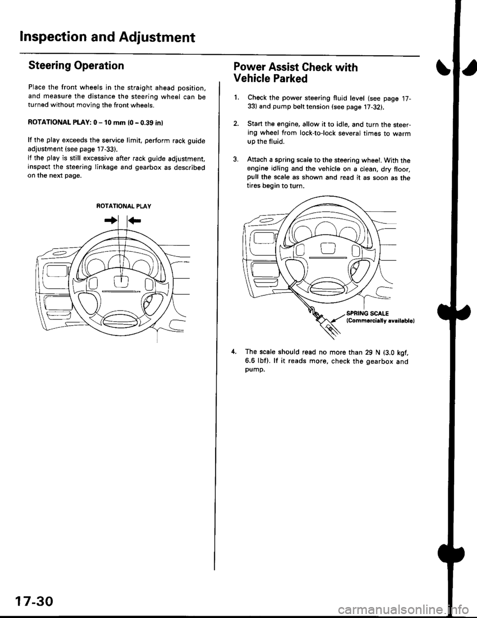
Steering Operation
Place the front wheels in the straight ahead position,
and measure the distance the steering wheel can beturned without moving the front wheels.
ROTATIONAL PLAY: 0 - 10 mm l0 - 0.39 inl
lf the play exceeds the service limit. perform rack guide
adjustment (see page 17-33).
lf the play is still excessive after rack guide adjustment.inspect the steering linkage and gearbox as describedon the nel(t pag€.
ROTATIONAL PLAY
17-30
Power Assist Gheck with
Vehicle Parked
1. Check the power steering fluid level (see page 17-33) and pump belt tension (see page 17-32).
2. Start the engine, allow it to idle. and turn the steer-ing wheel from lock-tolock several times to warm
up the fluid.
3. Attach a spring scale to the steering wheel. With theengine idling and the vehicle on a clean, dry floor,pull the scale as shown and read it as soon as thetires begin to turn.
The scale should read no more than 29 N (3.0 kgf.
6.6 lbf). lf it reads more, check the gearbox andpump,
D0
Page 1087 of 2189
ISteering Linkage and Gearbox
TIE-ROD END BALL JOINT
Inspect for faulty movement
and damage.
STEERING COLUMN
Inspect for loose column
mounting bolts and nuts
BOOTInspectdamage and deteriorataon
STEERING GEARBOXlnspect for loose mounting bolts.
GEARBOX MOUNTING CUSHIONS
Inspect f or deterioration
STEERING JOINTSCheck for loose joint bolts.
l./
TIE-ROD LOCKNUTfor loose locknut
BALL JOINT BOOT
Inspect for damage and deteriorataon'
See page 17-68lor replacement.
SHAFT GROMMETInspect for damage and deteriorataon.
lrz
17-31
Page 1089 of 2189
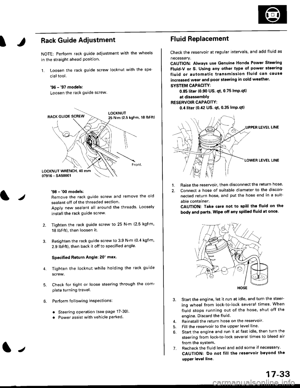
IRack Guide Adjustment
NOTE: Perform rack guide adjustment with the wheels
in the straight ahead Position.
1. Loosen the rack guide screw locknut with the
cialtool.
'96 - '97 models:
Loosen the rack guide screw
'98 - '00 models:
Remove the rack guide screw and remove the old
sealant off of the threaded section.
Apply new sealant all around the threads. Loosely
installthe rack guide screw
Tighten the rack guide screw to 25 N'm (2.5 kgf'm.
18 lbf.ft), then loosen it.
Retighten the rack guide screw to 3 9 N'm (0.4 kgim,
2.9 lbf.ft), then back it off to specified angle.
Specified Return Angle: 20" max.
Tighten the locknut while holding the rack guide
screw.
Check for tight or loose steering through the com-
plete turning travel.
Perform following insPections:
. Steering operation (see page 17-30).
. Power assist with vehicle parked.
4.
LOCKNUT WRENCH, 40 mm
lr
17-33
Fluid Replacement
Check the reservoir at regular intervals, and add fluid as
necessary.
CAUTION: Always us€ Genuine Honda Power Stearing
Fluid-V or S. Using any other type of power sto€ring
tluid or automatic transmission lluid can cause
increased wear and poor steering in cold weathor.
SYSTEM CAPACITY:
0.85 liter 10.90 US' qt,0.75 lmp'qt)
at disassembly
RESERVOIR CAPACITY:
0.4 liter (0.42 US. qt, 0.35 lmP.qt)
LEVEL LINE
LOWER LEVEL LINE
1. Raise the reservoir, then disconnect the return nose.
2. Connect a hose of suitable diameter to the discon-
nected return hose, and put the hose end in a suit-
able container.
CAUTION: Take care not to spill tho fluid on the
body and parts. Wipe off any spill€d fluid at oncs'
3. Start the engine, let it run at idle, and turn the steer-
ing wheel from lock-to-lock several times When
fluid stops running out of the hose, shut off the
engine, Discard the fluid.
4. Reinstall the return hose on the reservoir'
5. Fill the reservoir to the upper level line.
6. Start the engine and run it at fast idle, then turn the
steering trom lock-to-lock several times to bleed air
trom the system.
7. Recheck the fluid level and add some it necessary.
CAUTION: Do not fill the reservoir beYond the
upper l€vel line.
HOSE
Page 1093 of 2189
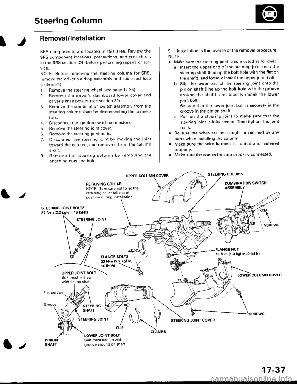
Steering Column
I
Removal/lnstallation
SRS components are located in this area. Review the
SRS component locations, precautions, and proceclures
in the SRS sectron (24) before pertorming repairs or ser-
vice.
NOTE: Before removing the steering column for SRS,
remove the driver's airbag assembly and cable reel lsee
section 24).
1. Remove the steering wheel (see page 17 35).
2. Remove the driver's dashboard lower cover and
driver's knee bolster (see section 20).
3. Remove the combination switch assembly from the
steering column sha{t by disconnecting the connec-
tors.
4. Disconnect the ignition switch connectors.
5. Remove the steering joint cover.
6. Bemove the steering joint bolls.
7. Disconnect the steering ioint by moving the joint
toward the column, and remove it from the column
shaft.
8. Remove the steering column by removing the
attaching nuts and bolt.
UPPER
RETAINING COLLABNOTE: Take care not to let the
retaining collar fall out ofposition during installation.
STEERING JOINT BOLTS22 N.m {2.2 kgf.m, 16lbtft}
9. Installation is the reverse of the removal procedure
NOTE:
. Make sure the steering joint is connected as follows:
a. Insert the upper end of the steering ioint onto the
steering shaft (line up the bolt hole with the flat on
the shait), and loosely install the upper joint bolt.
b. Slip the lower end of the steering joint onto the
pinion shaft (line up the bolt hole with the groove
around the shaft), and loosely install the lower
joint bolt.
Be sure that the lowei joint bolt is securely in the
groove in the pinion shaft.
c. Pull on the steering joint to make sure that the
steering joint js fully seated. Then tighten the ioint
bolts.
. 8e sure the wires are not caught or pinched by any
parts when installing the column
. Make sure the wire harness is routed and fastened
properly.
. Make sure the connectors are properly connected.
STEERING COLUMN
COMBINATION SWITCHASSEMBLY
FLANGE NUT13 N.m {1.3 kgl.m.9 lbf ft)
COLUMN COVER
FLANGE BOLTS22Nm12.2kgl'm,16 tbt.tr)
UPPER JOINT BOLTBolt musl line upon shaft.
Groove.
LOWER JOINT BOLT8oh must line up wrthgroove around on shaft.
CLIP
J
JOINT COVER
17-37