Page 1438 of 2189
![HONDA CIVIC 1996 6.G Workshop Manual Troubleshooting
Compressor lcontdl
COMPRESSOR CLUTCH RELAY4P SOCKET
l--;l
12 |---r--]l.l3 |L-J--J
] BLK/YEL
A(v)
!
ECM/PCM CONNECTOR A I32P}
Wire side of female terminats
*Howto use the backprobe set HONDA CIVIC 1996 6.G Workshop Manual Troubleshooting
Compressor lcontdl
COMPRESSOR CLUTCH RELAY4P SOCKET
l--;l
12 |---r--]l.l3 |L-J--J
] BLK/YEL
A(v)
!
ECM/PCM CONNECTOR A I32P}
Wire side of female terminats
*Howto use the backprobe set](/manual-img/13/6068/w960_6068-1437.png)
Troubleshooting
Compressor lcont'dl
COMPRESSOR CLUTCH RELAY4P SOCKET
l--;l
12 |---r--]l.l3 |L-J--J
] BLK/YEL
A(v)
!
ECM/PCM CONNECTOR A I32P}
Wire side of female terminats
*Howto use the backprobe setsConnect the backprobe adapters to the stackang patch cords, andconnect the cords to a multimeter. Using the wire insulation as aguide for the contoured tip of the backprobe adapter, gently slidethe tip into the connector from the wire side until it comes in con-tact with the terminalend ofthe wire (see section 11).
Frcm page 22-12
To page 22-15
Check Ior an open in the wire;1. Disconnecl the jumper wire.2. Turn the ignition swatch ON (ll).
3. l\4easure the voltage betweenthe No. 4 terminal of the com-pressor clutch relay 4P socketand body ground.
Repair open in the wire betw€enthe No. 17 fuso and the compres-sor clutch relav.
Check for an open in the wira:1. Turn the ignition switch OFF,then reinstall the compressorclutch relay.2. Make sure the A/C switch isOFF, then turn the ignitionswitch ON (ll).
3. Using a *Backprobe Set (T/N07SAZ 0010004), measurethe voltage between the No.17 terminal oI the ECM/PCMconnector A (32P) and bodyground with the ECM/PCMconnectors connected.
Repair open in the wirc betweonthe compressor clutch relay andthe ECM/PCtvt.
ls there battery voltage?
Page 1440 of 2189

Troubleshooting
Gompressor (cont'dl
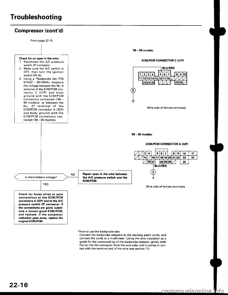
'96 -98 models:
ECM/PCM CONNECTOR C 13lPI
Wire side ot female terminals
'9!t - 00 mod.bi
ECM/PCM CONNECTOR A I32P)
Wire side ot female terminals
*How to use the backprobe setsConnect the backprobe adapters to the stacking patch cords, andconnect the cords to a multimeter. Using the wire insulation as aguide for the contoured tip of the backprobe adapter, gently slidethe tip into the connector from the wire side until it comes in con-tact with the terminal end ofthe wire {see section 11}.
From page 22-15
Check for an open in thg wire:'1. Reconnect the A"/C pressure
switch 2P connector.2. Make sure the A/C switch isOFF, then turn the ignitionswitch ON (ll).
3. Using a *Backprobe Set {T/N07SAZ - 001000A), measurethe voltage between the No. 5terminal of the ECM/PCM con-nector C (31P) and bodyground with the EcM/PcMconnectors connected ('96 -
98 models), or between theNo. 27 terminal of theECM/PCM connector A (32P)
and body ground with theECM/PCM connectors connected ('99 - 00 models).
Rapdir open in tho wi?e botwaonthe A/C pr..-ruro lwitch rnd th.ECM/PCM.
Check lor loo3e wires or ooolconnections at the ECM/PCMconnectoB A l32P) and at the A/Cpressure switch 2P connector, lfthe connections are good, substi-tute a known-good ECM/PCM,and recheck. lf the svmptom/indication goos away, repbce theoriginal ECM/PCM.
31501E91011
tat6l11E1921222321
BLU/RED
22-16
Page 1573 of 2189
lgnition System
-Circuit Diagram: '96 - 97 models
.i-
8LU
I
nBLU BLU I
tl
lnI TESTI TACHOMETEF\-7 CONNECTOR
TACHOMETERTCM (CW)
J-) {sh,eldinsr't I
tfYEL BBN/BLK
+l
I:
G101
$t+++
UNDER HOOD FUSE/ RELAY 8OX
BLh TEL YEL GBN
BLKlYEL
IAl
BLK/YEL YELIGFN
IGN]TIONCOL
TDCrTop dead cenlerCKP: Crankshall postionCYP Cylnder poslon
TDC]CKP]CYP SENSoR
" *]BLU'*2 WHI BLU
IGNITION CONIROLMODULE (CM)
/ Has b'r ll n\I iorse I
rUSE FE-AV BO}
*u r-. .-*---{<9ot # u,,."r. | |
\j/ El v
tl
23-103
Page 1577 of 2189
el -Distributor Overhaul
HITACHI:
TOC/CKP/CYP
DISTRIBUTOR IGNITION {DI} HOUSINGCheck for cracks and damage.
Troubleshooting, section 1 1
Do not disassemble.
CAP SEALCheck for damage.
IGNITION CONTROL MODULE (ICMI
Input Test, page 23'109
IGNITION {DI) CAP
Check for cracks, wear,damage, and fouling.Clean or replace,
{cont'd)
23-107
Test, page 23_110
Page 1578 of 2189
lgnition System
Distributor Overhaul (cont'dl
TEC:
IGNITION CONTROLMODULE IICM'Input Test, page 23-1
DISTRIBUTOR IGNITION {DI} HOUSINGCheck for cracks and damage.
COVER
DISTRIBUTOR IGNITION IDI) ROTOB
CAP SEALCheck for damage.DISTRIBUTOR IGNITION {DII CAPCheck for cracks, wear,damage, and fouling.Clean or replace,
IGNITION COILTest, page 23-110
O-RINGReplace
\
I
@
TDC/CKP/CYP S€NSORTroubleshooting, section 1 1Do not disassemble.
WHT/BLU
23-104
Page 1739 of 2189

)
Troubleshooting
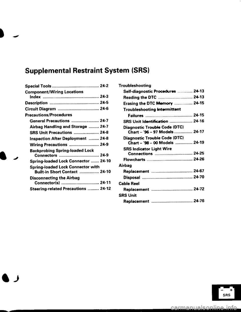
Sef f -dia gnostic Proctdurcs ............. 2+13
Reading the DTC .............................. 2+13
Erasing the DTC Mcnrory ................ 24-15
Troubleshooting h.ttnitt.nt
Failures ..............24-15
SRS U n it ldcntificrtion .................... 24- 1 6
Diagnostic Troublc Code (DTC)
Chart - '96 - 97 Models..."'."....... 24-17
Diagnostic Trouble Code (DTCI
Chart - '$ - 00 Models '.........""' 24'19
SRS lndicaror Light Wire
connections ...'.,24-25
Ff owcharts ........,,,,.24-26
Airbag
Repfacemant ...'.'...24-67
Disposaf .................24'70
Cable Reel
Repfacement .........24'72
SRS Unh
Repfacement ..'......24'76
l-l
-+
sRs
Supplemental Restraint System (SRSI
Speciaf Tools ... ...........24'2
Component/Wirin g Locations
fndex ................ ......24-3
Description ................ 24-5
Circuit Diagram ......." 24'6
Precautions/Procedures
Generaf Precautions ...............,,,,,,,.. 24-7
Airbag Handling and Storage .........24-7
SRS Unit Precautions ...................... 24-8
Inspection After Deployment ........' 24-8
Wiring Precautions ................... ....... 24'9
Backprobing Spring-loaded Lock
Connectors .......,24-9
Spring-loaded Lock Connectol ....,,. 24-10
Spring-loaded Lock Connector with
Built-in Short Contact ................. 24-10
Disconnecting the Airbag
Connector(sl .....' 24'11
Steering-related Precautions ...,.,.,,. 24'12
Page 1740 of 2189
Special Tools
Ref, No, I Tool NumberDescriptionOty I Page Reterence
o-,an*r
@
o/a*,
07HAz - SG00500
07PAZ 0010100
07sAz - TB4011A
0ITAZ - SZ5011A
07TAZ - 001020A
Deployment Tool
SCS Service Connector
SRS Inflator Simulator
SRS Simulator Lead C
Backprobe Adapter, 17 mm
1
1
I
1
2
24 10
24-14
24-42
24-42
24-30
* 1r Included in SRS Tool Set 07N4M - SM5000B*2: Use with the stacking patch cords from T/N 07SM 001000A, Backprobe Set.
o6\
o
t,4-2
Page 1747 of 2189

)
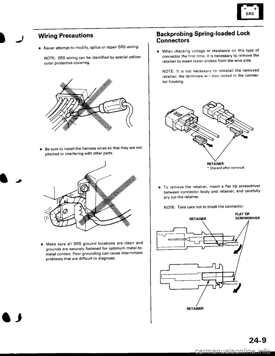
Wiring Precautions
. Never attempt to modify, splice or repair SRS wiring'
NOTE: SRS wiring can be identified by special yellow
outer Protective covering.
8e sure to install the harness wires so that they are not
oinched or interfering with other parts.
t
Make sure all SRS ground locations are clean and
grounds are securely fastened for optimum metal-to-
metal contact. Poor grounding can cause intermittent
problems that are difficult to diagnose.
a,
24-9
Backprobing Spring'loaded Lock
Gonnectors
. When checking voltage or resistance on this type of
connector the flrst time, it is necessary to remove lne
retainer to insert tester probes from the wire side.
NOTE: lt is not necessary to reinstall the removed
retainer; the terminals wi I stay locked in the connec-
tor housrng.
To remove the retainer, insert a flat tip screwdriver
between connector body and retainer, and carefully
pry out the retainer.
NOTE: Take care not to break the connector.
FLAT TIPSCBEWDRIVER
RETAINER* Discard after removal.
RETAINER