Page 137 of 2189

Cylinder Head
lllustrated Index (cont'dl
VALVE KEEPERS
SPRING RETAINER
INTAKE VALVE
VTEC SOLENOIDVALVE FILTEBReplace.
OIL CONTROLORIFICEClean.
INTAKE VALVE SEALReplace.VALVE SPRINGSEAT
INTAKE VAI.VEGUIOE
CAMSHAFTPULLEY
I
I
VALVE KEEPERS
SPRING RET
EXHAUST VALVESPRING
@
EXHAUST VALVESEALReplace.
8 x 1.25 mm37 N.m 13.8 kgt m,27 tbfitlApply engine oiltothe threads.
EXHAUSTVALVE
-vp
e,.io"o reassembring, crean at the parts in sorvent, dry them and appry rubricant to any contact parts.
D16Y8 engine:
LOST MOTIONASSEMgLY
ROCKER ARMASSEMBLYRemoval, page 6 30Inspection, page 6-34
5xl.0mm12 N.m {1.28.7 tbf.ft)
VALVE SPRINGSEATEXHAUSTVALVE O.RINGGUIDE Replace.Inspection, page 6 39Replacement, page 6 41Reaming, page 6 43
LOST MOTIONASSEMBLYHOLDER
INTAKE VALVEBemoval, page 6 38Installation, page 6 43
20 N.m 12.0 kgl.m, 14 tbf.ft)Apply engine oit to thethreads.
\
\
s9illl
CAMSHAFTInspection, page 6-36
OIL SEALBeplace.
CYLINDER HEADRemoval, page 6 27Warpage, page 6-40Valve seat reconditioning,page 6 40Installation, page 6-45
6x1.0mm12 N.m (1.2 kgt.m,8.7 lbf.ftlApply engine oil to thethreads,
Page 142 of 2189
Disassembly/Reassembly
NOTE:
. ldentify parts as they are removed to ensure reinstallation in original locations'
. lnsDect rocker shafts and rocker arms (see page 6-35).
. Rocker arms must be installed in the same position if reused.
. when removing orinstallingthe rocker arm assembly,donot remove the camshaft holder bolts. The boltswill keepthe
holders, springs and rocker arms on the shaft.
-Zl prio, ,o reassemblinq, clean all the pans in solvent, dry them and apply lubricant to any contact points.
| - TNTAKE RocKER TNTAKE RocKER
D16Y7 engine:
Lefter "8" is stampedon rocker arm.
ARM A(4 placeslARM B
14 places)
INTAXE
ROCKER SHAFTSPRING{4 places)
ROCKER SHAFTCOLLAR14 plac.3l
ROCKER
I
II
I
BA\'A
fift L$\ft
:oo)[*o:
llll.I Jol----tNo.3 CAMSHAFT | | ruo. z cltusxerr 1i
T-* l=Bl-* d
,", 'l l=^ ^l
qJ?[l'-qJ'Ll
'I^ B A
EI
[ilHl"\9
t(cont'd)
6-31
Page 143 of 2189
Rocker Arms
Disassembly/Reassembly (cont'dl
NOTE:
. ldentify pans as they are removed to ensure reinstallation in original locations.. Inspect rocker shafts and rocker arms (see page 6-34).. Rocker arms must be installed in the same position if reused.t when removing or installing the rockerarm assembly, do not remove the camshaft holder bolts. The boltswill keeptheholders, springs and rocker arms on the shaft.
I erior to reassembring, crean a
the parts in sorvent, dry them and appry rubricant to any contact points.
D16Y5 engine:
ROCKER ARMS
TIMING PLATERUBBER BANO
(\
-]-
-P'g,rpt+.t't ll
\--,?|, -\2i lNo.5 CAMSHAFT _ lHOLDER l
No. 4 CAMSHAFTHOLDERNo. 3 CAMSHAFIHOLDERNo.2HOLDER
ra
I
EXHAUST ROCKERARM B{,1 plac€s)
EXHAUST ROCKEE SHAFT
Letter "A" is slamped
II{TAKE ROCKER SHAFT
!-r I
?h'ffi*ffi'
/^ ---IOCKER SHAFT
Letter "8" is stamped
6-32
Page 155 of 2189

Valves
Camshaft/Rocker Arms and
Camshaft Seal/Pulley
Installation (cont'd)
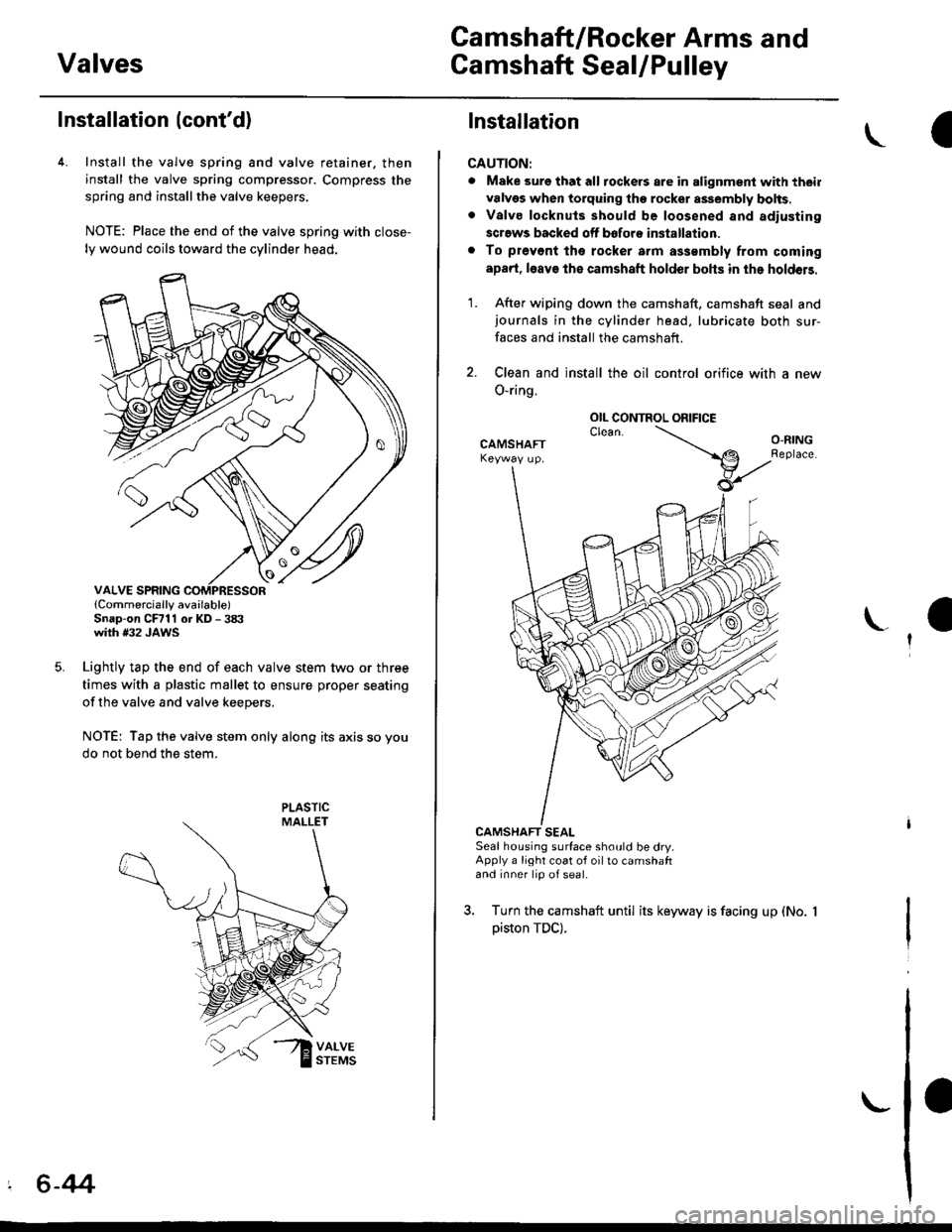
4. Install the valve spring and valve retainer. then
install the valve spring compressor. Compress the
spring and installthe valve keepers.
NOTE: Place the end of the valve spring with close-
ly wound coils toward the cylinder head.
lCornmercially available)Snap-on CFrll or KD - 3tX'with #32 JAWS
Lightly tap the end of each valve stem two or three
times with a plastic mallet to ensure proper seating
of the valve and valve keepers.
NOTE: Tap the valve stem only along its axis so you
do not bend the stem.
' 6-44
Installation
CAUTION:
. Make sure that all tockers are in alignment with their
valvgs when torquing the rocket assembly bolts,. Valve locknuls should be loosened and adiusting
screws backed off bofore installation.
. To prevont tho rocker arm a$smbly from coming
apad, l6av€ the camshaft holder bohs in the holdeB.
1. After wiping down the camshaft, camshaft seal andjournals in the cylinder head, lubricate both sur-
faces and install the camshaft.
2. Clean and install the oil control orifice with a new
O-ring.
CAMSHAFT SEALSeal housing surface should be dry.Apply a light coat of oil to camshaftand inner lip of seal.
3. Turn the camshaft until its keyway is facing up (No.
piston TDC).
OIL CONTROL ORIFICE
Page 181 of 2189
Rocker Arms
Removal
'1. Hold the rocker arms together with a rubber band to
prevent them from separating.
Remove the intake and exhaust rocker shaft oil con-
trol orifices, then remove the VTEC solenoid valve
and the sealing bolts.
NOTE: The shapes ofthe intake and exhaust oil con-
trol orifices are different, ldentify the parts as they
are removed to ensure reinstallation in the original
locauons.
2.
EXHAUST ROCKERSHAFT ORIFICE
INTAKE ROCKERORIFIGEClean.Clean.
O.RINGO.RINGReplace.
RUEBER BAND
Replace. _ (lX
-dJ'v-l-
\
6-71
3. Screw 12 mm bolts into the rocker arm shafts.
Remove each rocker arm set while slowly pulling
out the intake and exhaust rocker arm shafts.
12 mm BOLTS
ROCKER ARM SHAFTS
Page 182 of 2189
Rocker Arms
Disassembly/Reassembly
CAUTION: After installing the rocker shaft oritice, make suro thot the orifics is correctly installed in the hole of rockershaft by trying to turn the rocker shaft. ll the orifice is in place, it should not turn.
NOTE:
. ldentify parts as they are removed to ensure reinstallation in original locations.. Inspect rockershafts and rockerarms (see page6-73).
o Rocker arms must be installed in the same position if reused.. Clean the rocker shaft orifices when installino.
a
I erior. to ,"installing, clean arr the parts in sorvent, dry them, and appry rubricant to any contact surfaces.
y'///
CYLTNDER NUMBER
SEALING BOLTS 20 mm64 N m {6.5 kg{.m, /t7 lbf.ftl
k
r ROCKEN
INTAKE ROCKER ARM ASSEMBLIES