Page 443 of 2189

PGM-FI System
l-Fos3sl
tFos36l
tF1361 l
Fr362-1
tF13sil
Crankshaft Position/Top Dead Center/Cylinder Position (CKP/TDC/CYPI Sensor
f99 - 00 Models except D16Y5 engine with M/T)
The scan tool indicates Diagnostic Trouble Code (DTC) P0335: A malfunction in the Crankshaft Position (CKP)
sensor circuit.
The scan tool indicates Diagnostic Trouble Code (DTC) P0336: A range/performance problem in the Crankshaft
Position (CKP) sensor circuit.
The scan tool indicates Diagnostic Trouble Code (DTC) P1361: Intermittent interruption in the Top Dead Center
{TDC) sensor circuit.
The scan tool indicates Diagnostic Trouble Code {DTC) P1362: No signal in the Top Dead Center (TDC) sensor
circuit.
The scan tool indicates Diagnostic Trouble Code (DTC) P1381: Intermittent interruption in the Cylinder Position(CYP) sensor circuit.
lTiaSt The scan tool indicates Diagnostic Trouble Code (DTC) P1382; No signal in the Cylinder Position (CYP) sensor: circuil.
DoscriDtion
The CKP Sensor determines timing for fuel injection and ignition of each cylinder and also detects engine speed. The TDC
Sensor determines ignition timing at start-up (cranking) and when crank angle is abnormal. The CYP Sensor detects the
position of No. 1 cylinder for sequential fuel injection to each cylinder. The CKP/TDC/CYP Sensor is built into the distribu-
tor.
NOTE; lf DTC P1359 is stored at the same time as DTC P0335, P0336, P1361. P1362, P1381 and/or P1382, troubleshoot DTC
P1359 first, then recheck for those DTCS. D16Y5 engino:
SENSORROTOR
TDGSENSORCKPSENSOBTDCSENSOBCKPSENSOBCYPs€NsonBOTORROTORBOTONROTOR ROTOR
D16Y7, D16Y8 ongine:
(To page 11-175)
1-174
- The MIL has been reportod on.- DTC P0335, P0336. P1361,P1362, P1381 rnd/or P1382.restored.
Problem verific{tion:1. Do the ECM/PCM Reset Proce-dure.2. Start the engine.
Intormittcnt failure, systom b OKat thb time. Check to. poor con-nections or loose wires at C120(dktributorl and ECM/PCM.
ls DTC P0335, P0336, P1361, P1362,P1381 and/or Pl382 indicated?
Check tor an open in the CKP/TDC/CYP 3enior:1. Turn the ignition switch OFF.2. Disconnect the distributor 10Pconnector,3. Measure resistance betweenthe terminals of the indicatedsensor (*see table).
Replrce the distributor ignitionhou3ing (!ee section 231.ls there 350 700 0?
SENSORDTCSENSORTEBMINAIECM/PCMTERI\,4INAICOLOR
CKPP0335
P0336
2c88LU
6c9
TDCP1361
P1362
3c20GRN
7c21BED
CYPP1381
P1342
c29YEL
Ic30BLK
Page 444 of 2189

Dl6Y5.816A2 engine:
DISTRIEUTOR
Terminal side olmale terminals
016Y7, Dt6Y8 engine:
DISTRIBUTOR8P CONNECTOR (Cl201
Terminal side olmale terminals
CKP MIWHT}
lDC M(REDI
ECM/PCM CONNECTORc l31P)
wire side of female terminals
t
l0P coNNECTOR {C120)(From page 11-174)
Chock for.3hort in lho CKP/
Tlrc s6n3o.:
Check {or continuity to body
ground on both tsrminals of the
indicated sensor individuallY.
Chsck for an open in the wile3
ICKP/TIrc line6l:1. R€connect the CKP/TDC son-
sor 4P connector.2. Disconnect the ECM/PCM con-
nector C 131P).3. Measure resistance between
the terminals ol the indicated
sensor on the ECM/PCM con-
nector 1*see tablel.
Ropsir opon in tho indiclted son-ior wiro3 l*!sa tabla).ls there 350 - 700 o?
Chack for a .ho in th6 wiros
{CKP/TDC lino3l:Check for continuity between
body ground and ECM/PCM con-
nector terminals C8, C20 and/or
C29 individually.
Rcpair rhort in th. indicat.d 36n_
lor wirar {'3ac trblol.
Substituto . known-good ECM/
PCM lnd rechock. lf 3ymptom/indicatlon go6s aw.y, ropllc.tho origin.l ECM/PCM.
ECM/PCM CONNECTOR C (31P)
Wire side of femsle terminals
CKP P
11-175
Page 456 of 2189
l,a
Crankshaft Position/Top Dead Center/Cylinder Position (CKP/TDC/CYPI Sensor
Thescantoo|indicatesDiagnosticTroub|ecode(DTc)P1359:Aprob|eminthecrankshaftPosjtion/TopDead
Center/Cvlinder Position (CKP/TDC/CYP) sensor circuit'
- The MIL has been reported on- DTC P1359 is stored
Problem veritication:1. Do the ECM Reset Procedure
2. Stan the engine lftheengine
won't start, crank it for at least
10 seconds-
lntermittent failure, sYstem is OK
Check for poor connecllon3 or
loose wires at C120 {distributor}and ECM,/PCM.
ls DTC P1359 indicated?
Check for poor connections or
loose wires between the distribu
tor and the ECM/PCM
Substitute a known'good ECM/
PCM, and rccheck. lt 3ymPtom/
indication goes awtY, rePlace
the original ECM/PCM.
r ta
11-1A7
Page 680 of 2189

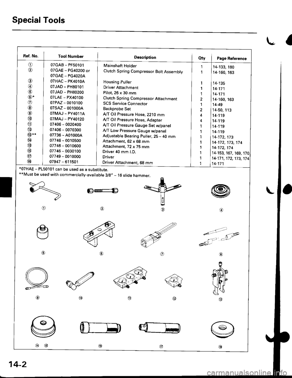
Special Tools
l.- a
Ref. No. Tool Number
o,6'\
€)
@)
@-
@
@
o
@
@
@
@..
@
@
@
@
@
07GAB - PF50101
07GAE - PG40200 or
OTGAE - PG4O2OA
07HAC - PK4010A
07JAD - PH80101
07JAD - PH80200
07LAE - PX40100
07PM - 0010100
07sM - 0010004
OTMAJ - PY4O1 1A
07MAJ - PY40120
07406 - 0020400
07406 - 0070300
07736 - A010004
07746 - 0010500
07746 - 0010600
07746 - 0030100
07749 - 0010000
07947 - 611501
Mainshaft Holder
Clutch Spring Compressor Bolt Assembly
Housing Puller
Driver Attachment
Pilot, 26 x 30 mm
Clutch Spring Compresso. Attachmenr
SCS Service Connector
Backprobe Set
IVT Oil Pressure Hose, 2210 mmAy'T Oil Pressure Hose, Adapter
Ay'T Oil Pressure Gauge Set dpanelA,/T Low Pressure Gauge WpanelAdjustable Bearing Pulter, 25 - 40 mmAftachment, 62 x 68 mm
Aftachment, 72 x 75 mmDriver 40 mm l.D.
Driver
Driver Attachment, 68 mm
I
1
1
1
I
1,l
'l
1
I
1
1
14-133, 180
14-160, 163
14-135
14-171
14-'�t7'l
14-160, 163
14-49
14-50, 113
r4-119
14- 1 19
14-119'14-1 19
14-172,173
14-172,'t73,114
14-172,174
14-153, 167. 169, 170
1+17 1 , 17 2, 173, 17
14-'t7'l
4
w
@o
*07HAE - P150101 can be used as a substitute.**Must be used with commercially-available 3/8,, _ 16 slide
E-E
@
@@
hammer.
=k
lalg
€)
ry
o
e
@
o
----a\\<-t-'- /\26
@@
@@@
aL
14-2
Page 728 of 2189
Troubleshooting Procedures
1.
2.
(cont'dl
Remove the kick panel on the passenger's side {see section 20}.
Remove the PCM. and turn the PCM over.
Inspect the circuit on the PCM according to the troubleshooting flowchart with the spocial tools and a digital multime-ter as shown.
How lo Use tha Backprobe Set
Connect the backprobe adapters to the stacking patch cords, and connect the cords to a multimeter. Using the wireinsulation as a guide for the contoured tip of the backprobe adapter, gently slide the tip into the connector from thewire side until it comes in contact with the terminal end ofthe wire.
BACKPROSE
BACKPROBE SET07saz - (xtl(xtoA
{two required)
DIGITAL MULNMEIER(Comm€rcially 6vailabl€l-aHM-32-003
t..
14-50
or equival€nt
Page 791 of 2189

Road Test
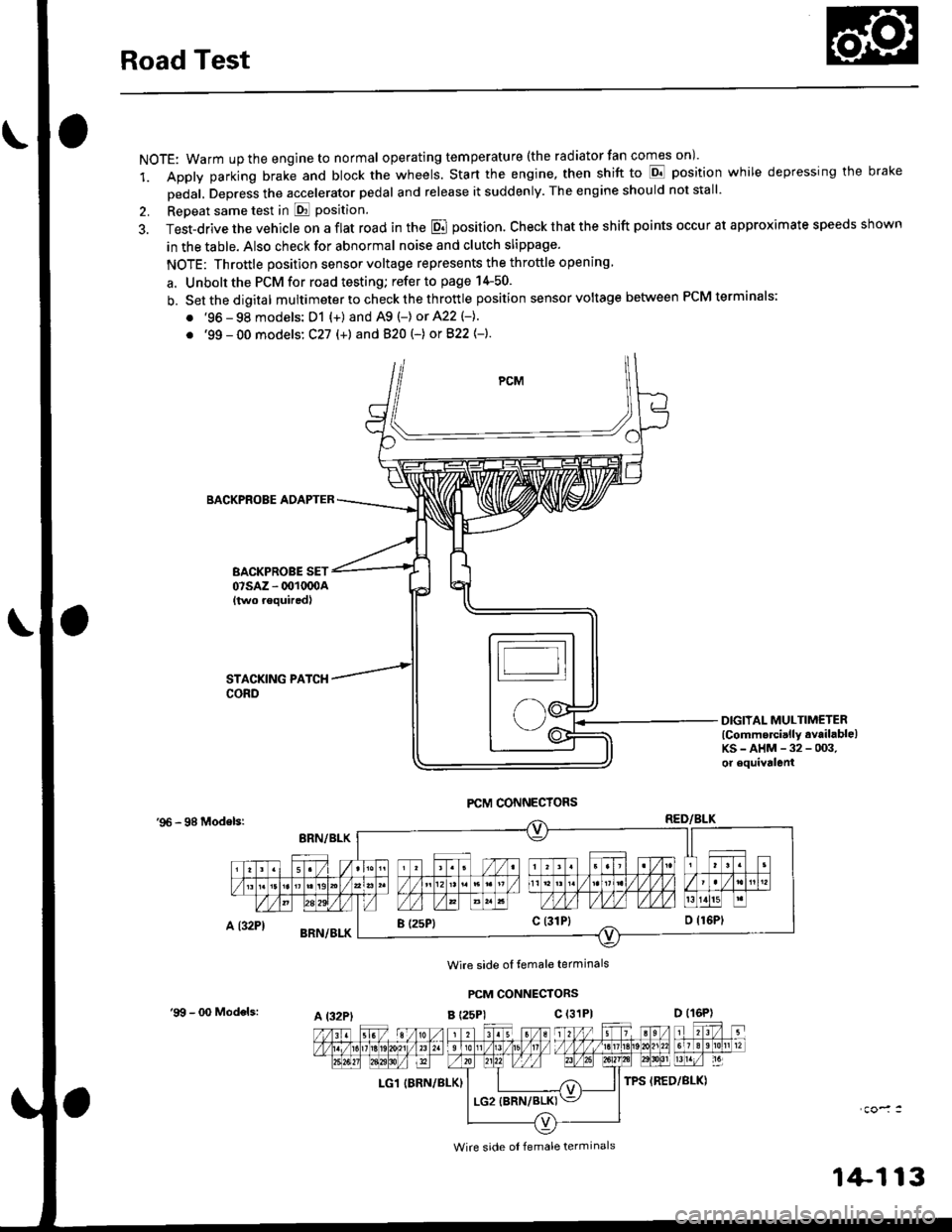
NOTE: Warm up the engine to normal operating tem peratu re (the rad iator fan comes on )'
1. Apply parking brake and block the wheels. Start the engine, then shift to E position while depressing the brake
Dedal, Depress the accelerator pedal and release it suddenly. The engine should not stall'
2. Repeat same test in E Position.
3. Test-drive the vehicle on a flat road in the E position. Check that the shift points occur at approximate speeds shown
in the table. Also check for abnormal noise and clutch slippage.
NOTE: Throttle position sensor voltage represents the throttle opening
a. Unbolt the PCM for road testing; refer to page 14-50.
b. Setthedigital multimeter to check the th rottle position sensor voltage between PCM terminals;
. '96 - 98 models: D1 {+) and A9 (-) or 422 (-}.
. '99 - 00 models: C27 (+) andB20t-) orB22{-}.
BACKPROBE ADAPTER
BACKPROBE SET07sAz - 001oq)A{two requiredl
DIGIIAL MULTIMETERlCommercially available)KS-AHM-32-003,or equivalenl
'96 - 98 Modelsr
Wire side ol temale terminals
PCM CONNECTORS
B t25Pl c (31P)
LG1 IBRN/BLK)
I (25P1c (31P}
A t32PtD (16P)
Wire side ol female terminals
'9!t - 00 Models:
1+113
Page 872 of 2189

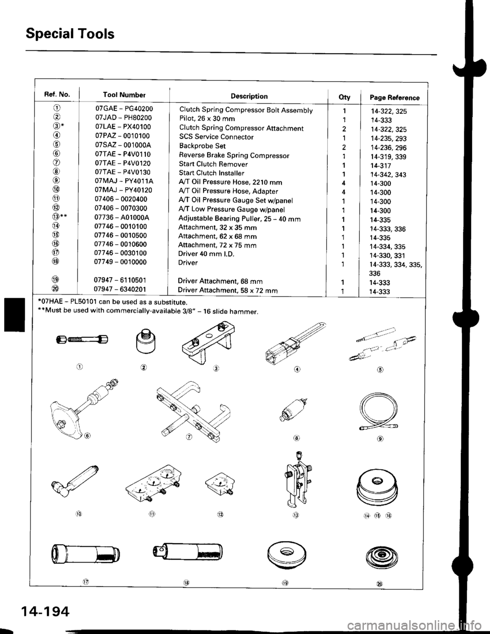
Special Tools
Ref. No. I Tool Number
o
@alr *
@
o
@6l
@
o
@
@-"
@
@
@
o
@
07GAE - PG40200
07JAD - PH80200
07LAE - PX40100
07PM - 0010100
07sM- 0010004
07TAE - P4V01l0
07TAE - P4V0120
07TAE - P4V0130
07 tvlAJ - PY4011A
07MAJ - PY40l20
07406 - 0020400
07406 - 0070300
07736 - A0r 0004
07746 - 0010100
07746 - 0010500
07746 - 0010600
07746 - 0030100
07749 - 0010000
07947 - 6110501
01947 - 6340201
Clutch Spring Compressor Bolt AssemblyPilot. 26 x 30 mm
Clutch Spring Compressor Attachment
SCS Service Connector
Backprobe Set
Reverse Brake Spring Compressor
Stan Clutch Remover
Stan Clutch Installer
A/T Oil Pressure Hose,2210 mmAy'T Oil Pressure Hose, Adapter
Ay'T Oil Pressure cauge Set WpanelAy'T Low Pressure Gauge w/panel
Adjustable Bearing Puller, 25 - 40 mmAttachment, 32 x 35 mm
Attachment, 62 x 68 mm
Attachment, 72 x 75 mm
Driver 40 mm l.D.
Driver
Driver Aftachment, 68 mm
Driver Attachment, 58 x 72 mm
I
1
2
Ia,l
1
1
1,1
1
1'1
I
1
1
't4-322,325
14-333
14-322,325't4-235,293
14-236, 296
r4-319,339't 4-311
14-342,343't4-300
14-300
14-300
14-300
14-335
14-333, 336
14-335
14-334, 335
14-330, 331
14-333, 334, 335,
336
14-333
14-333*07HAE - PL5010l can be used as a substitute.**Must be used with commercially-available 3/8.,- 16 slide hammer.
E*E
o
e
@
>.'.- -t-'- t'\;4
e'o
1:,'Jt*
dAt:-
io(313
@
@
@
@18l
aio
@
IR
L
14-194
Page 883 of 2189

Electronic Gontrol System ('99 - 00 Modelsl
The electronic controt system conststs of a Powertrain control Module (PCM). sensors, three linear solenoids and an
inhibitor solenoid. shifting is electronically controlled under all conditions A Grade Logic control system to control shift-
ing in E position while the vehicle is ascending or descending a slope'
fn"pCVirlocatedbelowthedashboard,underthekickpanelonthepassenger'sside'
The pCM controls the transmassion to reduce engine speed and retain the engine's cooling efficiency when the vehicle is
driven with full throftle acceleration
lf the vehicle is continuously driven at lull throttle acceleration, the PCM regulates the pulley hydraulic pressure to
increase the pulley ratio which. as the result, reduces the engine speed and retains the designed cooling efficiency After
the vehicle has been driven at a lower engine speed for a while, the PCM increases the pulley ratio to the original ratio'
i"i ".nl",rr starting in the E position, the PcM cuts off the ,Vc clutch (if the A/c is on) and increases the engine speed to
900 rpm when the transmission is shifted to the E position'
The start clutch functions to make smooth starting possible. To let the start clutch function properly, the PcM regulates
the start clutch hydraulic pressure based on the engine's negative pressure memorized in the E position'
FCM
s*o.d.ry G..t Sh.h
(cont'd)
14-205