Page 913 of 2189

Troubleshooting Procedures
(cont'd)
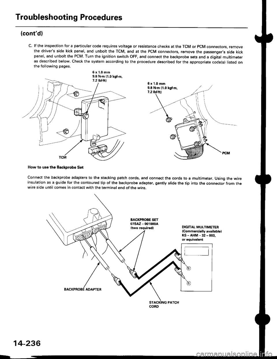
C. lf the inspection for a particular code requires voltage or resistance checks at the TCM or PCM connectors, removethe driver's side kick panel, and unbolt the TCM, and at the PCM connectors, remove the passenger's side kickpanel, and unbolt the PCM. Turn the ignition switch OFF, and connect the backprobe sets and a digital multimeteras described below. Check the system according to the procedure described for the appropriate code(s) listed onthe following pages.
6x1.0mm9.9 N.m {1.0 kgt m,
How to use lhe Backprob€ SE{
Connect the backprobe adapters to the stacking patch cords, and connect the cords to a multimeter, Using the wireinsulation as a guide for the contoured tip of the backprobe adapter, gently slide the tip into the connector from thewire side until comes in contact with the terminal end of the wire.
BACI(PROBE SET07saz - 001 txtoaItwo requirodlDIGITAL MULTIMETER(Commarcially avsibblelKS-AHM-32-(x)3,or oquivalent
6 x 'l,0 mm9.E N.m (1.0 kgf.m,7.2 rbtftt
coRo
14-236
ADAPTER
Page 973 of 2189

Road Test
NOTE: Warm up the engine to normal operating temperature (the radiator fan com6s on).
1. Apply the parking brake and block the wheels. Start the engine, then shift to the E position while depressing the
brake pedal. Depress the accelerator pedal and release it suddenly. The engine should not stall.
2. Test in E position
Park the vehicle in a slope (approx. 16'). apply the parking brake, and shift into E position. Release the brake; the
vehicle should not move.
3. Test-drive the vehicle on a flat road in the position shown in the table. Check that the engine speeds meet the approx-imate vehicle speeds shown in the table.
NOTE: Throttle position sensor voltage represents the throttle opening. To monitor the throttle position sensor volt-age, use one of the following methods:
A. Connect the Honda PGM Tester, and go to the PGM-FI Data List.
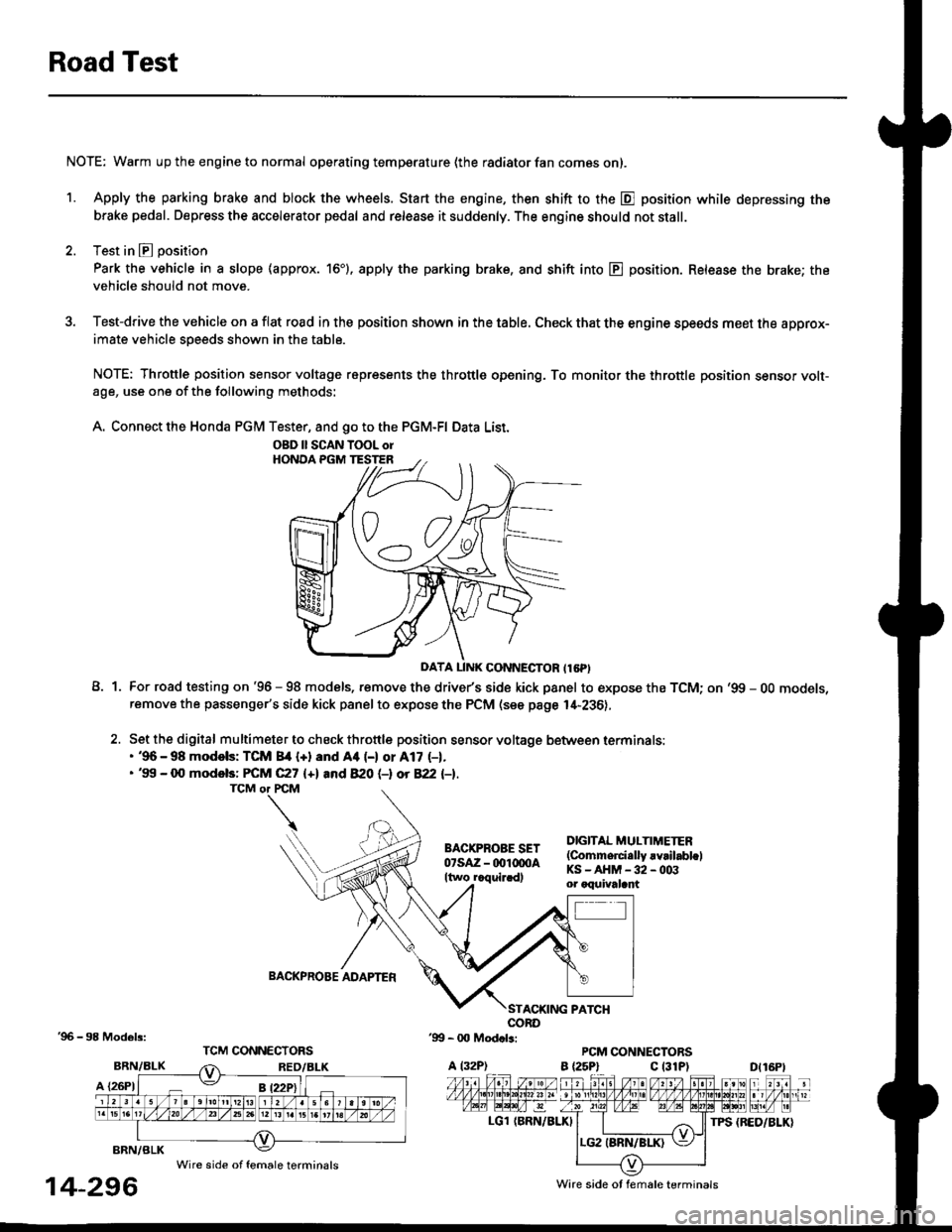
A1For road testing on '96 - 98 models, remove the drive/s side kick panel to expose the TCM; on '99 - OO models,remove the passenger's side kick panel to expose the PCM (see page l,[-236),
Set the digital multimeter to check throttle position sensor voltage between terminals:. '96 - 98 modols: TCM 84 {+} and Aa (-) or A17 (-1.. '99 - 0O models: FCM C27 {+l and 820 (-l ot 822 l-1.
DIGITAL MULTIMETER(Commerci.lly rvrilabl.lKS-AHM-32-003or oquivalant
BACKPROBE ADAPTER
BRN/BLK
A {26P1
TPS {BED/BLK}
'96 - 98 Models:
BRN/BLK
14-296
OBD ll SCAN TOOL orHONOA PGM TESTER
D{16Pt
Ware side ot female terminals
Wire side of female terminals
Page 1077 of 2189

Pressure Control
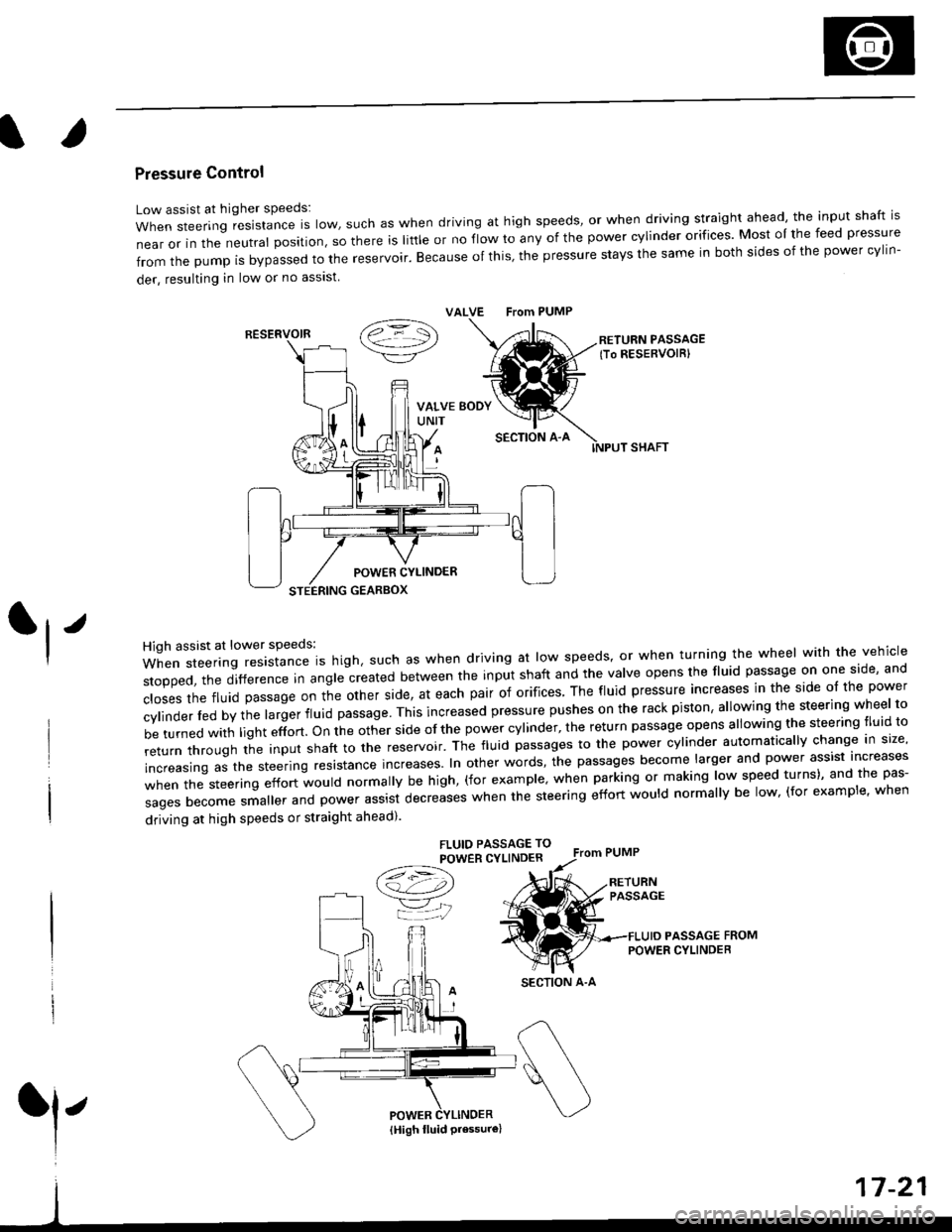
Low assist at higher speeds:
WhensteeringresistanceIsIow,suchaswhendrivingathighspeeds,orwhendrivingstraightahead,theinputshaftis
near or in the neutral position, so there is little or no fiow ro any of the power cylinder orifices. Most oI the feed pressure
fromthepumpisbypassedtothereservoir.Becauseofthis,thepressurestaysthesameinbothsidesofthepowercy||n-
der, resulting in low or no asslst
VALVE From PUMP
SECTION A-A
RETURN PASSAGElTo RESERVOIRI
POWER CYLINDER
STEERING GEARBOX
High assist at lower speeds:
When steering resistance is high. such as when driving at low speeds' or when turning the wheel wirh the vehicle
stopped,thedifference|nang|ecreatedbetweentheinputshaftandtheVa|veopensthef|uidpassageononeside,and
c|osesthefluidpassageontheotherside,ateachpairoforifices'Thef|uidpressureincreasesinthesideo|thepower
cy|inder|edbythe|argerf|uidpassage'Thisincreasedpressurepushesontherackpiston,a|lowingthesteeringwhee|to
be turned with light effort. on the other side of the power cylinder, the return passage opens allowing the steering tluid to
returnthroUghtheinputshafttothereservoir'Thef|uidpassagestothepowercy|inderautomatica||ychangeins|ze,
increasing as the steering resrstance increases. In other words, the passages become larger and power assist increases
when the steering effort would normally be high, (for example' when parking or making low speed turns)' and the pas-
sagesbecomesma||erandpowerassistdecreaseswhenthesteeringeffortwou|dnorma||ybe|ow,(forexamp|e,when
driving at high speeds or straight ahead).
FLUIO PASSAGE TO
POWER CYLINDER
/t=\\a!-4,))
=YjJ
RESERVOIR
SECTION A-A
l'
{High fluid Pressure}
Page 1094 of 2189

Steering Column
Inspection
NOTE: The tilt steering column type is shown; the con-
ventional steering column is similar except for the tilt
mechantsm.
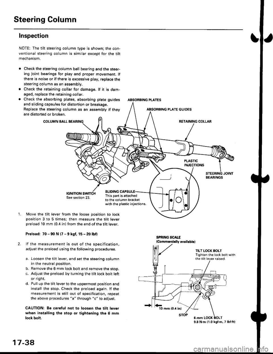
Check the steering column ball bearing and the steer-ing joint bearings for play and proper movement. lf
there is noise or if there is excessive play, replace the
steering column as an assembly.
Check the retaining collar for damage. lf it is dam-
aged, replace the retaining collar.
Check the absorbing plates, absorbing plate
and sliding capsules for distonion or breakage.
Replace the steering column as an assembly
are distorted or broken.
COLUMN BALL
ABSORBING PLATE GUIDES
guides
if they
SLIDING
BEARINGS
TILT LOCK BOLTTighten the lock bolt withthe tilt lever raised.
This part is attachodto the column bracketwith the plastic injections.
1.Move the tilt lever from the loose position to lockposition 3 to 5 times; then measure the tilt leverpreload l0 mm {0.4 in) from the end ofthe tilt lever.
Preload: 70 - 90 N (7 - 9 kgf. 15 - 20 lbf)
lf the measurement is out of the specification,
adjust the pfeload using the following procedures.
a. Loosen the tilt lever, and set the steering column
in the neutral position.
b. Remove the 6 mm lock bolt and remove the stop.
c. Adjust the preload by turning the tilt lock bolt left
or flgnr.
d. Pull up the tilt lever to the uppermost position and
install the stop. Check the preload again. lf the
measurement is still out of specification, repeat
the above procedures "a" through "c" to adjust.
CAUTION: Be caretul not to loosen tho tilt lever
when installing the stop or tightening the 6 mm
lock bolt.
17 3a
10 mm (0.4 inl
9.8 N.m (1.0 kgl.m,7 lbf.ft)
Page 1289 of 2189
Interior Trim
tReplacement
CAUTION:
. Put on gloves to protect your hands.
o When prying with a flat-tip screwdriver, wrap it with protective tape to prevent damage.
NOTE: Take care not to bend or scratch the trim and panels.
4D:
>: Clip locationsa>,2c >,2'lo >,2E >,2
r*'" n t-lt't
\wi, i
' l ll/
_tr* @,
CENTER PILLARUPPER TRIMREAR PILLARTRIM
LOCK CYLINDER TRIM
tl'
I
E'vBELT UPPERANCHOR(see page 20-85)
Disconnect thehigh mount brakelrght connector.
T SIDE TRIMRemove the rear seat cushion and rearseat side bolster lsee page 20-19]'.
)
lnstallation is the reverse of the removal procedure.
NOTE:
. lf necessary, replace any damaged clips.. Before installing the front seat belt upper anchor
and rear shelf. make sure there are no twists or
kinks in the seat belts.(cont'd)
B>,6
REAR SHELF
k"si
fEFT KICKPANEL
20-59
Page 1290 of 2189
lnterior Trim
Replacement (cont'dl
3D:
>: Clip locationsA>,2CLIP
N;
nt-.l I'"'\R
I
")!
F >, lil
TRIM
B>,3
G >,2H>,2
t
FRONT SEATBELT UPPEBANCHORlsee page 20 86)
SIDE TRIM PANELPROTECTOR
LEFT KICKPANEL
c >,8o>,3
PIVOT BRACKET
{see page 20-80)
lnstallation is the reverse of the removal procedure
NOTE:
. lf necessary, replace any damaged clips'
. Before installing the anchor bolts, make sure there
are no tlvists or kinks in the seat belts'
E >,8
>: Screw, bolt locationsA>,3 8>,6
^l l-lEF\
#, A@ Y
*"0
c>, 1
I "4"
\s
o >,2
l@@
\---
s,4, ffi;T
FRONT PILLARB
eV
REAR SIDESHELF
SIDE TRIMPANELRemove the rear seat-back and
rear seat cushion (see Page 20_80)
Disconnect the rear speaker
connector (both sides,
for some models).
REAR TRIMPANEL
q
RIGHT KICKPANEL
"x-
20-60
Page 1291 of 2189
Il
2Di
>: Clip locationsa>,28>,3
CLIP
G>,4H >,2
D >,3>i Screw location3.4
REAR SHELF
SIOE TRIM PANELRemove the rear seat-back andrear seat cushaon (see page20-a1l.
,
Disconnect the highmount brake light
SEAT BELT
€'
/>"RIGHT KICKPANEL
)
TRIM
nJ'.'rI\ZI
1\f-
F>,8
N 4'dr
SIDE TRIM
LOWER ANCHOR(see page 20-86)
c>, 14E>,2
Installation is the reverse of the removal procedure.
NOTE:
. lf necessary, replace any damaged clips.
. Before installing the anchor bolts and rear shelf,
make sure there are no twists or kinks in the seat
belts.
FRONT PILLAR
FRONT SEATBELT UPPERANCHOR
v
.h,'t6d
\
LEFT KICKPANEL
20-61
Page 1426 of 2189
Special Tools
Bef. No. Tool NumberDescriptionQty I Page Reference
o
@
*07JGG - 00l0l0A
07sAz - 0010004
07947 - 6340300
07965 - 6920500
Belt Tension Gauge
Backprobe Set
Driver Attachment
Hub Assembly Gulde Attachment
1
'1
1
22-43
22-14,16
22-34
22-35' Included in the Belt Tension cauge Set, 07TGG-0010004.
a6r
L
3r
22-2