1996 HONDA CIVIC Elect
[x] Cancel search: ElectPage 1818 of 2189
How To Use This Manual
The next few pages describe how this manual is organized. They also
explain what kind of information the manual contains, what that
informalion means, and how to use it to troubleshoot electrical problems.
Circuit schematics break the entire electrical system into individual
systems, like the Low Fuel lndicator Light on the nelit page.
Only electrical components that work together are shown together,
so you won't be distracted by unrelated wires.
Explanations of the abbreviations and svmbols used in the schematics
begin on page [Fl. You'll need to know what they mean before you can use
a schematic effectively.
Page 1828 of 2189
Five-Step Troubleshooting
L Verify The Complaint
Turn on all the components in the problem
circuil lo check the accuracy of the customer
complaint. Note the symptoms. Do not begin
disassembly or testing until you have
narrowed down the problem area.
2. Analyze The Schematic
Look up the schematic for the problem
circuit. Determine how the circuit is
supposed to work by tracing the current
paths lrom the power source through the
circuit components to ground. Also, trace
circuits that share wiring with the problem
circuit. The names of circuits that share the
same fuse, ground, or switch, and so on, are
referred to in each circuit schematic. Try to
operate any shared circuits you didn't check
in step 1 . lt the shared circuits work, the
shared wiring is OK, and the cause must be
in the wiring used only by the problem
circuit. lf several circuits fail at the same
time, the fuse or ground is a likely cause.
Based on the symptoms and your
understanding of the circuit's operation,
identify one or more possible causes.
3. lsolate The Problem By Testing The Circuit
Make circuit tests to check the diagnosis
you made in step 2. Keep in mind that a
logical, simple procedure is the key to
efficient troubleshooting. Test for the most
likely cause of failure first. Try to make tests
at points that are easily accessible.
4. Fix The Problem
Once the specific problem is identified,
make the repair. Be sure to use proper tools
and safe procedures.
5. Make Sure The Circuit Works
Turn on all components in the repaired
circuit in all modes to make sure you've
fixed the entire problem. ll the problem was
a blown fuse, be sure to test all of the
circuits on that fuse. Make sure no new
problems turn up and the original problem
does not recur.
Test Equipment
Most circuits include solid-state devices.
Test the voltages in these circuits only with
a 1o-megaohm or higher impedance digital
mUltimeter. Never use a test light or analog
meter on circuits that contain solid-state
devices. Damage to the devices may result.
Test Light and DVOM
On circuits without solid-state devices, use a
test light to check for voltage. A test light is
made up of a 12 volt bulb with a pair of leads
attached. After grounding one lead, touch the
other lead to various points along the circuit
where voltage should be present. The bulb
will go on if there is voltage at the point being
tested. lf you need to know how much
voltage is present, use a digital
volVohmmeter (DVOM).
Self-Powered Test Light and DVOM
Use a self-powered test light to check for
continuity. This tool is made up of a light bulb,
battery, and tlvo leads. To test it, touch the
leads together: the light should go on.
Use a self-powered test light only on an
unoowered circuit. First, disconnect the
battery, or remove the fuse that feeds the
circuit you are working on. Select two points
in the circuit belween which you want to
check continuity. Connecl one lead of the
self-powered test light to each point. lf there
is continuity, the test light's circuit will be
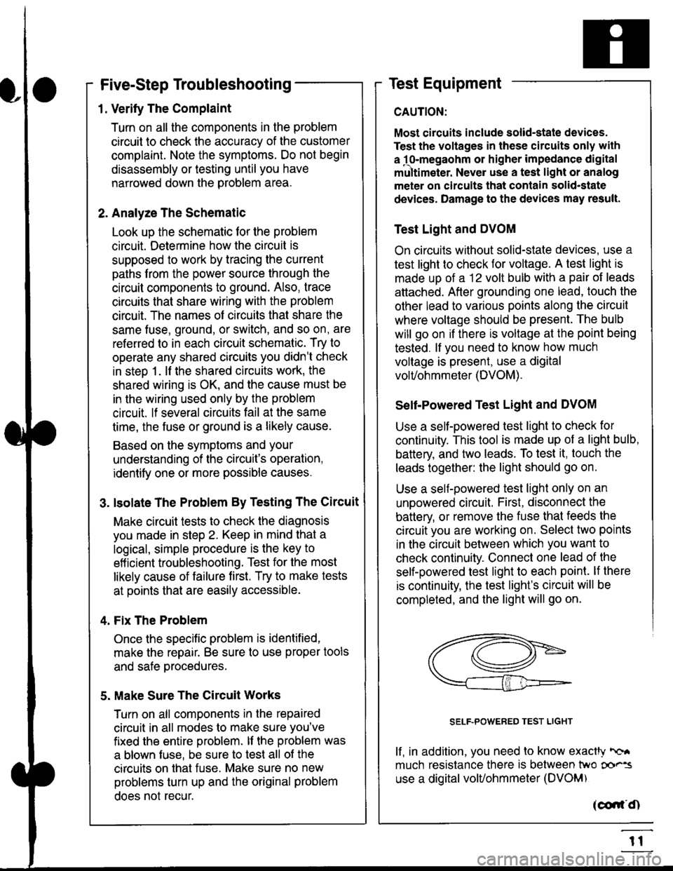
completed, and the light will go on.
SELF-POWERED TEST LIGHT
lf, in addition, you need lo know exacW hc'.
much resistance there is between two oo'^=
use a digital volUohmmeter (DVOM)
acdrt'Cn
t1
Page 1829 of 2189
In the "OHMS" range, the DVOM will measure
resistance between two points along a circuit.
Low resistance means good continuity.
Diodes and solid-state devices in a circuit can
make a DVOM give a false reading. To check
a reading, reverse the leads, and take a
second reading. lf the readings differ, the
component is affecting lhe measurement.
Jumper Wire
Use a jumper wire to bypass an open circuit.
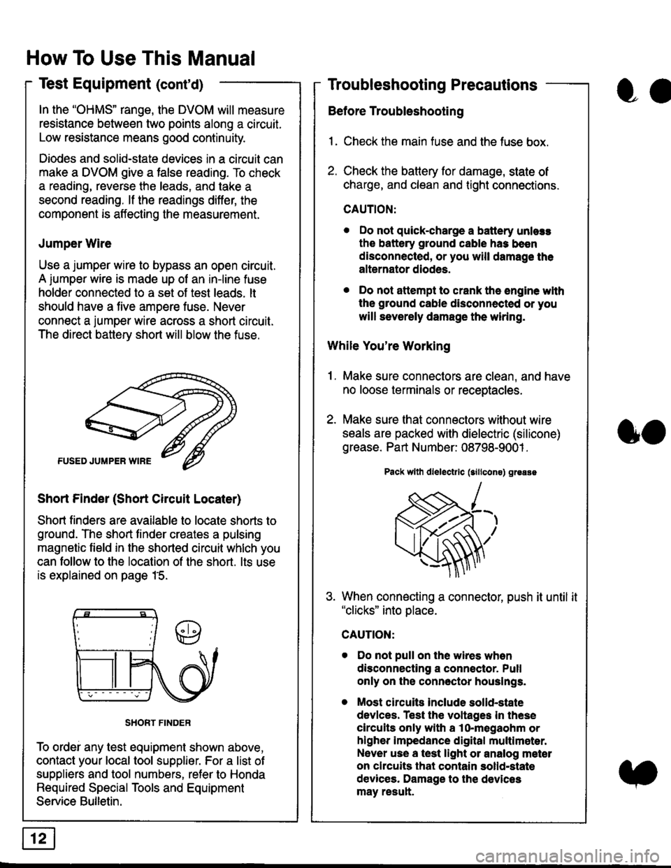
A iumper wire is made up ot an in-line fuse
holder connected to a set of test leads. lt
should have a five amoere fuse. Never
connect a jumper wire across a short circuit.
The direct battery short will blow the fuse.
Short Finder (Short Circuit Locater)
Short finders are available to locale shorts to
ground. The short tinder creates a pulsing
magnetic field in the shorted circuit whlch you
can follow to the location of the short. lts use
is explained on page 15.
SHORT FINDER
To ordei any test equipment shown above,
contact your local tool supplier. For a list of
suppliers and tool numbers, refer to Honda
Required Special Tools and Equipment
Service Bulletin.
How To Use This Manual
Test Equipment (cont'd)
oa
Troubleshooting Precautions
Before Troubleshooting
1. Check the main fuse and the fuse box.
2. Check the battery for damage, state of
charge, and clean and tight connections.
CAUTION:
. Do not quick-charge a battery unlers
the battery ground cable has been
disconnected, or you will damage the
alternator diodes.
. Do not attempt to crank the engine wlth
the ground cable disconnected or you
will severely damage the wiring.
While You're Working
1. Make sure connectors are clean, and have
no loose terminals or receptacles.
2. Make sure lhat connectors without wire
seals are packed with dielectric (silicone)
grease. Part Number: 08798-9001 .
Pack wllh dlelectrlc (sillcons) greass
When connecting a connector, push it until it"clicks" into place.
Do not pull on the wires when
disconnecting a connector. Pull
only on the connector houslngs.
Most circuits Include solid-state
devlces. Test the voltages In these
circuits only with a lo-megaohm or
higher impedance digital multlm6ter.
Never use a test light or analog meter
on chcuits that contain solld-state
devices. Damage to the devices
may result.
oo
Page 1830 of 2189
Troubleshooting Tests
Testing for Voltage
When testing for voltage at a connector
without wire seals, you do not have to
seoarate the two halves of the connector.
Instead, probe the connector from the back.
Always check both sides of the connector
because dirty, corroded, and bent terminals
can cause problems (no electrical contact =
an open).
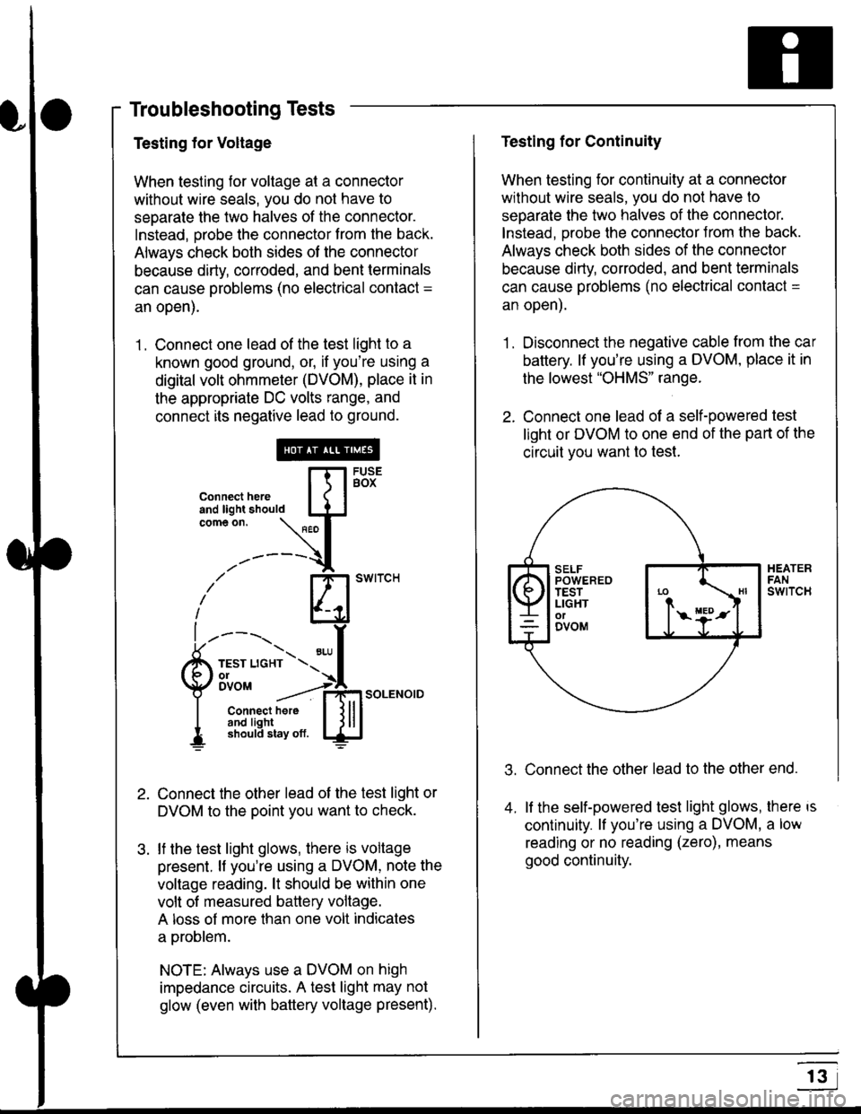
1 . Connect one lead of the test light to a
known good ground, or, if you're using a
digital volt ohmmeter (DVOM), place it in
the appropriate DC volts range, and
connect its negative lead to ground.
Connect the other lead of the test light or
DVOM to the point you want to check.
lf the test light glows, there is voltage
present. lf you're using a DVOM, note the
voltage reading. lt should be within one
volt of measured battery voltage.
A loss of more than one volt indicates
a problem.
NOTE: Always use a DVOM on high
impedance circuits. A test light may not
glow (even with baftery voltage present).
connecthere [fl5tst-tand light should IJJcomeon.
\" I
------{
/' BT swrrcH
lhl
l ----., I
6m""*soLENo,DI connect here I { lll
I 3#Ji8iL,* lj!!J
Testing for Continuity
When testing for continuity at a connector
without wire seals, you do not have to
separate the two halves of the connector.
lnstead. Drobe the connector Jrom the back.
Always check both sides of the connector
because dirty, conoded, and bent terminals
can cause problems (no electrical contacl =
an open).
1. Disconnect the negative cable from the car
battery. lf you're using a DVOM, place it in
the lowest "OHMS" range.
2. Connect one lead of a self-powered test
light or DVOM to one end of the part of the
circuit vou want lo test.
Connect the other lead to the other end.
lf the self-powered test light glows, there is
continuity. lf you're using a DVOM, a low
reading or no reading (zero), means
good continuity.
.t.
A
r3
Page 1842 of 2189
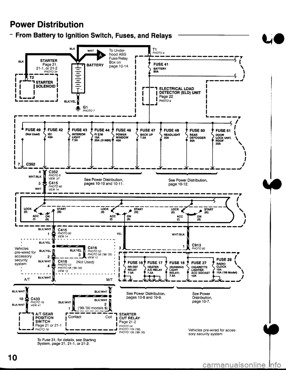
Power Distribution
- From Battery to lgnition Switch, Fuses, and Relays
STARTERPage 21,21-1, ot 21-2
.d1.ro"rr" i
I lsoLENorD I
FUSE 42tG1
BATTERY
To UndeFhood ABSFuse/RelayBox onpage 10-14.
FUSE 47EACK UP
T1
FUSE 41AATTEiY&A
I OETECTOR (ELD) UNIT
tii::.':
UO
PHOfO U
,
I
I
I
t.------J
ELECTRICAL LOAD
i--i rL---- J ELKml
!" Gl
FUSE 4e
0ro{ Urod)FUSE '13Ir|]EAtOAUGHT?.:ta
FUSE 46POWEaWll'IDOW
FUSE /t4
r| E/M1{rA204 (DrGa5)
FUS€ 48TtEADL|a}fT9|'A
FUSE 50NEAAOEFOCGER304
+------, f| ',
I ruse sr I oooa I
J LOC|( uNrr \
il-.4WHT/BLK
Itr '\
\
I
I
I
c352
vlEW 27
c415Se€ Pow€r Distribution,pag6s 10-10 and 10-11.See Power Distribution,page 10-12.
I
\
L------BLK/VI/HT
1
--------Jc415
Vehiclespre-wired foraccessorysecuritysystem
c913PHOTO 6A
FUSE 16AR DEFFEIAY
FUSE 17HEATEA!'/C FEIAY
FUSE 18{RUNNINOL|GHlFET.AY)7.54
FUSE 27CIGAFETTEL|oHTEAACC SOCKET ta
arse ra fBADIO \
?o?"* \15A ('94 raodcr)
ff".acc0)
llL--------J
See Power Distribution,pages 10-8 and 10-9.
STARTERCUT RELAYPage 21-2
P/lolo 135 (99 00)
See PowetDistribution,page 10-7.
Vehicles pre-wired for acces-sory security system
To Fuse 3'|, for delails, see StartrnqSystem, page 21,21-1 , ot 21-2. -
10
Page 1875 of 2189
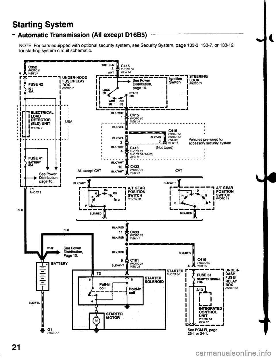
- Automatic Transmission (All except Dl685)
NOTE: For cars equipped with optional security system, see Security System, page 133-3, .133-7, or 133-12
for starting system circuit schomatic.
Starting System
c3s2PHO|O IvlEw 27
ftxiE "2E1404
WHT/BLK
I
lta":
c415
=-mF,Uf.
--l
9,lLT i ld;f,,"-
I
I
It
I
I
I
I
I
I
I
I
pag€ 10.
slan?(ll)
c415
I
Ji.I ELECTRICALI roAoI DETECTOR
I Gt ol ulra Ptfifo I
IJ
BLKAIVHT1
ELK./YEL
au(|vEL
BL'(4I/HT
4
c416PHOTO 53
c4t 6PHO|O 53PHO|O 56 f98 '�oo)vtEw t2
c433
Vehiclss pre-wired foraccessory securaty system(Not Used)
R'SE 4IlA??tNY,olALXAVHY'10
Allsxcsptow aLKlvHrcwSoe Pow6r IDistibution, !page 10. a- ----JT1PHOTO 9
BATTERY
BLKAVHT
7
L-----L---JBLKFED
13:;-1ifl;ft?R
!-
)2 'lPHoto tg
a
BLI(RED
1I
ELIVBED
ALKNED
c433PHOTO 76
Soe PowrDslributbn,Pa€o 10.
9 a c101
er.xiwxr I ffo,rtfl'�t
c4rIPHO|O 63
Ft gg 3r5? F En 3E ^r7.94
4
r'STARTERPHO|O 34UNDER.DASHFUSE/RELAYBOX
A13
tl
II{TEGRATEDco|{TnoLUT{ITPHOfOUvtEw 67,--==--J
Sso PGM-FI, page&1 ot 24-1.
21
lGl
Page 1876 of 2189
![HONDA CIVIC 1996 6.G Workshop Manual - Automatic Transmission (D1685)
c352
vtEw27
FUSE 42tGtao
.I ELECTRICALI LOADr DETECIOn
| (ELD) uNtrI PHOTO 9
I
UNDER.HOOOFUSE/RELAYBOX
r=-----L-_-_-_-_-_-=_-_-Tl.*1"","1#"Ei]""
li F 3,"j,[,ul
WHT/BL HONDA CIVIC 1996 6.G Workshop Manual - Automatic Transmission (D1685)
c352
vtEw27
FUSE 42tGtao
.I ELECTRICALI LOADr DETECIOn
| (ELD) uNtrI PHOTO 9
I
UNDER.HOOOFUSE/RELAYBOX
r=-----L-_-_-_-_-_-=_-_-Tl.*1"","1#"Ei]""
li F 3,"j,[,ul
WHT/BL](/manual-img/13/6068/w960_6068-1875.png)
- Automatic Transmission (D1685)
c352
vtEw27
FUSE 42tGtao
.I ELECTRICALI LOADr DETECIOn
| (ELD) uNtrI PHOTO 9
I
UNDER.HOOOFUSE/RELAYBOX
r=-----L-_-_-_-_-_-=_-_-Tl.*1"","1#"Ei]""
li F 3,"j,[',ul
WHT/BLK
. J 9,1'3.WHt a V|EW 14
tcx,^ ) Page 10'
PHOTO 76
1--*---''!N"t- \o3bz7
See PowerDistribution,page 10.
c433
ALKRED4
r-^==.1
Stadorcontrol
POWERTRAINCONTROLMODULE (PCM)
c101
vtEw 28
ll
"'{----1iLi.' | |
Li-gl{l======i---i
"i*-iIr-m'
:il
See PowerDistribdion,Page '10.
".u,"if---'
-,*! s#;:{"
BLKAVHT N V/EW a t
STARTERCUTFELAYPHO|O 129
(99100)
A"/T GEARPOStTtONswrTcH
See PGlr-Fl,page 25.
STARTER
c419
FUSE 31STAffER Src{AI7.54
UNDER-DASHFUSE/NELAYBOX
BLKREO
11
"'-";;tr
A't 3
BATTERY
21-1
Page 1877 of 2189
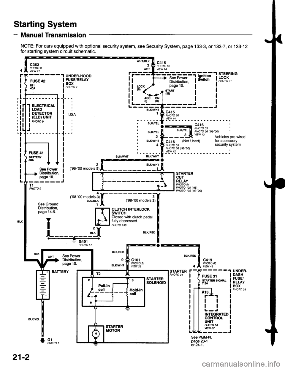
- Manual Transmission
NOTE: For cars equipped with optional security system, see Security System, page 133-3, or 133-7, or 133-12
for starting system circuit schematic.
Starting System
c3s2PHOTA 8vtEw 27
WHT/BLKc415
FUSE 42to!a0a
UNDER-HOODFUSE/RELAYBOXI
I
I
_l
IELECTBICALIOADDETECTOR(ELO) UN|TPtloro I
Sae Po'/Y€rDislibution,pag€ 10.------JT1
Se6 GroundDislribution,page 14-6.
BATTERY
STARTERCUTRELAY
PHO|A 129198)PllO|O r35 f99 00)
a
BLK/FED
9
BLKAVHT
ct01
vlEW 2A
c4't9
vtEw 49
FUSE 31STAATER SICIIAL7.5A
STARTER
4
Sse PGM-FI,page 231ot 2+1.
UNDER-DASHFUSE/RELAYBOX
At3
tl
tl
INTEGRATEDcol{tRoLut{llPHO|O U
r.------T-------------=;-*^:-lsrEERtNG
I i 1'----> R*.|?xf: iiiliffi' t"t%?I,,I Distribulion.1j;cx y' page 10.(0)
it-jtr'tl i
j
r---_-_€rx^,:jF;f
;-;:.==:t A r,+lo'tii:,J?"""
;--;*;.-f -- ^.:---.---1--
,'rr-'OO .o0"," 3,rffiEj,
---;;;;i[
cLUrcH TNTERLOCK tClosed wrlh clutch pedal Ifully depressed. llPHoro 1ra I"**"
!
Se€ PowerDistibution,page 10.
4('98100 models 3)ALU/BLK
f2 lE--r.---?q_l srAFrEn
21-2
I- G1