1996 HONDA CIVIC Elect
[x] Cancel search: ElectPage 1986 of 2189
Front WiperMasher (cont'd)
- How the Circuit Works
When the ignition switch is in ON (ll) or START (lll),
battery voltage is applied to lhe combination wiper
switch. and the windshield wiDer motor.
Low Speed
When you turn the wiper switch to LO, the wiper
motor's low speed winding is grounded through the
BLU wire and the LO speed contacts of the wip€r
switch at G401, and the wipers run at low speed.
ParUOfl
When you turn the wiper switch OFF, the integrated
control unit (PARK input) grounds the wiper motor
through the BLUMHT wire. The cam switch on the
motor signals the integrated control unit that the
wipers are in the PARK position; the control unit
then removes ground from the motor, and the
wipers stop in the PARK position.
High Speed
When the wiper switch is in Hl, the high speed
windings of the windshield wiper motor are
grounded through the BLUIrEL wire and the Hl
contacts of the wiper switch at G401, and the
wipers run at high speed.
Intermittent
When the wiper switch is in lNT, battery voltage is
applied through the YEUBLU wire to the integrated
control unit (lntermittent wiper ON input). The
integrated control unit (lnt€rmittenvPark Wiper
Control) grounds the low speed windings of the
wiper motor and the wipers make a single sweep
every few seconds (See Low Speed above). When
the wiper retums to the PARK position, the park
switch applies battery voltage through the
BLUMHT wire to the integrated control unit (PARK
input), and the wipers stop in the PARK position.
Mist
When you pull the wiper switch down to MIST
position, the high speed windings ot the wiper motor
are grounded through the BLU^/EL wire and the
closed contacts ot the mist switch at G401, and the
wipers make one pass across the windshield at high
speed. The ParUOff function then takes over and
the wipers stop in the PARK position.
Washel
When you pull the wiper switch toward you to turn
on the washer switch, battery vollage is applied to
the washer motor. The motor pumps fluid onto the
windshield until you release the lever; on '98r99
models, the integrated control unit (windshield
washer ON input) s€nses power at the WHT/BLK
wire terminal and runs the wipers whenever the
washer motor runs.
Refer lo the Service Manual (Seclion 23, Electrical)
for specific tests or troubleshooting procedures.
91-2
Page 2006 of 2189
Headlights (cont'd)
- How the Circuit Works
Low Beams
With the headlight switch in HEAD and the dimmer
switch in LO, current tlows through the headlight
switch. fuse 21 . fuse 22. and the low beam
tilaments to ground, and the low beams come on.
High Beams
With the headlight switch in HEAD and the dimmer
switch in Hl, current flows through the headlight
switch, dimmer switch, fuses 4, 5, and the high
beam filaments to ground, and the high beams
come on.
Current also llows through the high beam indicator
light to ground. The high beam indicator comes on
to remind the driver that the high beams are on.
Flash-to-Pass
The flash feature works with the headlight switch in
OFF, PARK, or HEAD (low beams). When you move
the flash-to-pass switch to ON, current flows
through the switch, fuses 4 and 5, and the high
beam filaments to ground, and the high beams
flash. The high beam indicator also flashes during
the flash operation. The flash function has no effect
if the high beams are already on
Daytime Running Lights (Canada)
When you turn the ignition to ON (ll) with the
parking brake released, the daytime running lights
control unit supplies battery voltage at the
WHT/RED wire. This voltage is applied to the high
beam headlights through the daytime running lights
resistor. Each high beam headlight receives less
than battery voltage causing them to come on at
reduced brightness.
lf the parking brake is set, a ground signal is applied
to the daytime running lights control unit at the
RED/GRN wire. lf the parking brake is set when you
first turn the ignition switch to ON (ll), the high beam
headlights will remain off until you release the
parking brake. Once the high beam headlights are
on, setting the parking brake will not turn them ofi.
When low or high beam operation is requested,
battery voltage from the headlight switch is applied
to the daytime running light control unit via the RED
wire. The daytime running lights control unit then
turns off the headlights.
Refer to the Service Manual (Section 23, Electrical)
for specific tests or lroubleshootrng procedures.
110-14
Page 2018 of 2189
Power Windows (contd)
- How the Circuit Works
CAUTION: You could iniure your arms, hands, or
fingers if you unintentionally switch the driver's
window to "automatic down" while working in
that door with the power on. Disconnect the
window switch conneclot or the battery when
working in the driver's door.
System Description
The operation of the power windows is controlled by
the main switch in the power window master switch.
When the main switch is in OFF, only the driver's door
window can be opened or closed. With the main
switch ON, all windows can be ooened or closed
either by swtches in the master panel, or swttches in
the doors. The driver's window switch also has an
automatic down mode which is tumed on by pushing
the switch down to its second oosition.
The power windows are driven by reversible motors.
Each motor is protect€d by a built-in circuit breaker.
lf the window switch is held on too long (with the
window obstructed, or after the window is fully up or
down), the circuit breaker opens the circuit. The
circuit breaker resets automaticallv as it cools.
Driver's Window
With the ignition switch in ON, voltage is provided to
the coil of the power window relay through fus€ 24.
The contacts of the power window relay close, and
voltage is applied to the driver's switch. When you
push the power window master switch to UP, voltage
is applied to the driver's window motor. (The motor's
ground path is back through the master power
window switch.) The driver's window motor then
drives the window up. When you push the switch to
DOWN, voltage is applied in the opposite direction
and the motor drives the window down.
Automatic Down (Driver's Window)
With the ignition switch in ON or START, voltage is
applied to the coil of the power window relay. The
contacts of the power window relay close and
voltage is applied lo the power window master
switch. When you push the driveas switch to the
AUTO DOWN position, voltage is applied through
the driver's switch to the driver's window motor. The
control unit receives pulses at the pulser input while
the motor is running. When the window is fully
down, the motor stops, and pulses are no longer
generated by the pulser. This is sensed by the
control unit at the pulser input, and voltage is no
longer applied to the driver's window motor.
Passenger Windows
With the ignition switch in ON, voltage is applied to
the coil of the power window relay through fuse 24.
The contacts of the power window relay then close,
applying voltage to the individual window switches
and the power window master switch. With the
master panel main switch ON, the passenger
windows can be ooerated from the individual
window switches or from tho master panel switches.
When you push the front passengsr's window
switch to UP, voltage is applied to the f ront
passenger's window motor. (The motor is grounded
through the contacts in the front passenger's
window switch and the oower window master
switch.) The window moves up as long as you hold
the switch in the UP position. lf you push the switch
to DOWN, voltage is applied in th€ opposite
direction to the front passenger's window motor, and
the window movss down as long as you hold the
switch in the DOWN Dosition. The window switches
in the other doors operate similarly.
When you push the front passenger's switch in the
master panel to UP, voltage is applied through the
front passenger's window switch contacts to the
front passengefs window motor. (The motor is
grounded through the contacts in the front
passenger's window switch and the power window
master switch.) The window moves up as long as
you hold the switch in the UP position. lf you push
the switch to DOWN, voltage is applied in the
opposite direction to lhe front passenger's window
motor, and the window moves down as long as you
hold the switch in the DOWN position. The other
passenger window switches in the master panel
operate similarly.
Refer to the Service Manual (Section 23, Electrical)
for specific tests or troubleshooting procedures.
120-4
Page 2021 of 2189
Moonroof (cont'd)
- How the Circuit Works
Moonroof Open
When you push the moonroof switch to the OPEN
position, the moonroof open switch applies ground
to the moonroof "open" relay through the YEL wire.
The moonroof "open" relay applies battery voltage
to the moonroof motor through the GRN/RED wire.
The moonroof "close" relay supplies ground to the
moonroof motor through its normally closed relay
conlacls. When the moonroof moves out of the fully
closed oosition. the tilvclose switch moves to the
OPEN position; the open/close switch moves to the
OPEN oosition.
Moonrool Tilt
When you push the moonroof switch to the TILT
position, the moonroot tilt switch applies ground to
the moonroof "close" relay through the BLU wire,
tilvclose switch and RED wire. The moonroof"close" relay applies battery voltage to the
GRNff EL wire to the moonroof motor. The
moonroof "open" relay supplies ground to the
moonroof motor through its normally closed relay
contacts. When the moonroof is in the tilt oosition,
the trlvclose switch moves to the TILTED position;
the open/close switch moves to the TILTED
Dosition.
Moonroof Close trom the Open Position
When you push the moonroof switch to the CLOSE
position, the moonroof "close" switch applies ground
to the moonroof "close" relay through the YEURED
wire, tilvclose switch and GRN/RED.wire. The
moonroof "close" relay applies battery voltage to the
GRNI/EL wire to the moonroof motor. The
moonroof "open" relay suppfies ground to the
moonroof motor through its normally closed relay
contacts. When the moonroof is fully closed, the
tilvclose switch moves to the closed position; the
open/close switch moves to the CLOSED position.
122-2
Moonroot Close from the Tilt Position
When you push the moonroof switch to the CLOSE
posilion, the moonroof "open" switch applies ground
to the moonroof "close" relay through the YEURED
wire, open/close switch and moonroof "open" relay.
The moonroof "open" relay applies battery voltage to
the moonroof motor through the GRN/RED wire. The
moonroof "close" relay supplies ground to the
moonroof motor through its normally closed relay
contacts. When the moonroof is fully closed, the
tilvclose switch moves to the closed oosition and the
open/close switch moves to the CLOSED position.
Refer to the Service Manual (Section 23, Electrical)
for specific tests or troubleshooting procedures.
Page 2057 of 2189
Ir
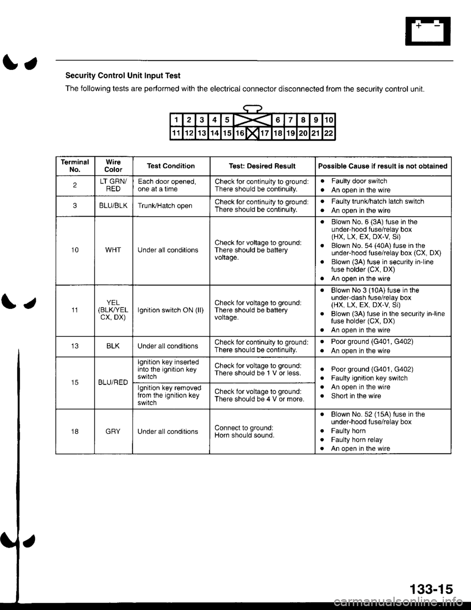
Security Control Unit Input Test
The following tests are performed with the electrical conneclor disconnected from the security control unit.
\;
12345X67I910
1112131415rol171819202122
TerminalNo.WireColorTest ConditionTest: Desired ResultPossible Cause il result is not obtained
2LT GRN/REDEach door opened,one at a timeCheck for conlinuity to ground:
There should be continuity.
Faulty door switch
An open in the wirea
3BLU/BLKTrunUHatch openCheck for continuity to ground:
There should be continuity.
aFaulty trunldhatch latch switch
An open in the wirea
10WHTUnder all conditionsCheck tor voltage to ground:
There should be batteryvoltage.
. Blown No. 6 (3A) fuse in theunder-hood fuse/relay box(HX, LX, EX, DX-V Si)
. Blown No. 54 (40A) fuse in theunder-hood fuse/relay box (CX, DX)
. Blown (3A) fuse in security in-linefuse holder (CX, DX)
. An open in the wire
11YEL(BLK/YEL
cx, DX)lgnition switch ON (ll)Check for voltage to ground:
There should be batteryvoltage.
. Blown No 3 (10A) fuse in theunder-dash tuse/relay box(HX, LX, EX, DX.V, Si)
. Blown (3A) fuse in the security in-linefuse holder (CX, DX)
. An open in the wire
BLKUnder all conditionsCheck for continuity to ground:
There should be continuity.
aPoor ground (G401, G402)
An open in the wirea
t5BLU/RED
lgnition key insertedinto the ignition keyswitch
Check for voltage to ground:
There should be 1 V or less.aPoor ground (G401, G402)
Faulty ignition key switch
An open in the wire
Short in the wire
a
a
algnition key removedfrom the ignition keyswitch
Check for voltage to ground:
There should be 4 V or more.
18GRYUnder all conditionsConnect to ground:
Horn should sound.
. Blown No.52 (15A) luse in theunder-hood luse/relay box
. Faulty horn
. Faulty horn relay
. An open in the wire
133-15
Page 2058 of 2189
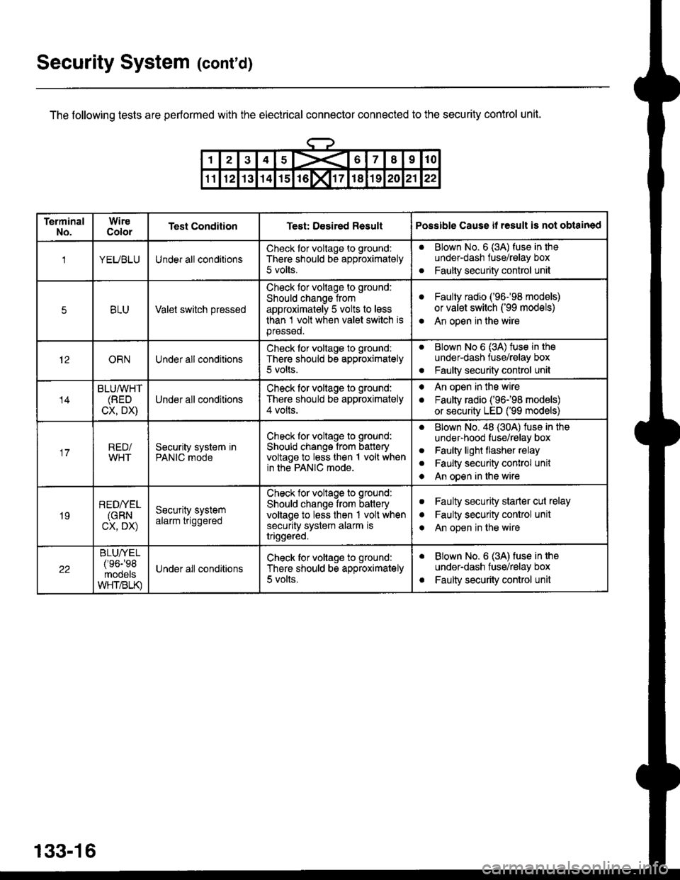
Security System (cont'd)
The following tests are performed with the electrical connector connected to the security control unit.
133-16
TerminalNo.WireColorTest ConditionTest: Desired ResultPossible Cause il result is not obtained
1YEUBLUUnder all conditionsCheck tor voltage to ground:
There should be approximately
5 volts.
aBlown No. 6 (3A) fuse in theunder-dash fuse/relay box
Faulty security control unita
5BLUValet switch pressed
Check tor voltage to ground:
Should change from
approximately 5 volts to less
than 1 volt when valet switch isprsssed.
aFaulty radio ('96-98 models)
or valet switch ('99 models)
An open in the wirea
12ORNUnder all conditionsCheck for voltage to ground:
There should be approximately5 volts.
aBlown No 6 (3A) tuse in tho
under-dash tuse/relay box
Faulty security control unito
14
BLU/WHT(BED
CX, DX)Under all conditions
Check for voltage to ground:
There should be approximately4 volts.
. An open in the wire
. Faulty radio ('96198 models)
or security LED ('99 models)
17RED/WHTSecurity system inPANIC mode
Check for voltage to ground:
Should change from batteryvoltage to less then 1 volt whenin the PANIC mode.
aBlown No. 48 (30A) luse in the
under-hood fuse/relay box
Faulty light flasher relay
Faulty security conlrol unit
An open in the wire
a
a
a
19
REDI/EL(GRN
cx, DX)
Security systemalarm triggered
Check tor voltags to ground:
Should change from batteryvoltage to less then 1 volt whensecurity system alarm istriggsred.
aFaulty security starler cut relay
Faulty security control unit
An open in the wire
I
a
22
BLUA/EL/'oa-'oq
mooelsWHT/BLK)
Under all conditionsCheck tor voltage to ground:
There should be approximately
5 volts.
aBlown No. 6 (3A) fuse in the
under-dash fuse/relay box
Faulty security control unita
Page 2075 of 2189
How the Circuit Works
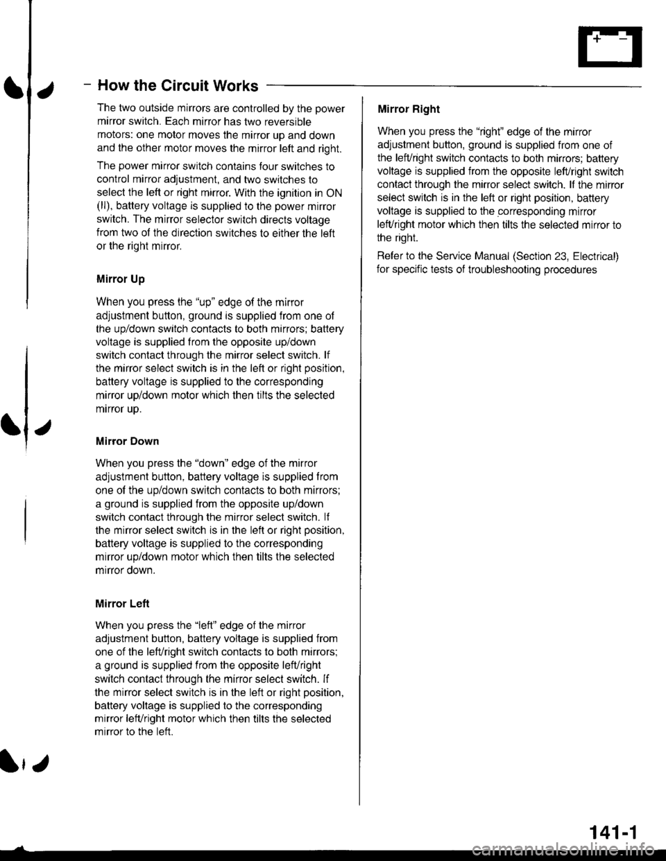
The two outside mirrors are controlled by the power
mirror switch. Each mirror has two reversible
motors: one motor moves the mirror up and down
and the other motor moves the mirror lett and right.
The power mirror switch contains four switches to
control mirror adjustment, and two switches to
select the left or right mirror With the ignition in ON
(ll), battery voltage is supplied to the power mirror
swrtch. The mirror selector switch directs voltage
from two of the direction switches to either the left
or the right mirror.
Mirror Up
When you press the "up" edge of the mirror
adjustment button, ground is supplied from one of
the up/down switch contacts to both mirrors; battery
voltage is supplied from the opposite up/down
switch contact through the mirror select switch. lf
the mirror select switch is in the left or right position,
battery voltage is supplied to the corresponding
mirror uo/down motor which then tilts the selected
mtrror uD.
Mirror Down
When you press the "down" edge of the mirror
adjustment button, battery voltage is supplied Irom
one of the up/down swilch contacts to both mirrors;
a ground is supplied from the opposite up/down
switch contact through the mirror select switch. lf
the mirror select switch is in the left or right position,
battery voltage is supplied to the corresponding
mirror up/down motor which then tilts the selected
mrrror oown.
Mirror Left
When you press the "|eft" edge of the mirror
adjustment button, battery voltage is supplied from
one of the lefuright switch contacts to both mirrors;
a ground is supplied from the opposite lefuright
switch contact through the mirror select switch. lf
the mirror select switch is in the left or right position,
battery voltage is supplied to the corresponding
mirror lefvright motor which then tilts the selected
mirror to the lett.
Mirror Right
When you press the "right" edge of the mirror
adjustment button, ground is supplied from one of
the lefvright switch contacts to both mirrors; battery
voltage is supplied from the opposite left/right switch
contact through the mirror select switch. lf the mirror
select switch is in the left or right position, battery
voltage is supplied to the corresponding mirror
lefuright motor which then tilts the selected mirror to
the right.
Refer to the Service Manual (Section 23, Electrical)
for speclfic tests of troubleshooting procedures
141-1
Page 2076 of 2189
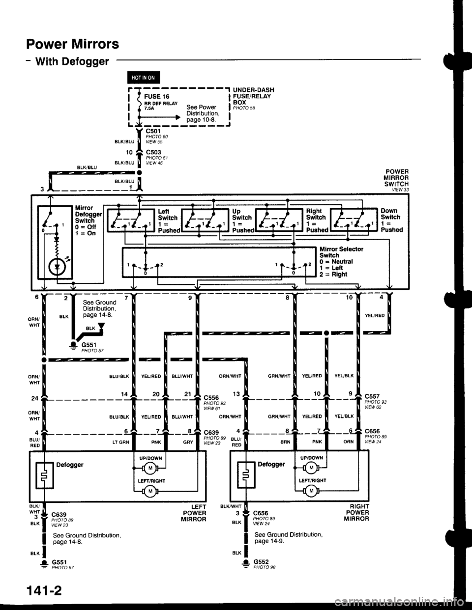
Power Mirrors
- With Defogger
ORN/
i I ;;;
- - - - - -
I HJ.o.',8.3.f;,"
i )tlf*"'*" geePower if,g}"",
!-,i::-i4tir-J
f 9;%.,BLKBLU I V'EW55
'o l9,;%,,BL(/B!U I V/EW 46
a
T'|[
aaa
OFN/
24
ORN/
BLU/RED
--
YEL/FED
20
--
BLUA!/HT
21cs56
OBN/WHf
c639 4
vtEw23 FEO
c557
vlEw 62
c656
ORN
BLK/
BLK
LEFT BLKryVHTPOWER 3MTRROR BLK
".* |..- Gs52
".^ |... G551
c639
vlEw2i
See Ground Distribution,page 14-8.
c656
vlEw 24
See Ground Dislribution,page 14-9.
Minor Selecto.SwitchO = Neutral1 = Lelt2 = Rlght
',41-2