Page 965 of 2189
Electrical Troubleshooting ('99 - 00 Models)
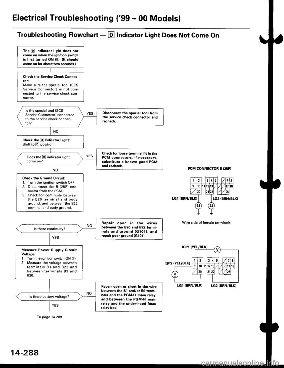
Troubleshooting Flowchart - El Indicator Light Does Not Come On
PCM CONNECTOR B I25PI
LGl {BRN/BLK)
Wire side ot female terminals
LGlIARN/BLK) LG2IBRN/BLKI
The D indicator light does notcome on whon ths ignhion switchis tirst turned ON {lll. llt shouldcome on tor about two s€conds.)
Check the Service Check Connec-tor:Make sure the special tool {SCSService Connectorl is not connected to the service check con-nector,
ls the special tool (SCS
Service Connectorl connectedto the service check connec-tor?
Disconnect the sp€cial tool f]omthe seruice chcck connoclor andaecheck.
Check the E Indicalor Light:Shift to E posjtion.
Check tor loose te.minal fit in thePCM connectors, lf nocessary,substitute a known-good PCMand aecheck.
Does the E indicator light
Check the Ground Circuit:1. Turn the ignition switch OFF.2. Disconnect the B (25P) connector from the PCM.3. Check tor continuity betweenthe 820 terminal and bodyground, and between the 822terminal and body ground.
Fepair open in th. wirosb€tw.en the 820 end 822 termi-nals and ground {G1011, !ndrepair poor ground {G1011.
ls there continuity?
Measure Power Supply CircuitVoltage:1. Turn the ignitlon switch ON (ll).
2. Measure the voltage betweenterminals Bl and 822 andbetween terminals B9 and820.
Ropair op€n or short in tho wireb€tween the Bl and/or B!| tarmi-nds and the PGM-FI main .ohy,and between tho PGM-FI mainrelay and the under-hood fuso/r€lav box.
ls there battery voltage?
To page 14-289
14-2AA
Page 967 of 2189
ElectricalTroubleshooting ('gg - 00 Models)
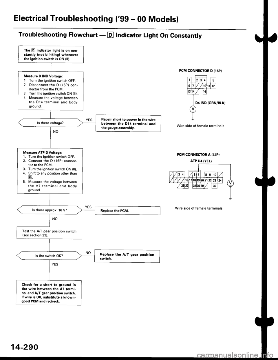
Troubleshooting Flowchart - E Indicator Light On Constantly
FCM CONNCCTOR D tl6PI
23I5
61t012
tsll / rc
II D4 rND
o
(GRN/BLK)
Wire side of female terminals
rcM CONNECTOR A I32PI
ATP Dil {YELI
Wire side of lemale terminals
The E indicator light is on con-stantly {not blinkingl wheneverthe ignition switch is ON lll|.
Mersure D IND Voltage:1. Turn the ignition switch OFF.2. Disconnect the D (16P) con-nector from the PCM.3. Turn the ignition switch ON (ll).4. Measure the voltage betweenthe 014 terminal and bodyground,
Repair short to power in tho wirebstween the Dl4 termin.l sndthe gaug€ r3sembly.
Measure ATP DVoltage:1. Turn the ignition switch OFF.2. Connect the D (16Pi connec-tor to the PCM.3. Turn the ignition switch ON lll).4. Shift to any position other thanE,5. lMeasure the voltage betweenthe 47 terminal and bodyground.
ls there approx. 10 V?
Test the A/T gear position switch{see section 23).
Check for a shorl lo ground inthe wire between tho A7 termi-nal and A/T ge.r polition switch.l, wire is OK, substitute a known-good PCM and recheck.
14-290
Page 970 of 2189
Start Clutch Control@
T
Start Clutch Calibration Procedure
NOTE: When the following parts are replaced, the TCM
must memorize the feedback signal for the start clutch
control.
. TCM
. Transmissionassembly
. Stan clutch assembly
. Lower valve bodv assembly
. Engine assembly or overhaul
'96 Model Only
CAUTION: Do not uso this procsdure on'97 - (X) mod-
els or you will damage the transmission. On '97 - 00
models, the TCM or PCM memorizes ths loodback sig'
nals when you drive the vehicle.
1. Engage the parking brake, and block the front
wheels securely.
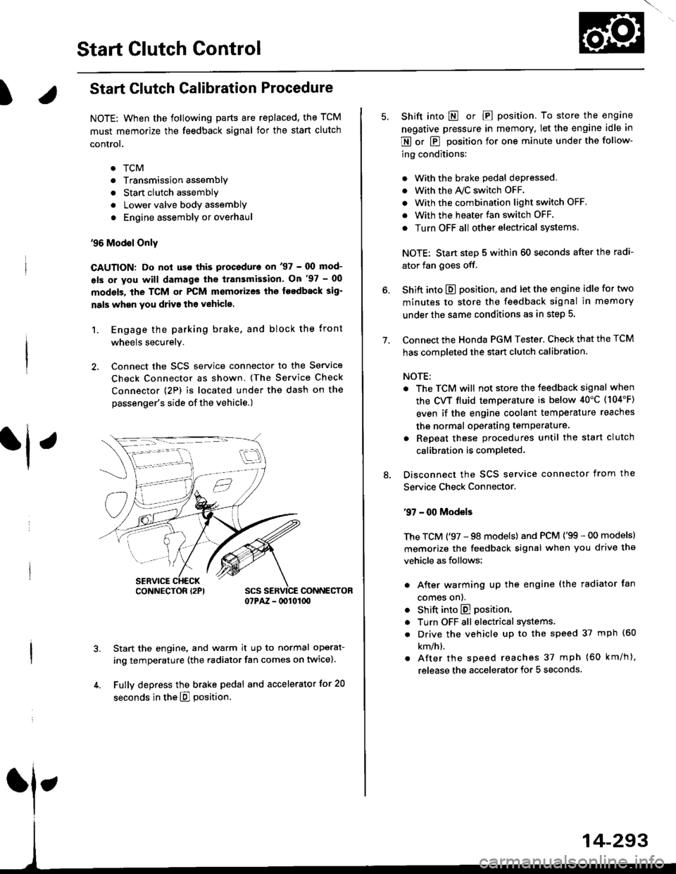
2. Connect the SCS service connector to the Service
Check Connector as shown. (The Service Check
connector (2P) is located under the dash on the
passenger's side of the vehicle.)
CONNECTOR07PAZ - lDl01(xt
Start the engine, and warm it up to normal operat-
ing temperature (the radiator fan comes on twice).
Fully depress the brake pedal and accelerator for 20
seconds in the E] position.
rl ,
CONNECTOR I2PI
14-293
7.
Shift into E o|. E position. To store the engine
negative pressure in memory. Iet the engine idle in
E or E position for one minute under the follow-
ing conditions:
. With the brake pedal depressed,
. with the y'\/c switch oFF.
. With the combination light switch OFF.
. With the heater fan switch OFF.
. Turn OFF all other electrical systems
NOTE: Start step 5 within 60 seconds after the radi-
ator fan goes off.
Shift into E position, and let the engine idle for two
minutes to store the feedback signal in memory
under the same conditions as in step 5.
Connect the Honda PGM Tester. Check that the TCM
has completed the start clutch calibration.
NOTE:
. The TCM will not store the feedback signal when
the CVT fluid temperature is below 40"C (104'F)
even if the engine coolant temperature reaches
the normal operating temperature.
. Repeat these procedures until the start clutch
calibration is completed-
Disconnect the SCS service connector from the
Service Check Connector.
'97 - 00 Models
The TCM ('97 - 98 models) and PCM ('99 - 00 models)
memorize the feedback signal when you drive the
vehicle as follows:
. After warming up the engine (the radiator fan
comes onl.
. Shift into E position.
. Turn OFF all electrical systems,
. Drive the vehicle up to the speed 37 mph (60
km/h).
. After the speed reaches 37 mph (60 km/h),
release the accelerator for 5 seconds.
Page 988 of 2189
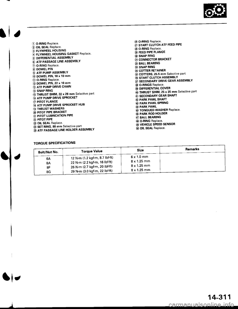
C O-RING Replace.
e) OIL SEAL RePlace.' FLYWHEEL HOUSING
O flVWneel }|OUSttttG GASKET Replace
6 DIFFERENTTALASSEMELY
@ lrr plsslce uruE ASSEMBLY
O O-RING Replace
@ DOWEL PIN
€) ATF PUMP ASSEMBLY(O DowEL PlN, 18 x 10 mm
O O-RING Replace.o DowEL PlN, 22 x 10 mm
lrr puup oRve cxltttt
iA SNAP RING
f3 fxaUst St|t|l, zz t 28 mm Selective part
Gt lrr punp ontve spaocxer
O PITOT FLANGE
ito nTF purrap ontve SPRoGKET HUB
(O THRUST WASHERS
@ PITOT PIPE BRACKET
O PITOT LUBRICATION PIPE
@ PITOT PIPEt3 OIL SEAL Replace.
Oa SEt AtitC, SO mm Selective Part
o3 lrr passlce ltnE HoLOER ASSEMBLY
6) o-RING Replace.
€) START CLUTCH ATF FEED PIPE
CO O-RING Replace.
€I FEEO PIPE FLANGE
@ SNAP RING
O' CONNECTOR BRACKET
@ BALL BEARING
6} SNAP RING64 COTTER RETAINER6D CoTTERS,25.5 mm selective Part6t stlnt cLutcH asseMsLv
@ secoruomv ontvE GEAR ASSEMBLY
@ o-RINGS Replace
6) DIFFERENTIAL COVER
rO ttaUSr SntU, zs t 35 mm Selective part
@ SECONDARY GEAR SHAFT
@ PARK PAWL SHAFT
@ PARK PAWL SPRING.1i PARK PAWL
@ TONGUED WASHER REPIACE,
@ PARK ROO HOLDER
@ BALL BEARING
@ o-RING Replace.
@ VEHICLE SPEED SENSOR
@ OIL SEAL Replace.
ft,
)
TOROUE SPECIFICATIONS
6x1.0mm
8 x 1.25 mm
8 x 1.25 mm
8 x 1.25 mm
12 N.m (1.2 kgnm,8.7 lbf'ft)
22 N.m (2.2 kgf'm. 16lbf'ft)
26 N.m (2.7 kgf'm, 20 lbf'ft)
29 N.m {3.0 kgf'm, 22 lbift)
14-311
Page 990 of 2189

6) TRANSMISSION HOUSING GASKET Replace'
@ DOWEL PIN
@) ATF FEED PIPE
@ o-RING Replace.
60 o-RING Replace.
@) DRIVE PULLEY SPEED SENSOR
@ TRANSMISSION HANGER
@ SNAP RING
@ txaust Sxtfu, zs t 31 mm selective part
@ SALL BEARING
6J RING GEAR6D SNAP RING
@ aevense aRlxe rND PLATE Selective part
@ REVERSE BRAKE DISC
@ REVERSE BRAKE PLATE
@ DISC SPRING6} THNUST WASHER
@} finusr NeeoLr eelnNc
@ THRUST WASHER
@ GARRIER ASSEMBLY
@ THRUST WASHER
@ THRUST NEEDLE BEARING
@} SUN GEAR
@ SEALING RING REPIACE'
@ NEEDLE BEARING
@ INPUT SHAFT
@ NEEDLE BEARING
@ SEALING RING FEPIACE'
@ SEALING RING {RUBBERI Replace'
@ ATF FEED PIPE
O END COVER
O ATF FEED PIPE
O DOWEL PIN
@ O-RING Replace.G) FEED PIPE FLANGE
@ reeo ppe ruruce puru
O] ROLLERO IruTENMEDNTE XOUSING ASSEMBLY
ao corutnoL sxlrr lsseugLv
@ tnlrusmtsstottt ttoustt'tc
@ SHIFT CABLE BRACKET
c) BREATHER CAP
@ oll- SEAL Replace.
@ CONTROL LEVER
G LoCK WASHER Replace.(D secololaY ceaR SHAFT SPEED sENsoR
o) onvel put-uv sPEED SENSOR
@ O-RING Replace.(O SNAP RING6 rnmrsutsstoru xouslNc oRlvEN PULLEY
SHAFT ROLLER BEARING
@ END COVER GASKET REPIACE'
@ o-RING Replace
6o mnruulL vnLVe goDY LINE A
64 MANUAL VALVE BODY LINE B
@ O-RING Replace.
@ DETENT SPRING
O ATF FEED PIPE
@ O-RING Replace.
@ MANUAL VALVE EODY
@ DOWEL PIN
@ r'rllull valve goDY SEPARAToR PLATE
6D SNAP RING
@t roRwlno cturcx ASSEMBLY
@ o-RING Replace
@ SNAP RINGo3 spnlruc aetlrupn/RETURN SPRING ASSEMBLY
@ nevense ennr eBtottt
@ o-RING Feplace.
@ SNAP RING RE'AINER
@ ATF FEED PIPE
.1,
TOROUE SPECIFICATIONS
6x1.0mm
6x1.0mm
8 x 1.25 mm
8 x 1.25 mm
8 x 1.25 mm
12 N.m (1.2 kgf'm,8.7 lbf'ft)
14 N.m {1.4 kgf'm, 10 lbift)
37 N.m (3.8 kgf'm, 27 lbf'ft)
26 N.m (2.7 kgf'm,20 lbf'ft)
29 N.m (3.0 kgf'm, 22 lbf'ft)
6B
8B
8F
8G
14-313
rl,
Page 993 of 2189
Transmission Housing/Flywheel Housing
Removal
NOTE:
. Cleanall parts thoroughly in solvent or carburetor cleaner, and dry with compressed air.. Blow out all passages.
. When removing the transmission housing/flywheel housing, replace the following:- O-rings- Secondary drive gear assembly- Sta rt clutch assemblv- Flywheel housing gasket
ATF PASSAGE LINEHOLD€R ASSEMBLY
IX)WEL PIN
OIFFERENTIAL ASSEMBLY
SNAP RING
COTTER RETAINER
COTTERS, 25.5 mmSelective part
8 x 125 mm BOLT
O.RINGRsplaco.
VWHEEL HOUSING
EYWIIEEL HOUSING GASKETRoolace.
START CLUTCHASSEMBLYReplace.
ATF PA$gAGEUNE ASSEMBLY
6 x 1,0 mm BOLT
O.RINGReplace.
ATF PUMP DRIVE CHAIN
SNAP RING
THRUST SHIM,25x35mmSeloctive part
SECONDARYGEAR SHAFT
SECONDARY DRIVEGEAR ASSEMBLYReplace.
PARKPAWL SHAFT
THRUST SHIM, 22 r 28 mmSeloctive partGRII{GSReplac€.6 x 1.0 mm BOIT
ATF PUMP DRIVESPROCKET
PfTOT FLANGE
ATF PUMP DRTVESPROC|(ET HUB
THRUST WASHERS
PARK PAWLSPRING
INPUT SHAFT
14-316
DRIVEN PULLEY SHAFT
InANSMISS|O]{ HOUSTNG
Page 995 of 2189
End Cover/lntermediate Housing
Removal
NOTE:
. Cleanall parts in solvent or carburetor cleansr, and drywith compressed air,. Blow out all passages.
. When removing the end cover/intermediate housing, replacs the following parts:- O-rings- End cover gasket- Transmission housing gasket- Sealing rings- Sealing washers
8 x 1 .25 mm BOLT
REVERSE BRAKE
{u
END PLATE
6 x 1.0 mm BOLT
Dtsc
PLATE
DISC SPRING
SNAP
THRUST
END COVERGASXETFeplac€.25x31 mmSelective part
RING GEAR
THRUST WASHER
THRUSI NEEDLEBEARING
THRUST WASHER
CARRIER ASSEMBLY
THRUST WASHER
THRUST NEEDLEBEARING
SUN GEAR
INPUT SHAFT
SNAP RING
CLUTCH ENDPLATE
sNAP /R|NG I
8 x 1.25 mm BOLT
TRANSMISSTONHOUSING GASKETReplace.
DOWEL PIN
INIERMEDIATEHOUSING ASSEMSLY
FORWARD CLUTCHASSEMBLY
SEALING RING (RUBBER}
Replace.
SNAP RING
o.BINGReplace.
SNAP RINGRETAINER
SPRING RETAINER/RETURN SPRINGS
14-318
HOUSING
Page 1004 of 2189
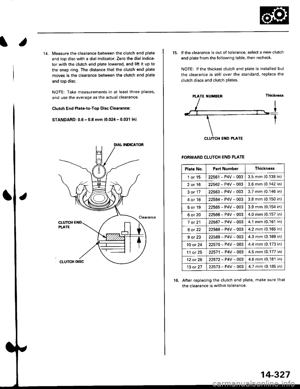
14. Measure the clearance between the clutch end plate
and toD disc with a dial indicator, Zero th€ dial indica-
tor with the clutch end plate lowered, and lift it up to
the snap ring. The distance that the clutch end plate
moves is the clearance between the clutch end plate
and toD disc.
NOTE: Take measurements in at least three places,
and use the average as the actual clearance.
Clutch End Plate-to-Top Disc Clesranc€:
STANDARD: 0.6 - 0.8 mm 10.024 - 0.031 inl
15. It the clearance is out of tolerance, select a new ciutch
end plate from the following table, then recheck.
NOIE: lf ihe thickest clutch end plate is installed but
the clearance is still over the standard, replace the
clutch discs and clutch Plates.
FORWARD CLUTCH END PLATE
After replacing the clutch end plate, make sure thal
the clearance is within tolerance.
16.
PTATE I{UMBEN
Plate No.Part NumberThickn€ss
1or1522561 - P4V - 0033.5 mm (0.138 in)
2or1622562 - P4V -OO33.6 mm (0.142 in)
3or1722563-P4V-0033.7 mm (0.146 in)
4or1822564 - P4V - 0033.8 mm (0.150 in)
5or192256s-P4V-0033.9 mm (0.154 in)
6ot2022566-P4V-0034.0 mm (0.157 in)
7 ot 2122567 -P4V -0034.1 mm (0.161 in)
8ot2222568-P4V-0034.2 mm (0.165 in)
9ot2322569-P4V-0034.3 mm {0.169 in)
10 or 2422570-P4V -OO34.4 mm (0.173 in)
'll or 2522571,P4V-0034.5 mm (0.177 in)
12 ot 2622572-P4V-OO34.6 mm (0.181 in)
13 ot 2722573-P4V -OO34.7 mm {0.185 in)
14-327