Page 712 of 2189

Description
Lock-up System (cont'd)
TOROUE CONVERTER
In B.rl position, in 3rd and 4th, and lDl_- position in 3rd.pressurized fluid is drajned from the back of the torqueconverter through a fluid passage. causing the lock-uppiston to be held against the torque convener cover. Asthis takes place, the mainshaft rotates at the same speedas the engine crankshaft, Together with the hydrauliccontrol, the PCM optimized the timing of the lock_upsystem. Under certain conditions, the lock_up clutch isapplied during deceleration, in 3rd and 4th gear.
The lock-up system controls the range of lock_up accord_ing to lock-up control solenoid valves A and B. and thelinear solenoid. When lock-up control solenoid valves Aand B activate, modulator pressure changes. Lock_upcontrol solenoid valves A and B and the linear solenoidare mounted on the outside of the torque converterhousing. and are controlled by the pclvl.
Lock-up Conditions/Lock-up Control Solenoid Valves/Linear Solenoid Pressure
MODULATOR PRESSURE
.-- LINEAR SOLENOID PRESSURE
LOCK.UP CONTROL. VALVE
LOCK.UP CONTROLSOLENOID VALVELock-up
Conditions
Lock-up Control
Solenoid ValveLineal
Solenoid
PressureAB
Lock-up OFFOFFOFFHig h
Lock-up. HalfONDuty operation
OFF - ON
Lock-up. FullONONHigh
Lock-up
during
decelerationONDuty operation
OFF * ONLowTOROUE CONVERTERCHECI( VALVE
RELIEF VAI-VE
LOCK.UP TIMINGVALVE
^ r______rr r cooLER RELTEF VALVE
t'-
14-34
ATF PUMP
Page 726 of 2189
Troubleshootin g Procedures
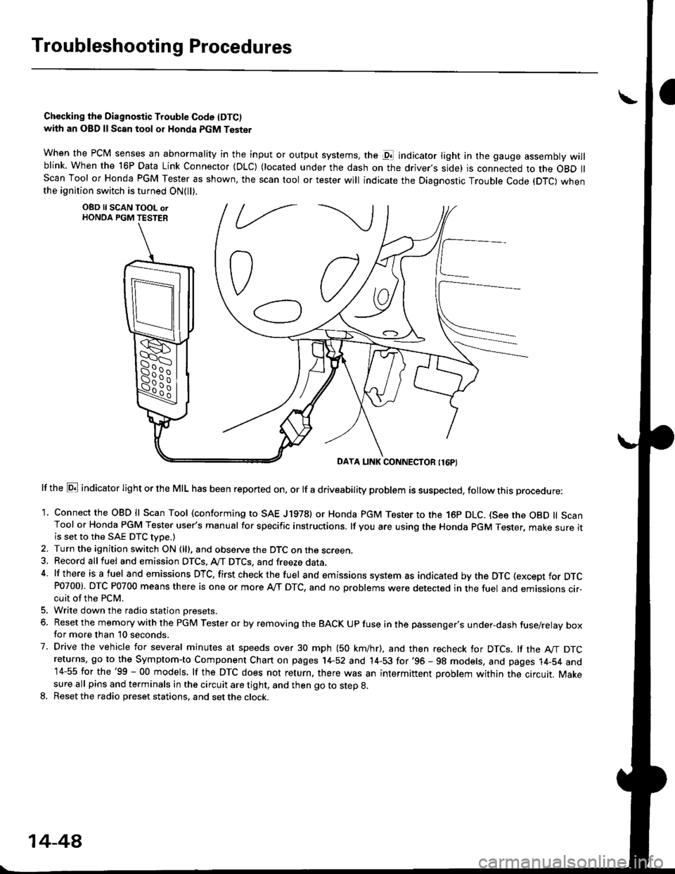
Chccking the Diagnostic Trouble Code IDTC)with an OBD ll Scan tool or Honda PGM Tester
when the PCM senses an abnormality in the input or output systems, the pl indicator light in the gauge assembly willblink. When the 16P Data Link Connector (DLC) (located under the dash on the driver,s side) is connected to the OBD llScan Tool or Honda PGM Tester as shown, the scan tool or tester will indicate the Diagnostic Trouble Code (DTC) whenthe ignition switch is turned ON{ll).
lf the El indicator light or the MIL has been reported on, or lf a driveability problem is suspected, follow this procedure:
1. Connect the OBD ll Scan Tool (conforming to SAE J19781 or Honda PGM Tester to rhe 16p DLC. (See the OBD ll ScanTool or Honda PGM Tester user's manual for specific instructions. lf you are using the Honda PGM Tester, make sure itis set to the SAE DTC type.)
2. Turn the ignition switch ON (lll, and observe the DTC on the screen,3, Record all fuel and emission DTCS, A/T DTCS, and freeze data.4 lf there is a fuel and emissions DTC, first checkthe fuel and emissions system as indicated bythe DTC (except for DTCP0700). DTC P0700 means there is one or more A,/T DTC, and no problems were detected in the fuel and emissions cir-cuit of the PCM.
5. Write down the radio station oresets.
6. Reset the memory with the PGM Tester or by removing the BACK UP fuse in the passenger's under-dash fuse/relay boxfor more than 10 seconds.
7. Drive the vehicle for several minutes at speeds over 30 mph (50 km/hr), and then recheck for DTCS. lf the A"/T DTCreturns, go to the Symptom-to Component Chart on pages 14-52 and 14-53 for'96 - 98 models, and pages 14-54 and14-55 for the'99 - 00 models, lf the DTC does not return, there was an intermittent problem within the circuit. Makesure all pins and terminals in the circuit are tight, and then go to step g.
8. Reset the radio preset stations, and set the clock.
OBD ll SCAN TOOL orHONDA PGM TESTER
DAYA LINK CONNECTOR {16P}
14-44
Page 727 of 2189
Chocking th€ Diagnostic Trouble Code (DTCI
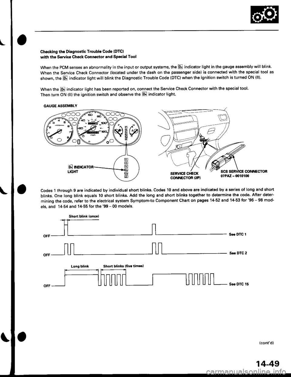
with the Servico Check Conneqtor and Sp€cialTool
When the PCM senses an abnormality in the input or output systems, the @ indicator light in the gauge assembly will blink
When the Service Check Connector (locat€d under the dash on the passengsr side) is connected with the special tool as
shown, the E indicator light will blink the Diagnostic Trouble Code (DTC) when the ignition switch is turned ON (ll).
When the E indicator light has been reported on, connect the Service Check Connector with the special too'.
Then turn ON (ll) the ignition switch and obssrve the E indicator tight.
CONNECTOBSERVICE CHECKCONNECTOR I2PI07PAZ -0010100
Codes 1 through 9 are indicated by individual short blinks, Codes 10 and above are indicat€d by a sories of long and short
blinks. One long blink equals 1O short blinks. Add the long and short blinks together to determine th€ code. After deter-
mining the code, refer to the electrical system Symptom-to Component Chart on pages 1+52 and 1+53 for'96 - 98 mod-
els, and 14-54 and 14-55 for the '99 - 00 models.
S€r DTC 1
s.. DTC 2
Long blinkShort blink lfiYa tim.!,
S€c DTC 15
(cont'd)
GAUGE ASSEMBLY
Short blink loncel
14-49
Page 754 of 2189

Electrical Troubleshooting ('96 - 98 Models)
Troubleshooting Flowchart - E Indicator Light Does Not Gome On
PCM CONNECTOR A I32PI
Wire side of female terminals
Tha E indicator light does nolcome on when the ignition swhchis first turned ON (lll. {lt shouldcome on tol about two s€conds.l
Chock the SeJvico Check Connec-tor:Make sure the special tool (SCS
Seryice Conneclor) is not connect-ed to the service check connector.
ls the special tool (SCS ServiceConnector) connected to the service check connector?
Disconnect the special tool tromthc sarvice check connoctor androcheck.
Check th6 E indicator Light:Shift to lD.l oosition.
Check tor loose PCM connecto6.ll nece3sary, sub.titute a known-good FCM and r.chock.
Check the Ground Circuit:'1. Turn the ignition switch OFF.2. Disconnecr the A {32P}connec-tor lrom the PCM.3. Check for continuity betweenthe A9 terminal and bodyground and the A22 terminaland body ground.
Repair op6n in tho wirgsbetween tho A9 ot M2 tormi-nals and G101.Rcpair poor glound {G101).
To page 14-77
l.
14-76
Page 762 of 2189
Electrical Troubleshooting ('gg - 00 Models)
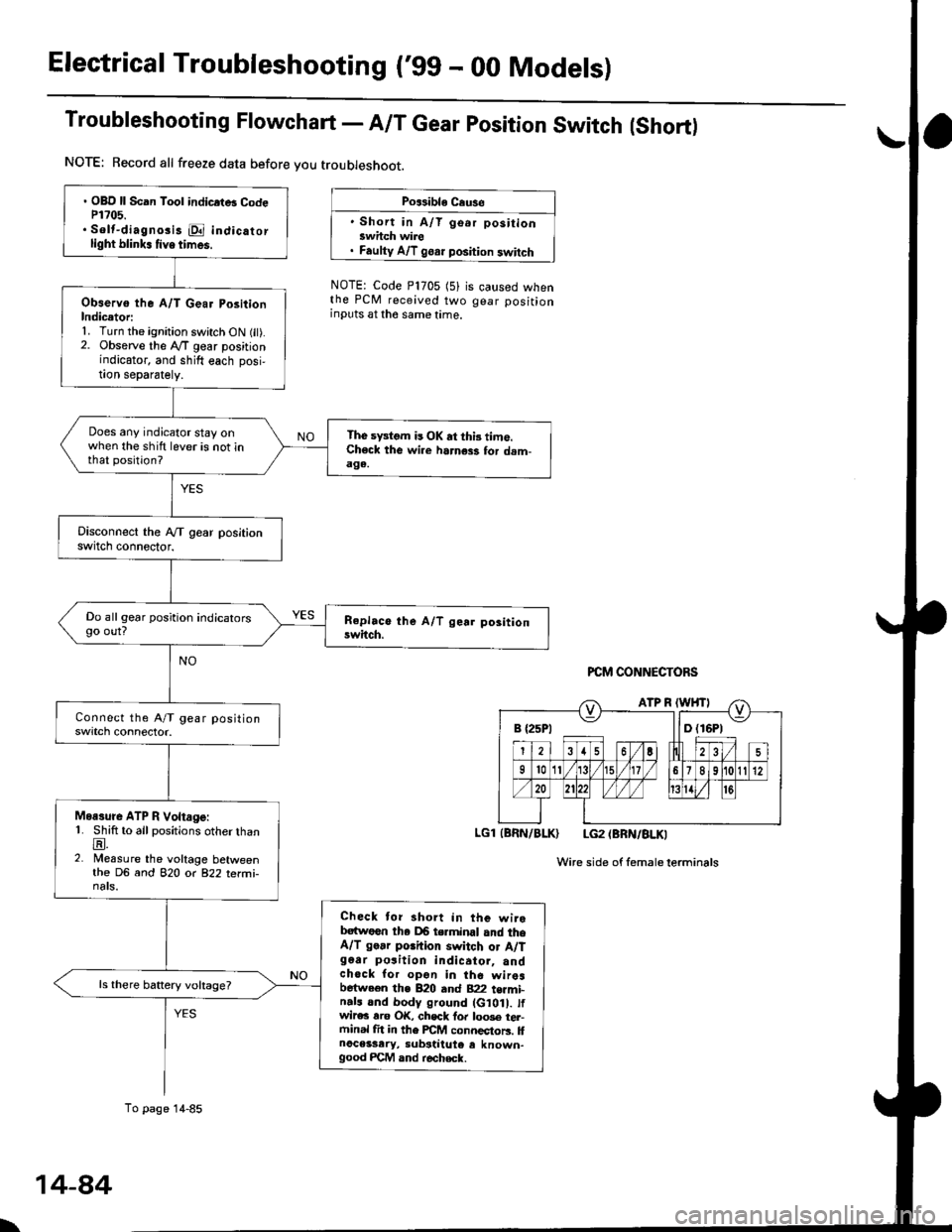
Troubleshooting Flowchart - A/T Gear position Switch (Short)
NOTE: Record all freeze data before you troubleshoot.
Po$ible Cause
' Short in A/T go.r positionswhch wire. Faulty A/T goar position switch
NOTE: Code P1705 (5)the PCM received twoinputs at the same time.
is caused whengear position
PCM CONNECTORS
LGl (BRN/BLK) LG2 (BRN/BLKI
Wire side of femaleterminals
B {25P1 llD (16P1
. OBD ll Scan Tool indicrtB CodeP1?05.. Solt-diagno3i3 E indicatorlight blink. tive times.
Observo the A/T Gear PositionIndicetori1. Turn the ignition switch ON fit).2. Observe the lVT gear positionindicator, and shift each posi,!on separately.
Does any indicator stay onwhen the shift lever is not inthat position?
The sFtom is OK at thi3 time.Check the wi.e harness for dam-aga.
Do all gear position indicatorsgo out?
Moasure ATP R Voltage:1. Shift to all positions otherthanE.2. Measure the voltage betweenthe DG and 82O o( 822 terfii-nats.
Check tor short in the wirebatwoen tha DB terminal and theA/T go.r porhion switch or A/Tg6ar po3ition indicator, andchock for opon in the wiresbetween the B20 and B22 t€rmi-n.ls and body ground (G10 . tfwir€c rro OK, chsck fo. loo3e tel-ftinal fit in the FCM connectors. llnoceisary, substiiute e known-good FCM and r€check.
ls there battery voltage?
To page 14-85
\
14-84
Page 780 of 2189

Electrical Troubleshooting ('99 - 00 Models)
Troubleshooting Flowchart - E Indicator Light Does Not Come On
FCM CONNECTOR B (25P}
LGl {8RN/ALKI{BRN/8LK}
Wire side ol temale terminals
LGl IBNN/BLK} LG2 {BRN/BLK)
i2t5 6q
910t7
LG2
o) (o
The Pll indicator light does notcome on when the ignitionswitch is fi.st turned ON (ll). lltshould come on for about twoseconda.l
Check the Service Check Con-nector:Make sure the special tool (SCS
Service Connector) is not connect-ed to the service check connector?
ls the specialtool {SCS ServiceConnector) is not connected tothe seNice check connector.
Disconnect the special tool fromthe service check connector andr6check.
Check the Dll lndicator LightiShift to d position.
Check for loose terminal fit in thePCM connecto13. It necessary.sub3titute a known-good PCMand recheck.
Does the @ indicator lightcome on?
Check the Ground Circuit:1. Turn the ignition switch OFF.2. Disconnect the B (25P) con-nector from the PCM.3. Check for continuity betweenthe 820 terminal and bodyground, and between the 822terminal and body ground.
Repair open in the wiresbetween the B20 rnd 822 termi-nals and ground (G101), andrep.ir poor ground (G1011.
Measure Power Supply CircuitVoltage:1. Turn the ignition switch ON {ll}.2. Measure the voltage betweenterminals B1 and 822 andbetween terminals Bg and820.
Repair open or short in the wi.obetween th6 81 and/or 89 termi-nals and the PGM-FI main relav,and between th€ PGM-FI mainr€ley rnd the under-hood tus€/relay box.
To page 14''103
14-102
Page 783 of 2189
Lock-up Gontrol Solenoid Valve A/B Assembly
Test
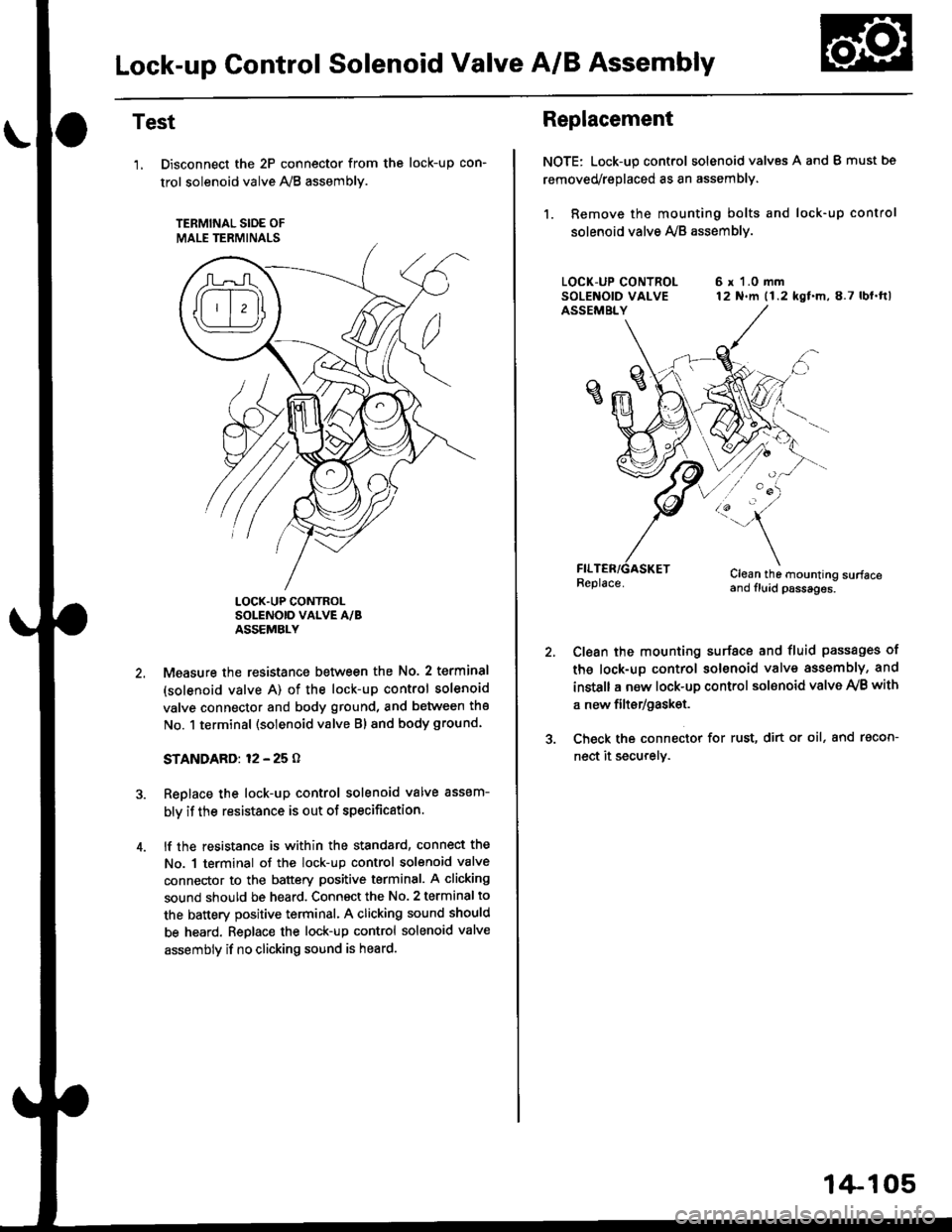
'1, Disconnect the 2P connector from the
trol solenoid valve 1y'8 assembly.
TERMINAL SIOE OF
MALE TERMINALS
tocK-up con-
LOCK.UP CONTROLSOLENOID VALVE A/BASSEMBLY
Measure the resistance between the No. 2 terminal
(solenoid valve A) of the lock-up control solenoid
valve connector and body ground, and between the
No. 1 terminal (solenoid valve Bl and body ground.
STANDARD: 12 - 25 O
Replace the lock-up control solenoid valve assem-
bly if the resistance is out of specification.
lf the resistance is within the standard, connect the
No. 1 terminal of the lock-up control solenoid valve
connector to the battery positive terminal. A clicking
sound should be heard. Connsct the No. 2 terminal to
the battery positive terminal. A clicking sound should
be heard. Replace the lock-up control solenoid valve
assembly if no clicking sound is heard.
Replacement
NOTE: Lock-up control solenoid valves A and I must bs
removed/replaced as an assembly.
1. Remove the mounting bolts and lock-up control
solenoid valve Ay'B assemblv.
6 r 1.0 mm12 N.m (1.2 kgf.m,8.7 lbl.ftl
/:'-
Clean the mounting surfaceand fluid psssages.
Clean the mounting surface and fluid passages of
th6 lock-up control solenoid valve assembly, and
instsll a new lock-up control sol€noid valve Ay'B with
a new filtsr/gask€t.
Check the connector for rust, dirt or oil, and racon-
nect it securely.
1+105
Page 784 of 2189
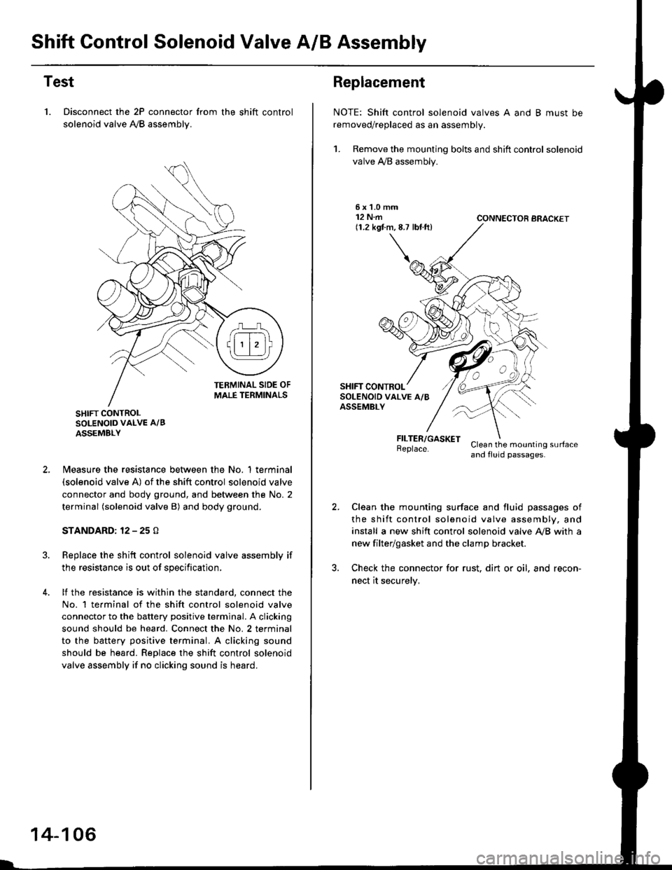
Shift Control Solenoid Valve A/B Assembly
Test
1. Disconnect the 2P connector from the shift control
solenoid valve A,/B assemblv.
SHIFT CONTROLSOLENOID VALVE A/B
ASSEMBLY
N4easure the resistance between the No. 1 terminal(solenoid valve A) of the shift control solenoid valve
connector and body ground, and between the No. 2
terminal (solenoid valve B) and body ground.
STANDARD: 12 - 25 O
Replace the shift control solenoid valve assembly if
the resistance is out of specification,
lf the resistance is within the standard, connect the
No. 1 te.minal of the shift control solenoid valve
connector to the battery positive terminal. A clicking
sound should be heard. Connect the No. 2 terminal
to the battery positive terminal. A clicking sound
should be heard. Replace the shift control solenoid
valve assembly if no clicking sound is heard.
14-106
Replacement
NOTE: Shift control solenoid valves A and B must be
removed/replaced as an assembly.
1. Remove the mounting bolts and shift control solenoid
valve A,/B assembly.
5xL0mm12 N.m(1.2 kgf.m,8.7 lbf.ft)CONNECTOR BRACKET
FILTER/GASKETBeplace.Clean the mounting surfaceand fluid passages.
Clean the mounting surface and fluid passages of
the shift control solenoid valve assembly, and
install a new shift control solenoid valve Ay'B with a
new filter/gasket and the clamp bracket.
Check the connector for rust. dirt or oil. and recon-
nect it securelv,