Page 632 of 2189

Transmission Assembly
lnstallation
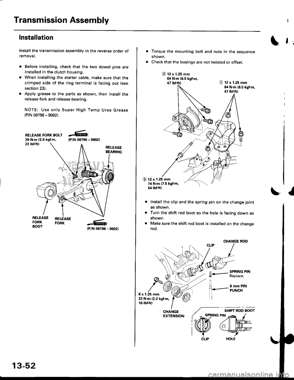
Install the transmission assembly in the reverse order of
removal.
. Before installing, check that the two dowel pins are
installed in the clutch housing.
. When installing the starter cable. make sure that the
crimped side of the ring terminal is facing out (see
section 23).
. Apply grease to the parts as shown, then install the
release fork and release bearing.
NOTE; Use only Super High Temp Urea Grease(P/N 08798 -9002).
RELEASE FORK BOLT29 N.m 13.0 kgf.m,22 tbllrl
(P/N 08798 - 9rD2l
-R1
tP/N 08798 -
13-52
CLIP
L f ;
Torque the mounting bolt and nuts in the sequence
shown.
Check that the busings are not twisted or offset.
@ t2 x 1.25 mm6,t N.m 16.5 kgtm,47 lbf.ft)O t2 x 1.25 mm6,r N.m (6.s kg{.m,17 tbf.ft)
O 12 x 1.25 mm7ilNm17.5kgf.m,5it lbt ft)
I
Install the alip and the spring pin on the change joint
as snown.
Turn the shift rod boot so the hole is facing down as
snown.
Make sure the shift rod boot is installed on the changerod.
CHANGE ROO
FL.- SPRING PINll heptace,
8 mm PINPUNCH
/ "*,*
lo,iD(
CHANGE ./EXTENSfoN ( ^ st
l?rffi
l\K
Page 651 of 2189
Disassembly
1. Remove the ball bearing using a bearing puller as
shown.
BEABING PULLER
BALL BEARING
CAUTION: Remove the synchro hubs using a ptess
and the sts€l blocks as shown. Use of a i8w'type
puller can cause damage to th€ gear teeth.
Support sth gear on steel blocks, and press the
mainshaft out of the sth synchro hub, as shown.
3. Support 3rd gear on steel blocks, and press the
mainshaft out of the 3rd/4th svnchro hub, as shown.
13-71
Page 652 of 2189
Mainshaft Assembly
Inspection
1. Inspect the gear surfaces and the bearing surfaces
for wear and damage. then measure the mainshaft
at points A, B, and C. lf any parts of the mainshaft
are less than the service limit, reDlace mainshaft
with a new one.
Standard:
A: 27.987 - 28.000 mm {1.1018 - 1.1024 in}
B: 37.98i1 - 38.fi)0 mm (1.,|!t5,0 - 1.4960 inl
Ci27.977 - 27.990 mm 11.1015 - 1.1020 inl
Service Limit:
A; 27.940 mm {1.1000 in}
B: 37.930 mm (1./{133 in)
C:27.930 mm (1.0996 inl
(
2. Inspect for runout. lf the runout is more than the
service limit, replace the mainshaft with a new one,
Standard: 0.02 mm 10.0008 inl max.
Ssrvice Limit: 0.05 mm 10.002 inl
NOTE: Suooort the mainshaft at both ends as
shown.
t
Inspect for wearano oamage.
Inspect oil passages tor clogging.
13-72
Page 653 of 2189

Reassembly
CAUTION:
. Press the 3rd/4th and the 5th synchro hubs on the
mainshaft without lubrication.
o When installing the 3rd/,lth and the sth synchro
hubs, support the mainshaft on steel blocks, and
installthe synchro hubs using a prsss.
. Install the 3rd/4th and the sth synchro hubs with a
maximum plessur€ of 19.6 kN (2,000 kg, 14,466 lbl.
NOTE: Refer to page 13-67 for reassembly sequence.
1, Support 2nd gear on steel blocks, then install the
3rd/4th synchro hub using the special tools and a
press, as snown.
NOTE:
. After installing. check the operation of the
3rd/4th synchro sleeve and hub.
. Assemble the 3rd/4th synchro hub and sleeve
together betore installing them on the mainshaft.
Closed end
3RD/4THSYNCHRO HU3DBIVER, 10 mm l.O.07746 - 00301U)
/ lrrlcHlileNr. ss .- t.o.07746 - 0030,100
l.
3RD/{THSYNCHROSLEEVE
2ND GEAR
2. Install the sth synchro hub using the special tools
and a press as snown.
DRIVER, {0 mm l.O.07746 - 0030100
ATTACHMENT,35 mm LD.
sTH SYNCHRO HUB
07716 - 0030,100
3. Install the angular ball bearing using the special
tools and a press as shown.
PRESS
+
DRIVER, 40 mm LD.0?7a6 - It030100
Page 656 of 2189
Gountershaft Assembly
Disassembly
1. Securely clamp the countershaft assemblv in a
bench vise with wood blocks.
2. Raise the locknut tab from the groove in the coun-
tershaft, then remove the locknut and the spring
washer.
Remove the ball bearing using a bearing pulle. asshown.
BEARING PULLER
BALL BEARING
13-76
4, Remove the bearing outer race, then remove theneedle bearing using a bearing puller as shown.
BEARING PULLEF
BEARING
CAUTION: Romove the gears using a pr63 and the
stesl blocks as shown, Use of a ,aw-typo puller can
cause damage lo lhe gear tooth.
Support 4th gear on steel blocks, and press thecountershaft out of sth and 4th gears, as shown.
sTH GEAF
{TH GEAR
.(
a
ItI
Page 657 of 2189
t
Inspection
1. Inspect the gear surfaces and the bearing surfaces
for wear and damage, then measure the counter-
shaft at points A, B, and C. lf any parts of the coun-
tershaft are less than the service limit. reDlace coun-
torshaft with a new one.
Standard:
A: 2/t.980 - 2{.993 mm (0.9835 - 0.9&O in}
B: 35.984 - 37.000 mm {1.4561 - 1.4567 in)
G: 33.fiD - 33.015 mm {1.2992 - 1.2998 in)
Sorvicc Limit:
Ar 2/t.9't0 mm 10.9819 inl
B: 36.930 mm {1.'l5qt in}
C: 32.950 mm {1.2972 in}
Insp€ct for wear
Inspect oil passage for clogging.
13-77
2. Insoect for runout. lf the runout is more than the
service limit, reolace the countershaft with a new
one.
Strndard: 0.02 mm {0.(x)08 in) max.
Servic. Limit 0.05 mm (0.002 in)
NOTE: SuoDort th€ countershaft at both ends as
shown.
Rotate lwo complelerevotutons.
Page 658 of 2189

Gountershaft Assembly
Reassembly
CAUTION:
. Pross 4th and sth gears on the countershaft without
lubrication.
. When installing ilth and sth geafs, support the shaft
on steel blocks, and install the gears using a press.
. Install ilth and sth gear with a maximum pressure of
25.5 kN (2,600 ksf, 18,806lbf).
NOTE; Refer to page 13-74 for reassembly sequence.
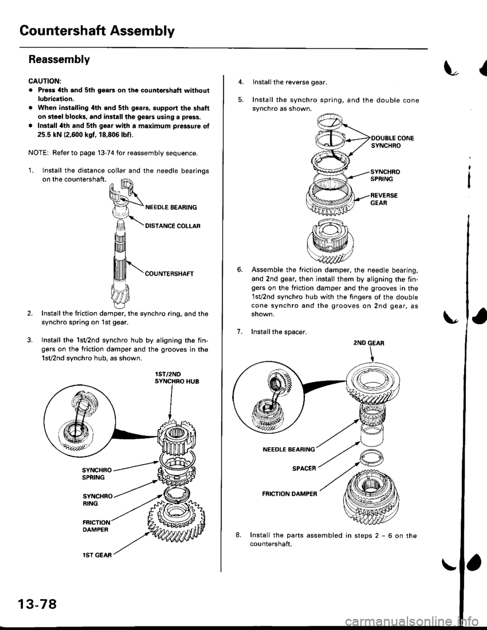
'1. Install the distance collar and the needle bearinos
on the countershaft.
COUNTERSHAFT
Install the friction damper, the synchro ring, and the
synchro spring on 1st gear.
Install the 1sv2nd synchro hub by aligning the fin-
gers on the friction damper and the grooves in the
1sv2nd synchro hub, as shown.
lST/2NO
13-78
lSI GEAR
insteps2-6onthe
{
4.lnstall the reverse gear.
Install the synchro spring. and the double cone
synchro as shown.
Assemble the friction damper, the needle bearing,
and 2nd gear, then install them by aligning the fin-gers on the friction damper and the grooves in the
1sv2nd synchro hub with the fingers of the double
cone synchro and the grooves on 2nd gear, as
snown.
Installthe spacer.
FRICTION DAMPER
Install the parts assembled
countershaft.
;
2ND GEAR
Page 661 of 2189

Synchro Ring, Gear
Inspection
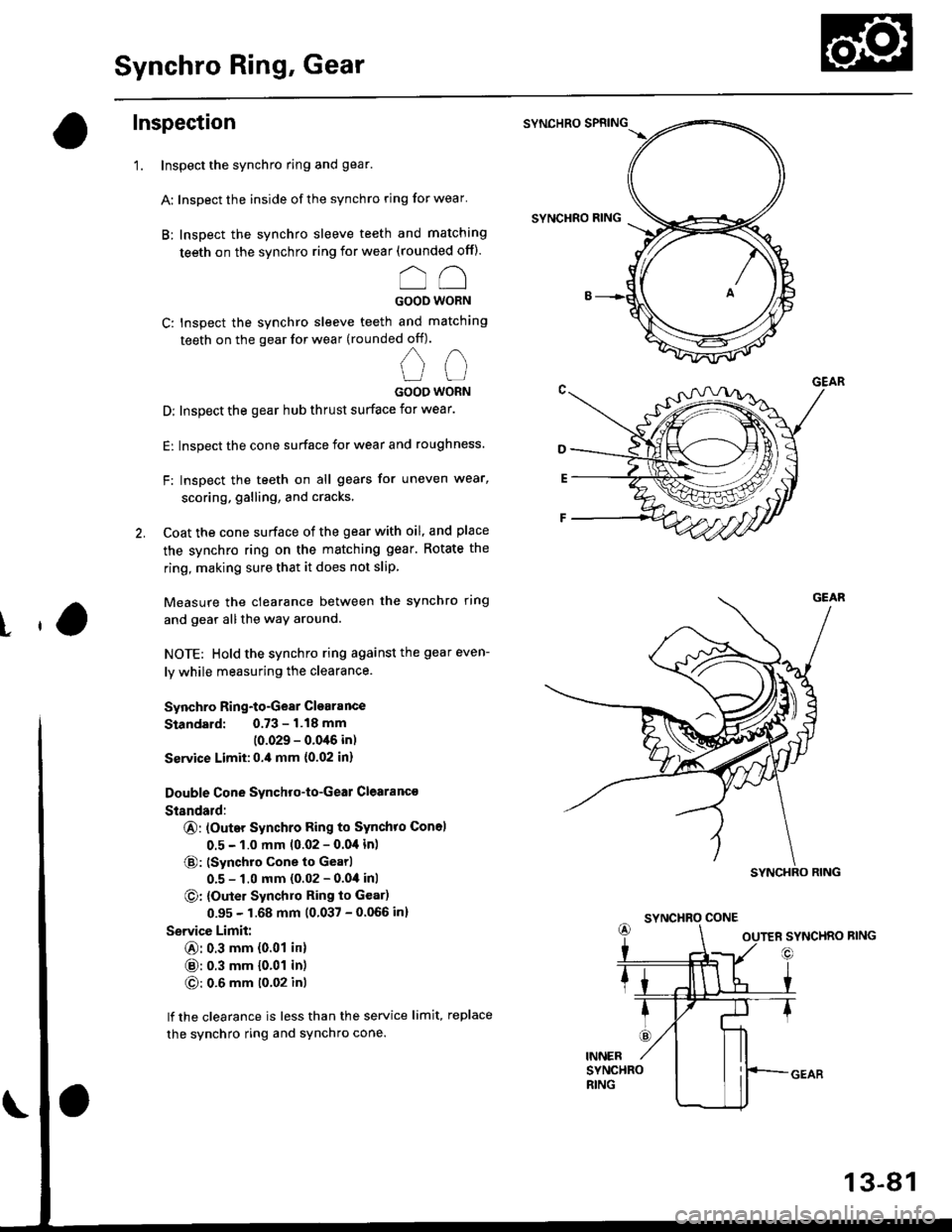
'1. Inspect the synchro ring and gear.
A: Inspect the inside of the synchro ring for wear'
B: Inspect the synchro sleeve teeth and matching
teeth on the synchro ring for wear (rounded off).
oo
GOOD WORN
C: Inspect the synchro sleeve teeth and matching
teeth on the gear for wear (rounded off).
nn
UUGOOO WORN
D: Inspect the gear hub thrust surface for wear.
E: Inspect the cone surface for wear and roughness.
F: Inspect the teeth on all gears for uneven wear,
scoring, galling, and cracks'
2. Coat the cone surface of the gear with oil, and place
the synchro ring on the matching gear. Rotate the
ring, making sure that it does not slip
Measure the clearance between the synchro ring
and gear allthe way around.
NOTE: Hold the synchro ring against the gear even-
ly while measuring the clearance.
Synchro Ring-to-Gear Clearance
Standard: 0.73 - 1.18 mm
(0.029 - 0.0'16 in)
Ssrvice Limit:0.,0 mm {0.02 in}
Double Cone Synchro-to-Geal Clearanc€
Standald:
@: (Outer Synchro Ring to Synchro Con6l
0.5 - 1.0 mm 10.02 - 0.04 in)
@: (Synchro cone to Gearl
0.5 - 1.0 mm (0.02 - 0.04 inl
O: {Outer Synchlo Ring to Gear)
0.95 - 1.68 mm (0.037 - 0.066 in)
Service Limit:
@: 0.3 mm {0.01 in}
@: 0.3 mm {0.01 in)
O: 0.6 mm t0'02 inl
lf the clearance is less than the service limit, replace
the synchro ring and sYnchro cone.
SYNCHRO SPRING
SYNCHRO RING
t
SYNCHRO CONE
13-81