Page 559 of 2189

Emission Control System
Ch€ck the EVAP purge controlsolenoid valv6:1. Disconnect the 2P connectorfrom the EVAP purge controlsolenoid valve.2. Ouickly raise the engine speedto 3,000 rpm.
Insped vacuum hose routing.lf OK. roplace the EVAP purge
control solonoid valve.
Chock tor r short in the wir€
{PCS line):1. Turn the ignition switch OFF.2. Disconnect ECM/PCM connec-tor A (32P).
3- Check tor continuity betweenthe EVAP purge control sole-noid valve 2P connector termi-nal No. 2 and body ground.
Check the vacuum when hot:1. Turn the ignition switch OFF.2. Block the rear wheels and setthe parking brake.3. Jack up the lront of the vehi-cle and support it with safetystands.4. Start the engine. Hold theengine at 3,000 rpm with noload (in Park or neutrali until
the radiator fan comes on, thenlet it idle.5. Check for vacuum at the vac-uum hose with transmissionin gear (A/T in E position,
lvl/T in 1st gear) after startingthe engine.6. Ouickly raise the engine speedto 3,000 rpm.
Rooair shoft in the wire belwegnthe EVAP pulg6 control solenoidvalvs and tho ECM/PCM {A61.ls there continuity?
Substitute a known-good ECM/PCM and rech6ck. lt 3ymptom/indicrtion 90e3 rway, r6plac6 th€o.iginal ECM/FCM.
Check th€ EVAP purge controlsolenoid valve:1. Turn the;gnition switch OFF.2. Disconnect the 2P connectorfrom the EVAP purge controlsolenoid valve and warm itup to normal operating tem-perature again if necessary.3. Start the engine.4- At the harness side, measurevoltage between the EVAPpurge control solenoid valve2P connector terminal No. 1and No.2 with the transmis-sion in gear {A/T in E posi-tion, M/T in lst geari.
In3pect vacuum hoae routing.lf OK, repl.ce EVAP purge con-trol solonoid valve.ls there battery voltage?
Chock for an open in the wire(lG1 lina):At the harnoss side, measure volt-age beNveen the EVAP purge con-trol solenoid valve 2P connectorterminal No. 1 and body ground.
Repair open in the wire b€lwe€nEVAP purge contrl 3olenoid valv6and lhe No. 15 ALTERNATOR SPSENSOR 17.5 A, fu3e.
ls there battery voltage?
Evaporative Emission (EVAPI Controls (cont'dl
(From page 11-289)
(To page 11-291)
11-290
IJ
EVAP PURGE CONTROL SOLENOIDVALVE 2P CONNECTOR IC114I
PCS
IRED/YEL)
temaletermrnars
of
PCS(RED/YEL)
tGlIBLK/YEL)
{To page 11 291)
Page 571 of 2189

Glutch Pedal
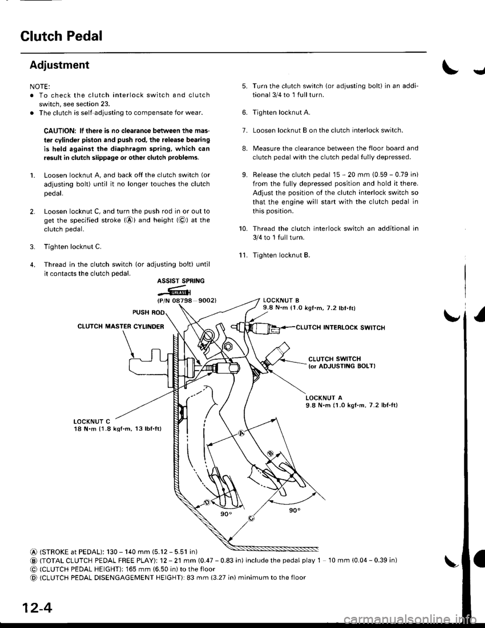
Adjustment
NOTE:
. To check the clutch interlock switch and clutch
switch, see section 23.
. The clutch is self-adjusting to compensate for wear.
CAUTION: lf there is no clearance between the mas-
ter cylinder pislon and push rod, the release bearing
is held against the diaphragm spring, which can
result in clutch slippage 01 other clutch problems.
1. Loosen locknut A, and back off the clutch switch (or
adjusting bolt) until it no longer touches the clutch
peoar.
2. Loosen locknut C, and turn the push rod in or out to
get the specified stroke {@} and height (@) at tne
clutch pedal.
3. Tighten locknut C.
4. Thread in the clutch switch {or adiusting bolt) until
it contacts the clutch pedal.
9002)
Turn the clutch switch (or adjusting bolt) in an addi-
tional 3/4 to 1 full turn.
Tighten locknut A.
Loosen locknut B on the clutch interlock switch.
Measure the clearance between the floor board and
clutch pedal with the clutch pedal fully depressed.
Release the clutch pedal 15 - 20 mm {0.59 - 0.79 in)
from the fully depressed position and hold it there.
Adjust the position of the clutch interlock switch so
that the engine will start with the clutch pedal in
this position.
Thread the clutch interlock switch an additional in
3/4 to 1 full turn.
Tighten locknut B.
LOCKNUT B9.8 N.m (1.0 k91.m,7.2 lbt.tt)
INTERLOCK SWITCI{
J
'lL
5.
7.
8.
9.
10.
ASSIST SPRING
-Atl
CLUTCH SWITCH
lo. ADJUSTING BOLTI
LOCKNUT A9.8 N'm (1.0 kgI.m, 7.2 lbf,ft)
LOCKNUT C18 N.m {1.8 kql.m, 13lbf.ft}
@ (STROKE at PEDAL): 130 - 140 mm (5.12 - 5.51 in)
@ (TOTAL CLUTCH PEDAL FREE PTAYI: 12 - 21 mm (0.47 - 0.83 in) includethepedal play 1 10 mm (0.04 - 0.39 in)
@ (CLUTCH PEDAL HEIGHT): '�]65 mm {6.50 in) to the floor
@ (CLUTCH PEDAL DISENGAGEMENT HEIGHT): 83 mm (3.27 in) minimum to the floor
12-4
Page 572 of 2189
Glutch Master Gylinder
IRemovaUlnstallation
CAU'NON:
. Do not sDill brake lluid onthevehicle;it may damage
the paint; if brake fluid does contact the paint, wash
it off immediatelY with water.
. Plug the end ofthe clutch line and reservoir hos€ with
a shop towelto prevent brake tluid from coming out
1. The brake tluid can be removed from the clutch
master cylinder reservoir with a syringe
2. Disconnect the clutch line and reservoir hose from
the clutch master cylinder.
19N.m 11.9 kgf.m,14 tbf.ttl
[.
3. Pry out the lock pin, and pull the pedal pin out
the yoke. Remove the nuts
NUTS8 x 1 .25 mm13 N.m {'1.3 kgt.m,9.4lbf ft)
)
of
CLUTCH LINE
iffi,
4. Remove the clutch master cylinder.
CLUTCH MASTER CYLINDER
lnstall the clutch master cylinder in the reverse
order of removal.
NOTE: Bleed the clutch hydraulic system {see page
12-61,
12-5
Page 576 of 2189

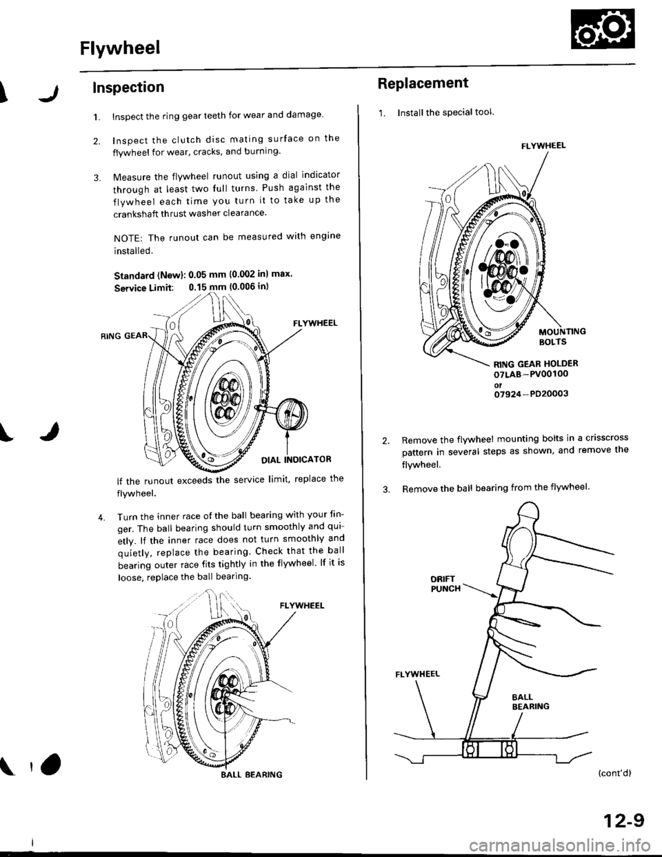
Flywheel
\Inspection
1.
2.
3.
Inspect the ring gear teeth for wear and damage
Inspect the clutch disc mating surface on the
flywheel for wear, cracks, and burning.
Measure the flywheel runout using a dial indicator
through at least two full turns Push against the
flywheel each time you turn it to take up the
crankshaft thrust washer clearance.
NOTE: The runout can be measured with engine
installed.
Standard (New): 0.05 mm (0.002 inl max.
Service Limit: 0.15 mm {0.006 in)
FLYWHEEL
OIAL INOICATOR
FLYWHEEL
lf the runout exceeds the service limit. replace the
flywheel.
Turn the inner race o{ the ball bearing with your tin-
ger. The ball bearing should turn smoothly and qui
etly. lf the inner race does not turn smoothly and
quietly, replace the bearing. Check that the ball
bearing outer race fits tightly in the flywheel. lf it is
loose. replace the ball bearing
IJ
4.
BALL BEARING tO
Replacement
1. Installthe special tool.
MOUNTINGBOLTS
RITIG GEAR HOLDER
oTLAB-PV00100oto7924-PD20003
2.Remove the flywheel mounting bolts in a crisscross
pattern in several steps as shown, and remove the
flywheel,
Remove the ball bearing from the flywheel
(cont'dl
12-9
FLYWHEEL
t\
m\J
Page 583 of 2189

MaintenanceBack-up Light Switch
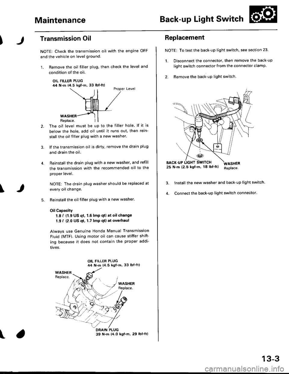
Transmission Oil
NOTE: Check the transmission oil with the engine OFF
and the vehicle on level ground.
1. Remove the oil filler plug, then check the level and
condition of the oil.
OIL FILLER PLUG/14 N.m (4.5 kgl.m,33 lbl.ft)Proper Level
4.
WASHERReplace.
The oil level must be up to the filler hole. lf it is
below the hole, add oil until it runs out. then rein-
stall the oil filler plug with a new washer.
lf the transmission oil is dirty, remove the drain plug
and drain the oil.
Reinstall the drain plug with a new washer, and refill
the transmission with the recommended oil to the
proper lever.
NOTE: The drain plug washer should be replaced at
every oil change.
Reinstall the oil filler plug with a new washer.
OilCapacity
1.8 f (1.9 US qt. 1.6 lmp qtl at oil change
1.9 { (2.0 US $, 1.7 lmp qt) at overhaul
Always use Genuine Honda Manual Transmission
Fluid {MTF). Using motor oil can cause stiffer shift-
ing because it does not contain the proper addi-
t|ves.
\
\
Replacement
NOTE: To test the back-up light switch, see section 23
1. Disconnect the connector, then remove the back-up
light swirch connector from the connector clamp.
2. Remove the back-up light switch.
25 N.m (2.5 kgf'm, 18lbf'ltl
Install the new washer and back-up light switch
Connect the back-up light switch connector.
ASHER
13-3
Page 588 of 2189

Transmission Assembly
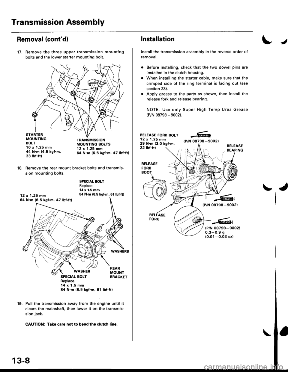
Removal(cont'd)
17. Remove the three upper transmission mounting
bolts and the lower starter mounting bolt,
STARTERMOUNTINGBOLT10 x 1.25 mm44 N.m (4.5 kgf.m,33 rbnftl
TRANSMISSIONMOUI{TING EOLTS12 x 1.25 mm& N.m (6.5 kgt'm,47 lbl.ftl
18. Remove the rear mount bracket bolts and transmis-
sion mounting bolts.
12 x 1.25 mm64 N.ft 16.5 kgl.m,47 lbl.ftl
SPECIAL BOLTReplace.'ll x 1.5 mm84 N.m (8.5 kgf.m, 61 lbf.ftl
SPECIAL BOLTReplace.14 x 1,5 mln84 N.m (8.5 kgl.m, 61
WASI{ERREARMOUNTBRACKET
rbl.ftt
Pull the transmission away from the engine until it
clears the mainshaft. then lower it on the transmis-
sion jack.
CAUTION: Take caro not to b6nd tho clutch lin€.
1(|
Installation
Install the transmission assembly in the reverse order of
removal.
Before installing, check that the two dowel pins are
installed in the clutch housing.
When installing the starter cable, make sure that the
crimped side of the ring terminal is facing out (see
section 23).
Apply grease to the parts as shown, then install the
release fork and release bearing,
NOTE: Use only Super High Temp Urea Grease
(P/N 08798 - 9002).
RELEASE FORK BOLT12 x 1.25 mm29 N'm 13.0 kgt,m,(P/N 08798-90021
22 tbl.ttlR€LEASEBEARING
J
RELEASEFORK8()07
ra
{PiN 08798-9002)
tP/N 08798-900210.3-0.9 g
10.01-0.03 ozl
Page 595 of 2189

Mainshaft Assembly
I
lndex
Note the following during reassembly:
. The 3rd/4th and sth svnchro hubs are installed with a press
. Install the angular ball bearing with the thin-edge outer race facing the sth synchro hub
. Install the ball bearing with the ball cage facing up
prior to reassembling, clean all the parts in solvent, dry them and apply lubricant to all contact surfaces the 3rd/4th
and sth svnchro hubs.
Ballcage faces uP.
Thin edge of outerrace laces down.
3RD/4TH SYNCHRO SLEEVE
page 13'27
SYNCHRO SPRINGSYNCHRO RINGInspection,page 13-28
BALL BEARING {*1)ANGULAR BALL BEARING ('2)
Check for wear and operataon.Note the direction ot installation
5TH SYNCHROSLEEVElnspection, page 13-27
SYNCHRO HUB
SYNCHRO RINGInspection, pase 13 28
sTH GEARInspection, page 13-17
3RD GEARlnspection, page 1 3-1 6
34 x 39 x 27.5 mmNEEDLE BEARINGCheck for wearano opetaflon,
MAINSHAFTInspection, page 13-18
CHAMFEB
32 x 37 x 23.5 mmNEEDLE BEARINGCheck for wear andoperation.SPACER COLLABInspection, page 1316
34x39x23mmNEEDLE EEARINGCheck for wearand operation,
4TH GEARrnspeclron,
*1: D16Y7 engine*2: D16Y5, D16Y8 engines
page 13'16RINGInspectaon, page 13 28
SPRING
13-15
Page 597 of 2189

T
6. Measure the clearance between the spacer collar
and sth gear.
Standard: 0.06 - 0.19 mm 10.002 - 0.007 inl
Service Limit: 0.31 mm (0.012 inl
4TH GEAR
DIALINDICATOR
I
-<=q,
7.
5TH GEAR
lf the clearance is more than the service limit, mea-
sure distance @ on the spacer coilar
Standard: 23.53 - 23.56 mm
10.926 - 0.928 in)
Sowice Limit 23.51 mm {0.926 in}
SPACERCOLLAR
sTH GEARSIDE
lf distance @ is less than the service limit, replace
the spacer collar with a new one,
lf distance @ is within the service limit, measure
thickness of 5th gear.
Siandatd:28.1:2 - 28.17 mm
11.119 - 1.121 in)
Servica Limit: 28.35 mm (1.116 inl
sTH GEAR
lf the thickness of 5th gear is less than the ser-
vice limit, replace sth Oear with a new one.
lf the thickness of sth gear is within the service
limit, replace the 5th synchro hub with a new
one.
Disassembly
1. Remove the ball bearing using a bearing puller as
shown.
BEARING PULLER(Commercially
availablel
CAUTION: Remov€ ths synchro hubs using a press
and steel blocks as shown. Us€ of a iaw-type pullel
can caus€ damage lo the gear teeih.
Support 4th gear on steel blocks. and press the
mainshaft out of the sth svnchro hub as shown.
{cont'd)
13-17