1996 HONDA CIVIC out
[x] Cancel search: outPage 848 of 2189

Differential
Oil Seal Installation/Side Clearance (cont'd)
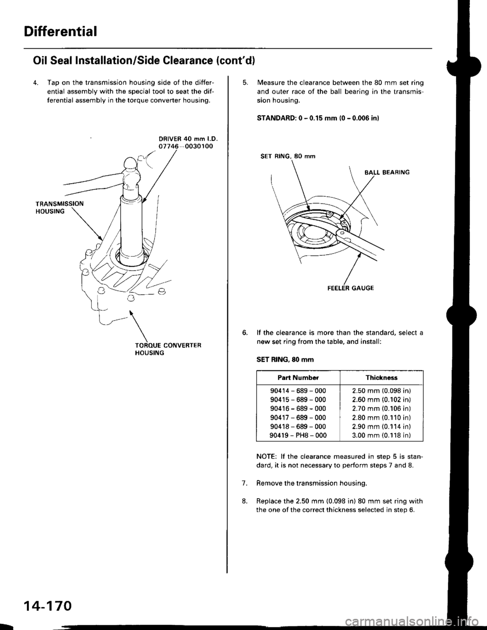
4. Tap on the transmission housing side of the differ-
ential assembly with the special tool to seat the dif-
ferential assembly in the torque converter housing.
DRIVER 40 mm l.D.
L
14-170
5. N4easure the clearance between the 80 mm set ring
and outer race of the ball bearino in the transmis-
sion housing.
STANDARD: 0 - 0.15 mm (0 - 0.006 inl
SET RING, 80 mm
BALL BEARING
lf the clearance is more than the standard, select a
new set ring from the table, and install:
SET RING, 80 mm
NOTE: lf the clearance measured in step 5 is stan-
dard, it is not necessary to perform steps 7 and 8.
Remove the transmission housing.
Replace the 2.50 mm (0.098 in) 80 mm set ring with
the one of the correct thickness selected in step 6.
7.
Part NumberThickness
90414-689-000
904r5-689-000
90416-689-000
90417-689-000
90418-689-000
904r9-PH8-000
2.50 mm (0.098 in)
2.60 mm {0.102 in)
2.70 mm {0.106 in)
2.80 mm (0.110 in)
2.90 mm (0.114 in)
3.00 mm (0.118 in)
Page 852 of 2189

Transmission Housing Bearings
L
Mainshaft/Countershaft Bearings Replacement
To remove the mainshaft and countershaft bearings
from the transmission housing, expand each snap
ring with snap ring pliers, then push the bearing out
using the special tools and a press as shown.
NOTE: Do not remove the snap rings unless it's
necessary to clean the grooves in the housing.
DRIVER07749 - 0010000
ATTACHMENT,62x68mm
PRESS
\
07746 -
DFIVEB07749 - 0010000
TTACHMENT
ATTACHMENT
. Mainshaft Bearing Installation us€:
ATTACHMENT. 72 x 75 mm
07746 - 0010600. Countershaft Bearing Installation use:
ATTACHMENT, 62 x 68 mm
077/16 - 0010500
IRN{L{r.)n
\bZ
MAINSHAFT BEARING
L
14-174
SNAP RING
Expand each snap ring with snap ring pliers, insert
the new bearing part-way into the housing using
the special tools and a press as shown, Install thebearing with the groove facing outside the housing.
NOTE: Coat all parts with ATF.
Release the pliers, then push the bearing down intothe housing until the ring snaps in place around it.
07749 - 0010000
ATTACHMENT
. Mainshaft Bearing Removal use:
ATTACHMENT, 72 x 75 mm
077/16 - 0010600. Counte6haft Bsaring Removal use:
ATTACHMENT, 62 x 68 mm
07746 - 0010500
After installing the bearing verify the following:
. The snap ring is seated in the bearing and hous-
ing grooves.
. The ring end gap is correct.
(0 - 0.28 in)ENDGAP:0-7mm
Page 853 of 2189

Reverse ldler GearPark Stop
lnstallation
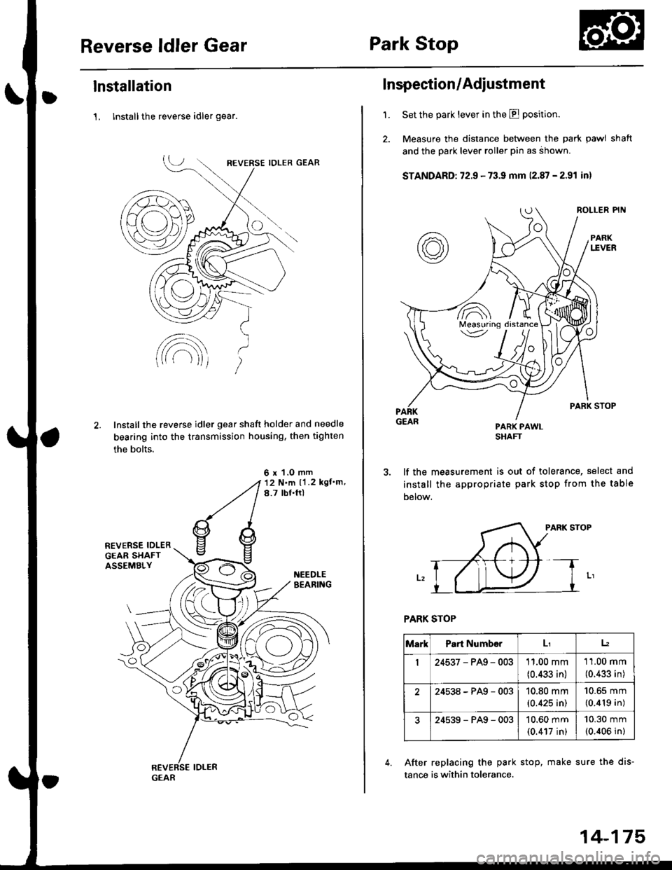
1, lnstall the reverse idler gear.
Install the reverse idler gear shaft holder and needle
bearing into the transmission housing, then tighten
the bolts.
6 x 1.0 mm12 N.m ll .2 kgf'm,
8.7 tbf.ftl
GEAR
'1.
Inspection/Adiustment
Set the park lever in the E position.
Measure the distance between the park pawl shaft
and the park lever roller pin as ahown.
STANDARD: 72.9 - 73.9 mm 12.87 - 2.91 inl
PARK PAWLSHAFT
lf the measurement is out of tolerance, select and
install the appropriate park stop from the table
Delow.
PARK STOP
PARK STOP
After replacing the park stop, make sure the dis-
tance is within tolerance.
/A\Measuring\v
MarkPart Numb€rLr12
I24537-PAg-00311.00 mm
(0.433 in)
11.00 mm
(0.433 in)
24538-PAg-00310.80 mm(0.425 in)
10.65 mm
(0.419 in)
24539-PAg-00310.60 mm(0.417 in)
10.30 mm(0.406 in)
14-175
Page 863 of 2189

16. Install a new set ring on the end of each driveshaft'
17. Installthe right and left driveshafts (see ssction 16)
CAUTION: Whil6 installing the driveshafE in the
diffarential, be surs not lo allow du3t and othor for-
eign particl€s to enler into the transmission.
NOTE:
. Clean the areas where the driveshafts contact the
transmission (differential) thoroughly with sol-
vent or carburetor cleaner, and dry with com-
pressed air.
. Turn the right and left steering knuckle fully out-
ward, and slide each driveshaft into the differen-
tial until you feel its set ring clip engage the side
gear.
18. Install the damper fork, then install the rightand left
ball joints to the each lower arm with the castle nuts
and new cotter Plns.
DAMPER PINCH BOLT
10 x 1 .25 mma3 N.m l4.ia kgf.m,
32 tbl.ftl
4l
COTTERReplace.SELF.LOCKING NUT
12 x 1.25 mm
6il N.m t6.5 kgf'm, il7 lbf ftl
Replace.
19. Install the splash shield.
{5.0 - 6.0 kgf m, 36 - iB lbf'ft|
CASTLE NUT12 x 1,25 mm49 - 59 N.m
20. Connect the mainshaft speed sensor, the linear sole-
noid and the shift control solenoid connectors.
SHIFT CONTROL SOLENOIO LINEAR SOITNO|o
CONNECTOR CONNECTOR
6 r 1.0 mrn12 N.m (1.219f.m,
E.7 lbf.frl
CONNECTOR
21. Connect the countershaft speed sensor and the vehi-
cle speed sensor (VSS) connectors.
VEHICI..E SPEED
SENSOR CONNECTOR
COUNTERSHAFTSPEED SENSORCONNECTOR
(cont'dl
14-185
Page 864 of 2189

Transmission
Installation {cont'd)
Connect the lock-up control solenoid connector. andinstall the transmission ground cable.
6 x '1.0 mm12 N.m {1.2 kgf.m, 8.7 lbl.ft}
LOCK.UP CONTROLSOLENOID CONNECTOR
Connect the staner cables on the staner motor. andinstall the cable holder.
NOTE; When installing the starter cable terminal.make sure that the crimped side of the ring terminalis facing out (see section 23).
6x1.0mm12 N.m 11.2 kg{.m.8.7 tbtftl
{0.9 kg'f.m, 7 lbf.ftl
TRANSMISSIONGROUND CABLE
b
14-186
STARTER CAELE
24. Installthe intake air duct.
D16Y7 engine:
Install the intake air duct and the resonaror.
D16Y8 engine:
lnstall the intake air duct and the air cleaner hous_ang assembly.
25. Refill the transmission with ATF (see page 14_1.18).
26. Connect the positive (+) cable first. then the nega-tive (-) cable to the battery.
27. Check the ignition timing (see section 23).
28. Start the engine. Set the parking brake, and shift thetransmission through all gears. three times. Checkthe shift cable adjustment (see page 14_190).
29, Check the front wheel alignment (see section 1g).
30. Let the engine reach operating temperature (thecooling fan comes on) with the transmission in Nor @ position, then turn it off and check the fluidlevel (see page 14- 7).
31. Road test as described on pages 14-113 thru ,14_116.
Page 865 of 2189

Cooler Flushing
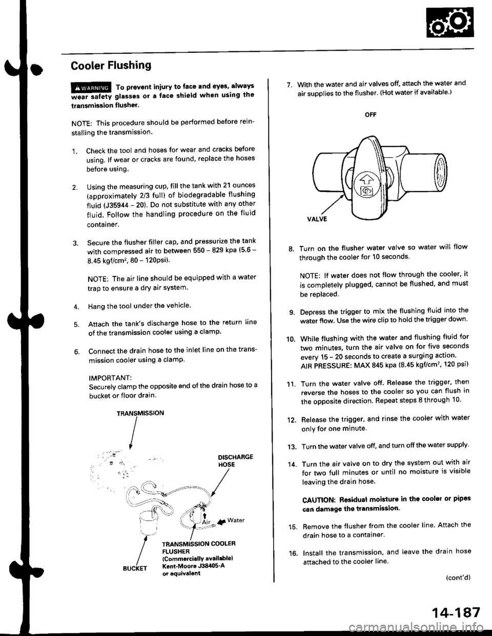
!!!@ To prevent iniury to. face and eyas, always
-ea. safetv glasses ot a face shield when using the
transmission flusher.
NOTE: This procedure should be performed before rein-
stalling the transmission.
1. Check the tool and hoses for wear and cracks before
using. lf wear or cracks are found, replace the hoses
before using.
Using the measuring cup, fill the tank with 2'l ounces
(approximately 2/3 full) of biodegradable flushing
fluid (J35944 - 20). Do not substitute with any other
fluid. Follow the handling procedure on the fluid
contarner.
Secure the flusher filler cap, and pressurize the tank
with compressed air to between 550 - 829 kpa (5 6 -
8.45 kgflcm'�. 80 - 120Psi).
NOTE: The air line should be equipped with a water
trap to ensure a dry air system.
Hang the tool under the vehicle.
Attach the tank's discharge hose to the return line
of the transmission cooler using a clamp.
Connect the drain hose to the inlet line on the trans-
mission cooler using a clamP
IMPORTANT:
Securely clamp the opposite end oJ the drain hose to a
bucket or floor drain.
TRAMtssroN
TRANSMISSION COOLERFLUSHER{Commcrci.llY avail.blel
Kent-Moore J384O5'Aor equivelent
NS
I
{r Water
7. With the water and air valves off, attach the water and
air suDolies to the flusher' lHot water if available.)
8, Turn on the flusher water valve so water will flow
through the cooler for 10 seconds.
NOTE; lf water does not tlow through the cooler, it
is completely plugged. cannot be flushed, and must
be replaced.
9. Depress the trigger to mix the flushing fluid into the
water flow. Use the wire clip to hold the trigger down'
While flushing with the water and flushing fluid for
two minutes, turn the air valve on for five seconds
everv 15 - 20 seconds to create a surging action'
AIR PRESSURE: MAX 845 kpa {8.45 kgf/cm'�, 120 psi)
Turn the water valve off. Release the trigger, then
reverse the hoses to the cooler so you can flush in
the opposite direction. Repeat steps 8 through 10'
12, Release the trigger, and rinse the cooler with water
onlv for one minute
13. Turn the water valve off, and turn off the water supply
14. Turn the air valve on to dry the system out with air
for two full minutes or until no moisture is visible
leaving the drain hose.
CAUTION: Residual mobturo in tho cooler or pipas
can damage the transmksion'
15. Remove the flusher from the cooler line. Attach the
drain hose to a contalner.
16. Install the transmission, and leave the drain hose
attached to the cooler line
{cont'd)
10.
'11.
14-187
Page 868 of 2189

Shift Cable
Adjustment
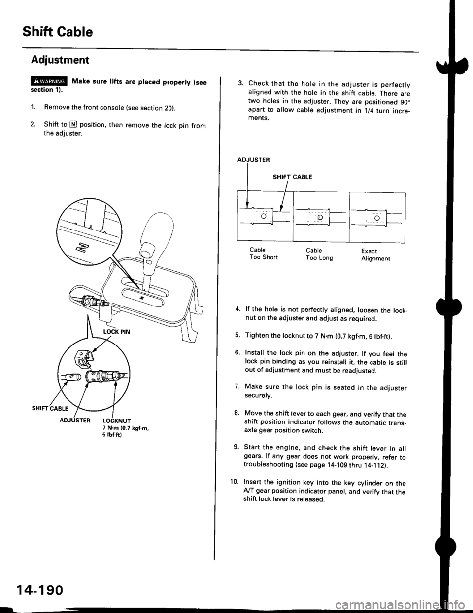
@ Make sure lifts are ptaced properly (see
section 1).
1. Remove the front console (see section Z0l.
2. Shift to @ position. then remove the lock pin fromthe adiuster.
7 N.m (0.75 tbtftlkgtm.
14-190
3. Check that the hole in the adjuster is perfectlyaligned with the hole in the shift cable. There aretwo holes in the adjuster. They are positioned 90.apart to allow cable adjustment in 1/4 turn incre-ments.
ExactAlignment
4. lf the hole is not perfectly aligned, loosen the lock-nut on the adjuster and adjust as required.
5. Tighten the tocknut to 7 N.m (0.7 kgf.m, 5 tbf.ft).
6. Install the lock pin on the adjuster. lf you feel thelock pin binding as you reinstall it, the cable is stillout of adjustment and must be readjusted.
7. Make sure the lock pin is seated in the adjustersecuretv.
8. Move the shift lever to each gear, and verify that theshift position indicator follows the automatic trans-axle gear position switch.
9. Start the engine, and check the shift lever in allgears. lf any gear does not work properly, refer totroubleshooting (see page 14-109 thru 1'4-'112).
10. Insert the ignition key into the key cylinder on theAy'T gear position indicator panel, and verify that theshift lock lever is released.
CableToo ShortCableToo Long
Page 873 of 2189

Description
The Continuously Variable Transmission (CVT) is an electronically controlled automatic transmission with drive and driv
en Oullevs, and a steel belt. The CVT provides non stage speeds forward and one reverse. The entire unit is positioned in
line with the engine.
Transmission
Around the outside of the flywheel is a ring gear which meshes with the starter pinion when the engine is being staned.
The transmission has four parallel shafts: the input shaft, the drive pulley shaft. the driven pulley shaft, and the secondary
gear shaft. The input shaft is in line with the engine crankshaft. The drive pulley shaft and the driven pulley shaft consist of
movable and fixed face pulleys. Both pulleys are linked by the steel belt.
The input shaft includes the sun gear. The drive pulley shaft includes the forward clutch which mounts the carrier assem-
bly on the forward clutch drum. The carrier assembly includes the pinion gears which mesh with the sun gear and the ring
gear. The ring gear has a hub-mounted reverse brake disc.
The driven pulley shaft includes the start clutch and the secondary drive gear which is integral with the park gear' The sec-
ondary gear shaft is positioned between the secondary drive gear and the final driven gear. The secondary gear shaft
includes the secondary driven gear which serves to change the rotation direction. because the drive pulley shaft and the
driven oullev shaft rotate the same direction. When certain combinations of planetary gears in the transmission are
engaged by the clutches and the reverse brake, power is transmitted from the drive pulley shaft to the driven pulley shaft
to provide E, E, E, and El.
Electronic Control'96 - 98 Models:
The electronic control system consists of the Transmission Control Module (TCM), sensors, three linear solenoids, and a
inhibitor solenoid. Shifting is electronically controlled under all conditions'
The TCM is located below the dashboard, behind the kick panel on the driver's side.'99 - 00 Models:
The electronic control svstem consists of a Powertrain Control Module (PCM), sensors, three linear solenoids and an
inhibitor solenoid. Shifting is electronically controlled under all conditions. A Grade Logic Control System to control shift-
ing in E position while the vehicle is ascending or descending a slope.
The PCM is located below the dashboard, under the kick panel on the passenger's side.
Hydraulic Control
The lower valve body assembly includes the main valve body, the Pressure Low (PL) reguiator valve body, the shift valve
body, the start clutch control valve body, and the secondary valve body. They are positioned on the lower part of the
transmission housing.
The main valve body contains the Pressure High (PH) control valve, the lubrication valve, and the pitot regulator valve.
The secondary valve body contains the PH regulator valve, the clutch reducing valve, the start clutch valve accumulator,
and the shift inhibitor valve. The PL regulator valve body contains the PL regulator valve and the PH-PL control valve
which is ioined to the PH,PL control linear solenoid. The inhibitor solenoid valve is bolted on the PL regulator valve body.
The shift valve body contains the shift valve and the shift control valve. which is joined to the shift control linear solenoid.
The start clutch control valve body contains the start clutch control valve, which is joined to the start clutch control linear
solenoid. The linear solenoids and the inhibitor solenoid are controlled by the TCM or PCM. The manual valve body which
contains the manual valve and the reverse inhibitor valve, is bolted on the intermediate housing.
The ATF pump assembly is located on the transmission housing, and is linked with the input shaft by the sprockets and
the sprocket chain. The pulleys and the clutch receive fluid from their respective feed pipes, and the reverse brake receives
fluid from internal hydraulic circuit.
Shift Control Mechanism
Input from various sensors located throughout the vehicle determines which linear solenoid the TCM or PCM will activate.
Activating the shift control linear solenoid changes the shift control valve pressure, causing the shift valve to move. This
pressurizes the drive pulley pressure to the drive pulley and the driven pulley pressure to the driven pulley and changes
their effective pulley ratio. Activating the start clutch control linear solenoid moves the start clutch control valve. The start
clutch control valve uncovers the port, providing pressure to the start clutch to engage it(cont'd)
14-195
,!