1996 CHRYSLER VOYAGER oil temperature
[x] Cancel search: oil temperaturePage 1226 of 1938
ENGINE OIL CHANGE
WARNING: NEW OR USED ENGINE OIL CAN BE
IRRITATING TO THE SKIN. AVOID PROLONGED OR
REPEATED SKIN CONTACT WITH ENGINE OIL.
CONTAMINANTS IN USED ENGINE OIL, CAUSED BY
INTERNAL COMBUSTION, CAN BE HAZARDOUS TO
YOUR HEALTH. THOROUGHLY WASH EXPOSED
SKIN WITH SOAP AND WATER. DO NOT WASH
SKIN WITH GASOLINE, DIESEL FUEL, THINNER, OR
SOLVENTS, HEALTH PROBLEMS CAN RESULT. DO
NOT POLLUTE, DISPOSE OF USED ENGINE OIL
PROPERLY. CONTACT YOUR DEALER OR GOVERN-
MENT AGENCY FOR LOCATION OF COLLECTION
CENTER IN YOUR AREA.
Run engine until achieving normal operating tem-
perature.
(1) Position the vehicle on a level surface and turn
engine off.
(2) Remove oil fill cap.
(3) Hoist vehicle. Refer to Hoisting and Jacking
Recommendations.
(4) Place a suitable drain pan under crankcase
drain.
(5) Remove drain plug from crankcase and allow
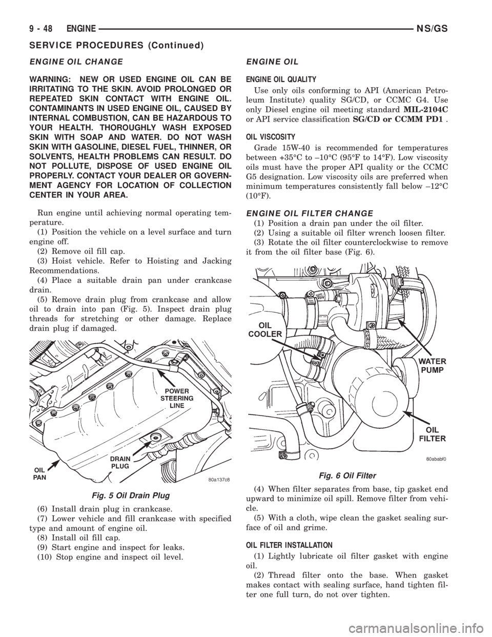
oil to drain into pan (Fig. 5). Inspect drain plug
threads for stretching or other damage. Replace
drain plug if damaged.
(6) Install drain plug in crankcase.
(7) Lower vehicle and fill crankcase with specified
type and amount of engine oil.
(8) Install oil fill cap.
(9) Start engine and inspect for leaks.
(10) Stop engine and inspect oil level.
ENGINE OIL
ENGINE OIL QUALITY
Use only oils conforming to API (American Petro-
leum Institute) quality SG/CD, or CCMC G4. Use
only Diesel engine oil meeting standardMIL-2104C
or API service classificationSG/CD or CCMM PD1.
OIL VISCOSITY
Grade 15W-40 is recommended for temperatures
between +35ÉC to ±10ÉC (95ÉF to 14ÉF). Low viscosity
oils must have the proper API quality or the CCMC
G5 designation. Low viscosity oils are preferred when
minimum temperatures consistently fall below ±12ÉC
(10ÉF).
ENGINE OIL FILTER CHANGE
(1) Position a drain pan under the oil filter.
(2) Using a suitable oil filter wrench loosen filter.
(3) Rotate the oil filter counterclockwise to remove
it from the oil filter base (Fig. 6).
(4) When filter separates from base, tip gasket end
upward to minimize oil spill. Remove filter from vehi-
cle.
(5) With a cloth, wipe clean the gasket sealing sur-
face of oil and grime.
OIL FILTER INSTALLATION
(1) Lightly lubricate oil filter gasket with engine
oil.
(2) Thread filter onto the base. When gasket
makes contact with sealing surface, hand tighten fil-
ter one full turn, do not over tighten.
Fig. 5 Oil Drain Plug
Fig. 6 Oil Filter
9 - 48 ENGINENS/GS
SERVICE PROCEDURES (Continued)
Page 1231 of 1938
ENGINE ASSEMBLY
REMOVAL
(1) Disconnect the battery.
(2) Remove the air cleaner assembly and inlet
hose.
(3) Remove both hoses at intercooler and engine.
(4) Disconnect EGR vacuum hose.
(5) Disconnect brake booster vacuum hose.
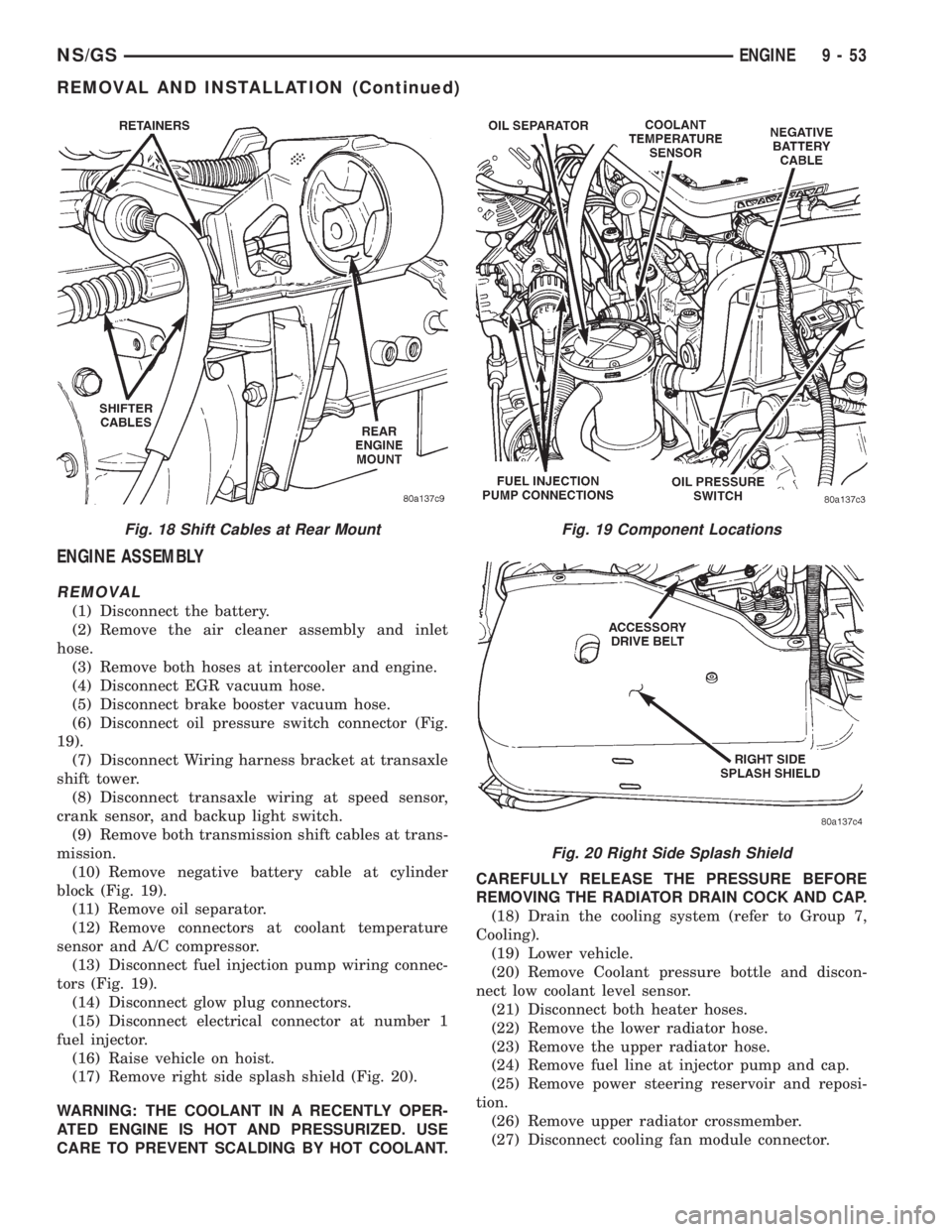
(6) Disconnect oil pressure switch connector (Fig.
19).
(7) Disconnect Wiring harness bracket at transaxle
shift tower.
(8) Disconnect transaxle wiring at speed sensor,
crank sensor, and backup light switch.
(9) Remove both transmission shift cables at trans-
mission.
(10) Remove negative battery cable at cylinder
block (Fig. 19).
(11) Remove oil separator.
(12) Remove connectors at coolant temperature
sensor and A/C compressor.
(13) Disconnect fuel injection pump wiring connec-
tors (Fig. 19).
(14) Disconnect glow plug connectors.
(15) Disconnect electrical connector at number 1
fuel injector.
(16) Raise vehicle on hoist.
(17) Remove right side splash shield (Fig. 20).
WARNING: THE COOLANT IN A RECENTLY OPER-
ATED ENGINE IS HOT AND PRESSURIZED. USE
CARE TO PREVENT SCALDING BY HOT COOLANT.CAREFULLY RELEASE THE PRESSURE BEFORE
REMOVING THE RADIATOR DRAIN COCK AND CAP.
(18) Drain the cooling system (refer to Group 7,
Cooling).
(19) Lower vehicle.
(20) Remove Coolant pressure bottle and discon-
nect low coolant level sensor.
(21) Disconnect both heater hoses.
(22) Remove the lower radiator hose.
(23) Remove the upper radiator hose.
(24) Remove fuel line at injector pump and cap.
(25) Remove power steering reservoir and reposi-
tion.
(26) Remove upper radiator crossmember.
(27) Disconnect cooling fan module connector.
Fig. 18 Shift Cables at Rear MountFig. 19 Component Locations
Fig. 20 Right Side Splash Shield
NS/GSENGINE 9 - 53
REMOVAL AND INSTALLATION (Continued)
Page 1237 of 1938
70É using angle torque tool. Then rotate the bolts an
additional 70É following tightening sequence.
(10) Then, tighten the 14mm bolts with special
tool VM-1018 in the following manner:
(11) Side bolts (M1-M2): Tighten M1 bolts to 30
N´m, then rotate them 85É (65). Tighten M2 bolts to
30 N´m, then rotate them 85É (65).
(12)2nd Phase:After 20 minutes of engine oper-
ation at operating temperature, allow engine to cool
down completely. Then retorque the head bolts as fol-
lows:
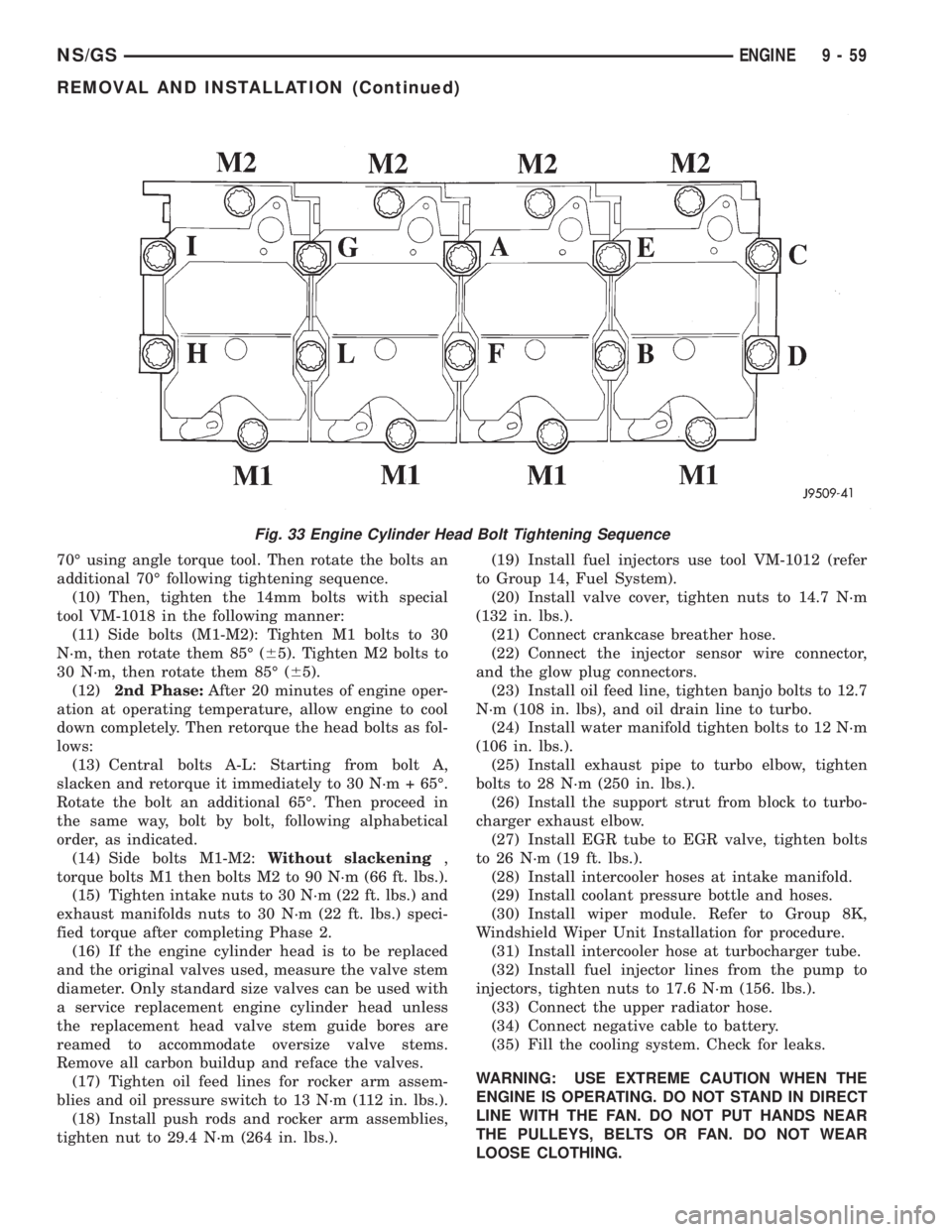
(13) Central bolts A-L: Starting from bolt A,
slacken and retorque it immediately to 30 N´m + 65É.
Rotate the bolt an additional 65É. Then proceed in
the same way, bolt by bolt, following alphabetical
order, as indicated.
(14) Side bolts M1-M2:Without slackening,
torque bolts M1 then bolts M2 to 90 N´m (66 ft. lbs.).
(15) Tighten intake nuts to 30 N´m (22 ft. lbs.) and
exhaust manifolds nuts to 30 N´m (22 ft. lbs.) speci-
fied torque after completing Phase 2.
(16) If the engine cylinder head is to be replaced
and the original valves used, measure the valve stem
diameter. Only standard size valves can be used with
a service replacement engine cylinder head unless
the replacement head valve stem guide bores are
reamed to accommodate oversize valve stems.
Remove all carbon buildup and reface the valves.
(17) Tighten oil feed lines for rocker arm assem-
blies and oil pressure switch to 13 N´m (112 in. lbs.).
(18) Install push rods and rocker arm assemblies,
tighten nut to 29.4 N´m (264 in. lbs.).(19) Install fuel injectors use tool VM-1012 (refer
to Group 14, Fuel System).
(20) Install valve cover, tighten nuts to 14.7 N´m
(132 in. lbs.).
(21) Connect crankcase breather hose.
(22) Connect the injector sensor wire connector,
and the glow plug connectors.
(23) Install oil feed line, tighten banjo bolts to 12.7
N´m (108 in. lbs), and oil drain line to turbo.
(24) Install water manifold tighten bolts to 12 N´m
(106 in. lbs.).
(25) Install exhaust pipe to turbo elbow, tighten
bolts to 28 N´m (250 in. lbs.).
(26) Install the support strut from block to turbo-
charger exhaust elbow.
(27) Install EGR tube to EGR valve, tighten bolts
to 26 N´m (19 ft. lbs.).
(28) Install intercooler hoses at intake manifold.
(29) Install coolant pressure bottle and hoses.
(30) Install wiper module. Refer to Group 8K,
Windshield Wiper Unit Installation for procedure.
(31) Install intercooler hose at turbocharger tube.
(32) Install fuel injector lines from the pump to
injectors, tighten nuts to 17.6 N´m (156. lbs.).
(33) Connect the upper radiator hose.
(34) Connect negative cable to battery.
(35) Fill the cooling system. Check for leaks.
WARNING: USE EXTREME CAUTION WHEN THE
ENGINE IS OPERATING. DO NOT STAND IN DIRECT
LINE WITH THE FAN. DO NOT PUT HANDS NEAR
THE PULLEYS, BELTS OR FAN. DO NOT WEAR
LOOSE CLOTHING.
Fig. 33 Engine Cylinder Head Bolt Tightening Sequence
NS/GSENGINE 9 - 59
REMOVAL AND INSTALLATION (Continued)
Page 1239 of 1938
(3) Install cylinder head, intake manifold, and
exhaust manifold. Refer to cylinder head installation
in this section.
(4) Install push rods in original positions.
(5) Install rocker arms in original positions.
(6) Install cylinder head cover. Refer to cylinder
valve cover installation in this section.
(7) Start and operate engine. Warm up to normal
operating temperature.
CAUTION: To prevent damage to valve mechanism,
engine must not be run above fast idle until all
hydraulic tappets have filled with oil and have
become quiet.
VIBRATION DAMPER
REMOVAL
(1) Disconnect the battery cable.
(2) Raise vehicle on hoist.
(3) Remove right side lower splash shield.
(4) Remove generator, power steering belt. Refer to
Group 7, Cooling.
(5) Remove water pump belt. Refer to Group 7,
Cooling.
(6) Remove engine starter. Refer to Group, 8B for
procedure
(7) Install flywheel locking tool VM.1014 to pre-
vent engine rotation.
NOTE: Crankshaft damper nut is left handed
thread.
(8) Remove vibration damper nut.
(9) Remove vibration damper. No special tool is
needed for removal.
CAUTION: If thread sealant is used it is important
to remove all the old thread sealant from the
threads on the crankshaft.
INSTALLATION
NOTE: Before installing damper be sure the O-ring
inside the center of the damper is in its grove.
(1) Install vibration damper.
CAUTION: Correct torque on the vibration damper
nut is important or engine damage can occur.
(2) Install vibration damper nut and tighten to 441
N´m (325 ft. lbs.).
(3) Remove flywheel locking tool, and install
engine starter.(4) Install both accessary drive belts. Refer to
Group 7, Cooling.
(5) Install right splash shield.
(6) Lower vehicle.
(7) Connect the battery cable.
TIMING GEAR COVER OIL SEAL
REMOVAL
(1) Disconnect the battery cable.
(2) Remove vibration damper. Refer to vibration
damper removal in this section.
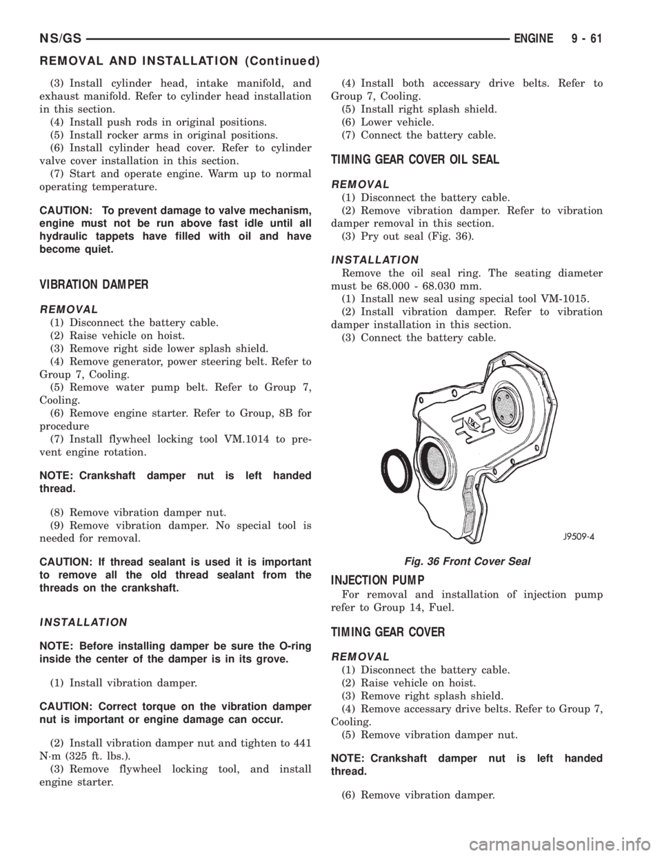
(3) Pry out seal (Fig. 36).
INSTALLATION
Remove the oil seal ring. The seating diameter
must be 68.000 - 68.030 mm.
(1) Install new seal using special tool VM-1015.
(2) Install vibration damper. Refer to vibration
damper installation in this section.
(3) Connect the battery cable.
INJECTION PUMP
For removal and installation of injection pump
refer to Group 14, Fuel.
TIMING GEAR COVER
REMOVAL
(1) Disconnect the battery cable.
(2) Raise vehicle on hoist.
(3) Remove right splash shield.
(4) Remove accessary drive belts. Refer to Group 7,
Cooling.
(5) Remove vibration damper nut.
NOTE: Crankshaft damper nut is left handed
thread.
(6) Remove vibration damper.
Fig. 36 Front Cover Seal
NS/GSENGINE 9 - 61
REMOVAL AND INSTALLATION (Continued)
Page 1271 of 1938
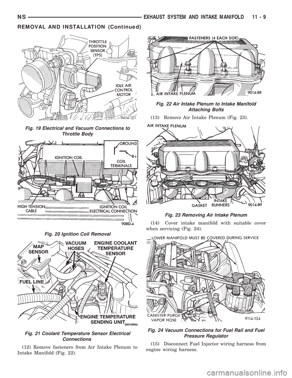
(12) Remove fasteners from Air Intake Plenum to
Intake Manifold (Fig. 22).(13) Remove Air Intake Plenum (Fig. 23).
(14) Cover intake manifold with suitable cover
when servicing (Fig. 24).
(15) Disconnect Fuel Injector wiring harness from
engine wiring harness.
Fig. 19 Electrical and Vacuum Connections to
Throttle Body
Fig. 20 Ignition Coil Removal
Fig. 21 Coolant Temperature Sensor Electrical
Connections
Fig. 22 Air Intake Plenum to Intake Manifold
Attaching Bolts
Fig. 23 Removing Air Intake Plenum
Fig. 24 Vacuum Connections for Fuel Rail and Fuel
Pressure Regulator
NSEXHAUST SYSTEM AND INTAKE MANIFOLD 11 - 9
REMOVAL AND INSTALLATION (Continued)
Page 1277 of 1938
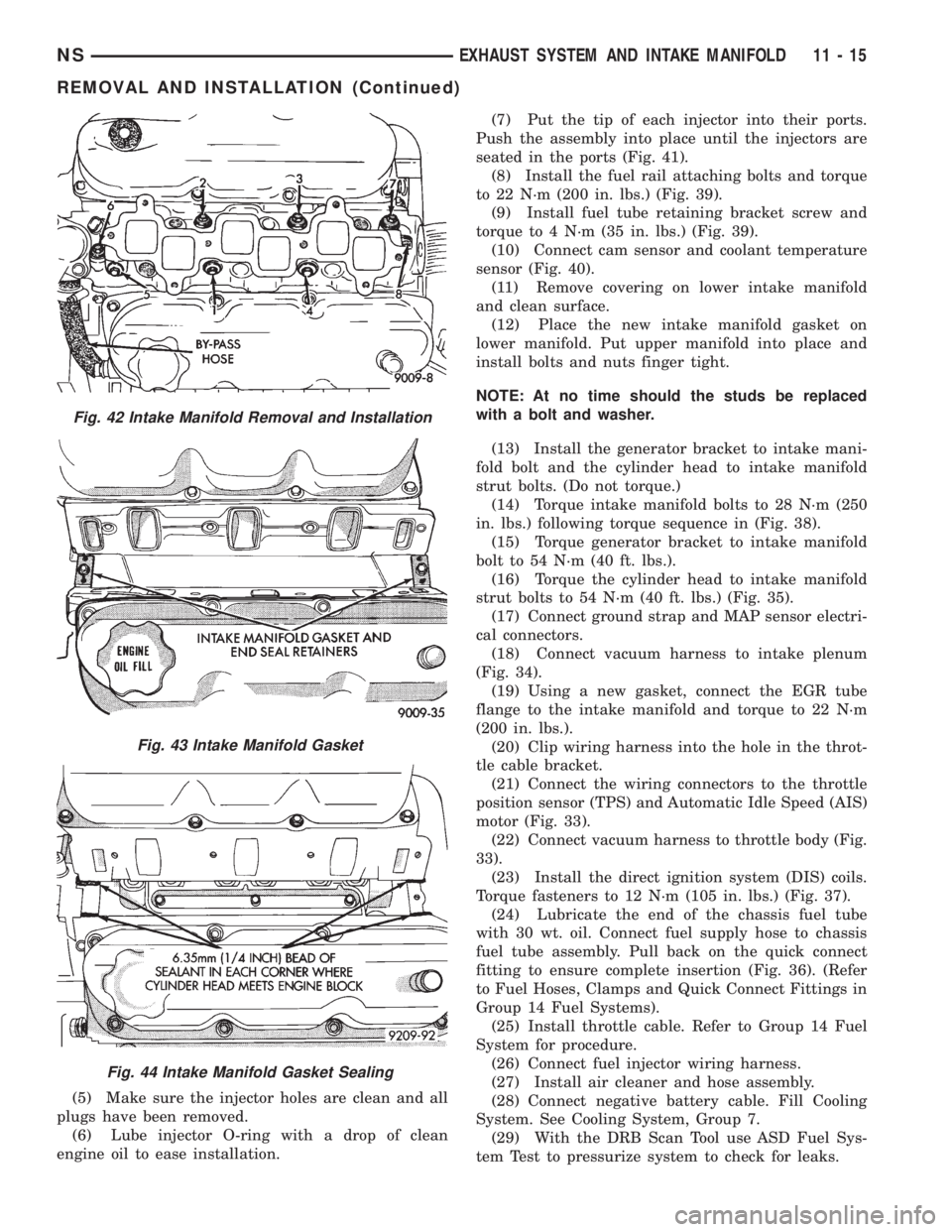
(5) Make sure the injector holes are clean and all
plugs have been removed.
(6) Lube injector O-ring with a drop of clean
engine oil to ease installation.(7) Put the tip of each injector into their ports.
Push the assembly into place until the injectors are
seated in the ports (Fig. 41).
(8) Install the fuel rail attaching bolts and torque
to 22 N´m (200 in. lbs.) (Fig. 39).
(9) Install fuel tube retaining bracket screw and
torque to 4 N´m (35 in. lbs.) (Fig. 39).
(10) Connect cam sensor and coolant temperature
sensor (Fig. 40).
(11) Remove covering on lower intake manifold
and clean surface.
(12) Place the new intake manifold gasket on
lower manifold. Put upper manifold into place and
install bolts and nuts finger tight.
NOTE: At no time should the studs be replaced
with a bolt and washer.
(13) Install the generator bracket to intake mani-
fold bolt and the cylinder head to intake manifold
strut bolts. (Do not torque.)
(14) Torque intake manifold bolts to 28 N´m (250
in. lbs.) following torque sequence in (Fig. 38).
(15) Torque generator bracket to intake manifold
bolt to 54 N´m (40 ft. lbs.).
(16) Torque the cylinder head to intake manifold
strut bolts to 54 N´m (40 ft. lbs.) (Fig. 35).
(17) Connect ground strap and MAP sensor electri-
cal connectors.
(18) Connect vacuum harness to intake plenum
(Fig. 34).
(19) Using a new gasket, connect the EGR tube
flange to the intake manifold and torque to 22 N´m
(200 in. lbs.).
(20) Clip wiring harness into the hole in the throt-
tle cable bracket.
(21) Connect the wiring connectors to the throttle
position sensor (TPS) and Automatic Idle Speed (AIS)
motor (Fig. 33).
(22) Connect vacuum harness to throttle body (Fig.
33).
(23) Install the direct ignition system (DIS) coils.
Torque fasteners to 12 N´m (105 in. lbs.) (Fig. 37).
(24) Lubricate the end of the chassis fuel tube
with 30 wt. oil. Connect fuel supply hose to chassis
fuel tube assembly. Pull back on the quick connect
fitting to ensure complete insertion (Fig. 36). (Refer
to Fuel Hoses, Clamps and Quick Connect Fittings in
Group 14 Fuel Systems).
(25) Install throttle cable. Refer to Group 14 Fuel
System for procedure.
(26) Connect fuel injector wiring harness.
(27) Install air cleaner and hose assembly.
(28) Connect negative battery cable. Fill Cooling
System. See Cooling System, Group 7.
(29) With the DRB Scan Tool use ASD Fuel Sys-
tem Test to pressurize system to check for leaks.
Fig. 42 Intake Manifold Removal and Installation
Fig. 43 Intake Manifold Gasket
Fig. 44 Intake Manifold Gasket Sealing
NSEXHAUST SYSTEM AND INTAKE MANIFOLD 11 - 15
REMOVAL AND INSTALLATION (Continued)
Page 1312 of 1938
INSTALLATION
(1) Position fuel tank on transmission jack. Con-
nect pressure relief/rollover valve hose. Connect fuel
filler tube vent hose and replace clamp.
(2) Raise tank into position and carefully work
filler tube into tank. A light coating of clean engine
oil on the tube end may be used to aid assembly.
(3) Feed filler vent line thru frame rail. Careful
not to cross lines.
(4) Tighten strap bolts to 54 N´m (40 ft. lbs.)
torque. Remove transmission jack.
(5) Tighten filler hose clamp to 3.3 N´m (30 in.
lbs.).
CAUTION: Ensure straps are not twisted or bent
before or after tightening strap nuts.
(6) Connect fuel pump/module electrical connector.
Place retainer in locked position.
(7) Lubricate the fuel supply line with clean 30
weight engine oil, install the quick connect fuel fit-
ting. Refer to Tube/Fitting Assembly in the Fuel
Delivery section of this Group.
(8) Attach filler line to filler tube. Pull on connec-
tor to make sure of connection.
(9) Fill fuel tank, replace cap, and connect battery
negative cable.
CAUTION: When using the ASD Fuel System Test,
the ASD relay and fuel pump relay remain energized
for 7 minutes or until the test is stopped, or until
the ignition switch is turned to the Off position.
(10) Use the DRB scan tool ASD Fuel System Test
to pressurize the fuel system. Check for leaks.
FUEL INJECTOR RAILÐ2.4L
REMOVAL
(1) Perform fuel system pressure release procedure
before servicing or starting repairs.Refer to
Fuel System Pressure Release Procedure in this sec-
tion.
(2) Disconnect negative cable from battery.
(3) Remove air cleaner inlet hose from throttle
body.
(4) Remove throttle cable and speed control cable
(if equipped) from throttle lever.
(5) Remove throttle cables from bracket by com-
pressing retaining tabs.
(6) Remove connector from throttle position sensor.
(7) Remove connector from idle air control motor.
(8) Remove vacuum lines from intake plenum fit-
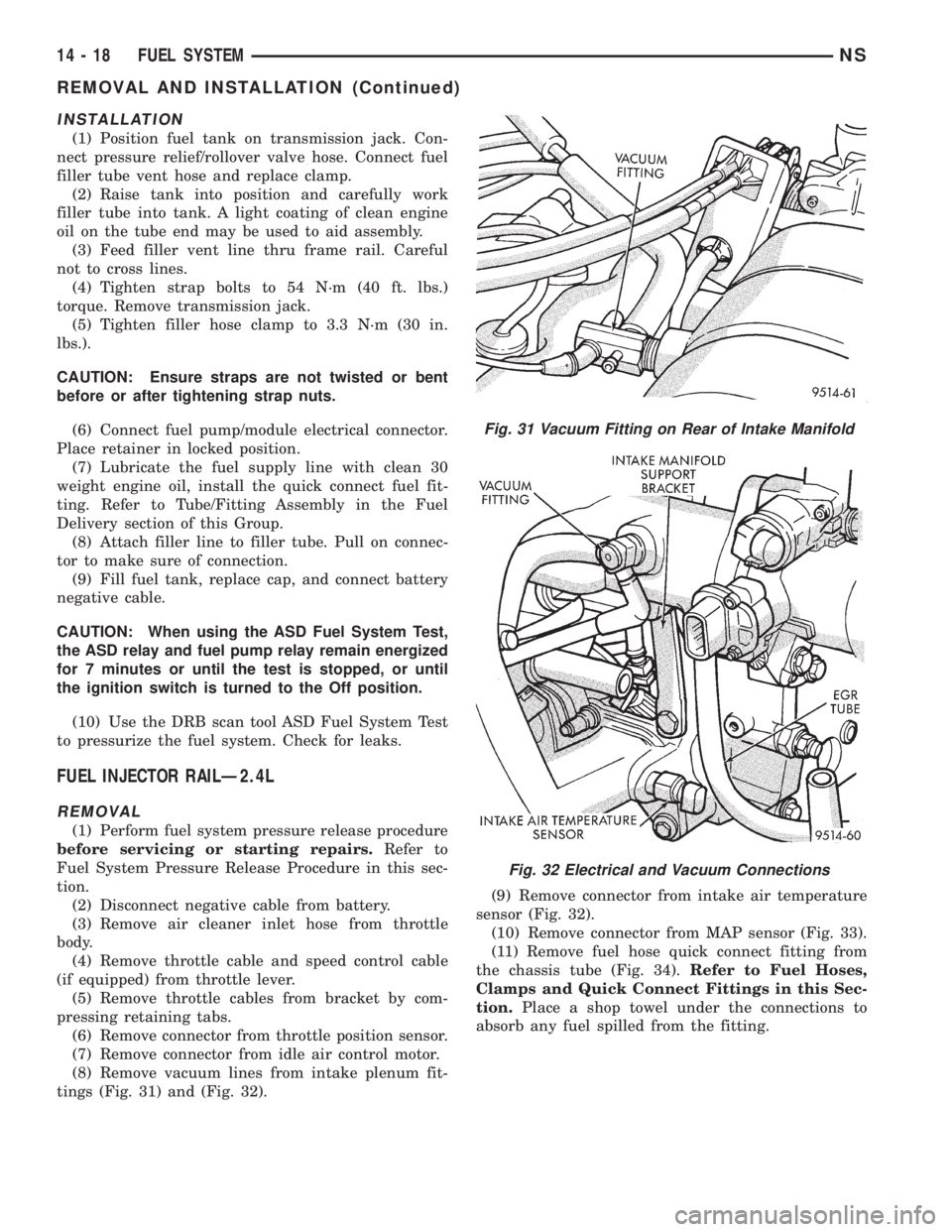
tings (Fig. 31) and (Fig. 32).(9) Remove connector from intake air temperature
sensor (Fig. 32).
(10) Remove connector from MAP sensor (Fig. 33).
(11) Remove fuel hose quick connect fitting from
the chassis tube (Fig. 34).Refer to Fuel Hoses,
Clamps and Quick Connect Fittings in this Sec-
tion.Place a shop towel under the connections to
absorb any fuel spilled from the fitting.
Fig. 31 Vacuum Fitting on Rear of Intake Manifold
Fig. 32 Electrical and Vacuum Connections
14 - 18 FUEL SYSTEMNS
REMOVAL AND INSTALLATION (Continued)
Page 1315 of 1938
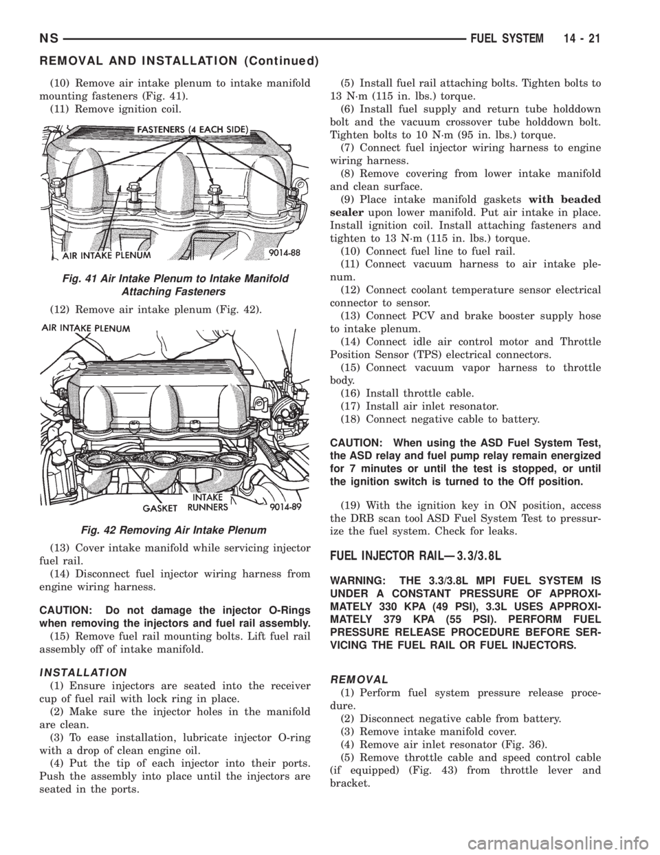
(10) Remove air intake plenum to intake manifold
mounting fasteners (Fig. 41).
(11) Remove ignition coil.
(12) Remove air intake plenum (Fig. 42).
(13) Cover intake manifold while servicing injector
fuel rail.
(14) Disconnect fuel injector wiring harness from
engine wiring harness.
CAUTION: Do not damage the injector O-Rings
when removing the injectors and fuel rail assembly.
(15) Remove fuel rail mounting bolts. Lift fuel rail
assembly off of intake manifold.
INSTALLATION
(1) Ensure injectors are seated into the receiver
cup of fuel rail with lock ring in place.
(2) Make sure the injector holes in the manifold
are clean.
(3) To ease installation, lubricate injector O-ring
with a drop of clean engine oil.
(4) Put the tip of each injector into their ports.
Push the assembly into place until the injectors are
seated in the ports.(5) Install fuel rail attaching bolts. Tighten bolts to
13 N´m (115 in. lbs.) torque.
(6) Install fuel supply and return tube holddown
bolt and the vacuum crossover tube holddown bolt.
Tighten bolts to 10 N´m (95 in. lbs.) torque.
(7) Connect fuel injector wiring harness to engine
wiring harness.
(8) Remove covering from lower intake manifold
and clean surface.
(9) Place intake manifold gasketswith beaded
sealerupon lower manifold. Put air intake in place.
Install ignition coil. Install attaching fasteners and
tighten to 13 N´m (115 in. lbs.) torque.
(10) Connect fuel line to fuel rail.
(11) Connect vacuum harness to air intake ple-
num.
(12) Connect coolant temperature sensor electrical
connector to sensor.
(13) Connect PCV and brake booster supply hose
to intake plenum.
(14) Connect idle air control motor and Throttle
Position Sensor (TPS) electrical connectors.
(15) Connect vacuum vapor harness to throttle
body.
(16) Install throttle cable.
(17) Install air inlet resonator.
(18) Connect negative cable to battery.
CAUTION: When using the ASD Fuel System Test,
the ASD relay and fuel pump relay remain energized
for 7 minutes or until the test is stopped, or until
the ignition switch is turned to the Off position.
(19) With the ignition key in ON position, access
the DRB scan tool ASD Fuel System Test to pressur-
ize the fuel system. Check for leaks.
FUEL INJECTOR RAILÐ3.3/3.8L
WARNING: THE 3.3/3.8L MPI FUEL SYSTEM IS
UNDER A CONSTANT PRESSURE OF APPROXI-
MATELY 330 KPA (49 PSI), 3.3L USES APPROXI-
MATELY 379 KPA (55 PSI). PERFORM FUEL
PRESSURE RELEASE PROCEDURE BEFORE SER-
VICING THE FUEL RAIL OR FUEL INJECTORS.
REMOVAL
(1) Perform fuel system pressure release proce-
dure.
(2) Disconnect negative cable from battery.
(3) Remove intake manifold cover.
(4) Remove air inlet resonator (Fig. 36).
(5) Remove throttle cable and speed control cable
(if equipped) (Fig. 43) from throttle lever and
bracket.
Fig. 41 Air Intake Plenum to Intake Manifold
Attaching Fasteners
Fig. 42 Removing Air Intake Plenum
NSFUEL SYSTEM 14 - 21
REMOVAL AND INSTALLATION (Continued)