1996 CHRYSLER VOYAGER oil temperature
[x] Cancel search: oil temperaturePage 1057 of 1938
ENGINE DIAGNOSIS
INDEX
page page
DIAGNOSIS AND TESTING
CYLINDER COMBUSTION
PRESSURE LEAKAGE TEST.............. 8
CYLINDER COMPRESSION PRESSURE TEST . . 7
ENGINE DIAGNOSISÐMECHANICAL......... 12
ENGINE DIAGNOSISÐPERFORMANCE...... 10GENERAL INFORMATION.................. 7
INSPECTION
(ENGINE OIL LEAKS IN GENERAL)......... 8
INTAKE MANIFOLD LEAKAGE DIAGNOSIS..... 7
LASH ADJUSTER (TAPPET)
NOISE DIAGNOSIS...................... 8
DIAGNOSIS AND TESTING
GENERAL INFORMATION
Engine diagnosis is helpful in determining the
causes of malfunctions.
These malfunctions may be classified as either
mechanical (e.g., a strange noise), or performance
(e.g., engine idles rough and stalls).
Refer to the Service DiagnosisÐMechanical Chart
and the Service DiagnosisÐPerformance Chart, for
possible causes and corrections of malfunctions. Refer
to Group 14, Fuel System, for the fuel system diag-
nosis.
Additional tests and diagnostic procedures may be
necessary for specific engine malfunctions that can-
not be isolated with the Service Diagnosis charts.
Information concerning additional tests and diagno-
sis is provided within the following:
²Cylinder Compression Pressure Test
²Cylinder Combustion Pressure Leakage Test
²Engine Cylinder Head Gasket Failure Diagnosis
²Intake Manifold Leakage Diagnosis
INTAKE MANIFOLD LEAKAGE DIAGNOSIS
An intake manifold air leak is characterized by
lower than normal manifold vacuum. Also, one or
more cylinders may not be functioning.
WARNING: USE EXTREME CAUTION WHEN THE
ENGINE IS OPERATING. DO NOT STAND IN A
DIRECT LINE WITH THE FAN. DO NOT PUT YOUR
HANDS NEAR THE PULLEYS, BELTS OR THE FAN.
DO NOT WEAR LOOSE CLOTHING.
(1) Start the engine.
(2) Spray a small stream of water (Spray Bottle) at
the suspected leak area.
(3) If a change in RPM'S, the area of the suspected
leak has been found.
(4) Repair as required.
CYLINDER COMPRESSION PRESSURE TEST
The results of a cylinder compression pressure test
can be utilized to diagnose several engine malfunc-
tions.
Ensure the battery is completely charged and the
engine starter motor is in good operating condition.
Otherwise the indicated compression pressures may
not be valid for diagnosis purposes.
(1) Check engine oil level and add oil if necessary.
(2) Drive the vehicle until engine reaches normal
operating temperature. Select a route free from traf-
fic and other forms of congestion, observe all traffic
laws, and accelerate through the gears several times
briskly.
(3) Remove all spark plugs from engine. As spark
plugs are being removed, check electrodes for abnor-
mal firing indicators fouled, hot, oily, etc. Record cyl-
inder number of spark plug for future reference.
(4) Disconnect coil wire from distributor and
secure to good ground to prevent a spark from start-
ing a fire (Conventional Ignition System). For Direct
Ignition System DIS disconnect the coil connector.
(5) Be sure throttle blade is fully open during the
compression check.
(6) Insert compression gage adaptor into the #1
spark plug hole in cylinder head. Crank engine until
maximum pressure is reached on gage. Record this
pressure as #1 cylinder pressure.
(7) Repeat the previous step for all remaining cyl-
inders.
(8) Compression should not be less than (689kPa)
100 psi and not vary more than 25 percent from cyl-
inder to cylinder.
(9) If one or more cylinders have abnormally low
compression pressures, repeat the compression test.
(10) If the same cylinder or cylinders repeat an
abnormally low reading on the second compression
test, it could indicate the existence of a problem in
the cylinder in question.The recommended com-
pression pressures are to be used only as a
guide to diagnosing engine problems. An engine
should not be disassembled to determine the
NSENGINE 9 - 7
Page 1058 of 1938
cause of low compression unless some malfunc-
tion is present.
(11) Clean or replace spark plugs as necessary
and adjust gap as specified in Group 8, Electrical.
Tighten to specifications.
(12) Test resistance of spark plug cables. Refer to
Group 8, Electrical Ignition System Secondary Cir-
cuit Inspection.
(13) Test coil output voltage, primary and second-
ary resistance. Replace parts as necessary. Refer to
Group 8, Electrical Ignition System.
(14) Check fuel pump pressure at idle and differ-
ent RPM ranges. Refer to Group 14, Fuel System for
Specifications.
(15) The air filter elements should be replaced as
specified in Group 0, Lubrication and Maintenance,.
(16) Inspect crankcase ventilation system as out
lined in Group 0, Lubrication and Maintenance. For
emission controls see Group 25, Emission Controls
for service procedures.
(17) Inspect and adjust accessory belt drives refer-
ring to Group 7, Cooling System, Accessory Drive
Belts for proper adjustments.
(18) Road test vehicle as a final test.
CYLINDER COMBUSTION PRESSURE LEAKAGE
TEST
The combustion pressure leakage test provides an
accurate means for determining engine condition.
Combustion pressure leakage testing will detect:
²Exhaust and intake valve leaks (improper seat-
ing).
²Leaks between adjacent cylinders or into water
jacket.
²Any causes for combustion/compression pressure
loss.
WARNING: DO NOT REMOVE THE RADIATOR CAP
WITH THE SYSTEM HOT AND UNDER PRESSURE
BECAUSE SERIOUS BURNS FROM COOLANT CAN
OCCUR.
Check the coolant level and fill as required. DO
NOT install the radiator cap.
Start and operate the engine until it attains nor-
mal operating temperature, then turn the engine
OFF.
Clean spark plug recesses with compressed air.
Remove the spark plugs.
Remove the oil filler cap.
Remove the air cleaner.
Calibrate the tester according to the manufactur-
er's instructions. The shop air source for testing
should maintain 483 kPa (70 psi) minimum, 1 379
kPa (200 psi) maximum and 552 kPa (80 psi) recom-
mended.Perform the test procedures on each cylinder
according to the tester manufacturer's instructions.
While testing, listen for pressurized air escaping
through the throttle body, tailpipe and oil filler cap
opening. Check for bubbles in the radiator coolant.
All gauge pressure indications should be equal,
with no more than 25% leakage.
FOR EXAMPLE:At 552 kPa (80 psi) input pres-
sure, a minimum of 414 kPa (60 psi) should be main-
tained in the cylinder.
LASH ADJUSTER (TAPPET) NOISE DIAGNOSIS
A tappet-like noise may be produced from several
items. Check the following items.
(1) Engine oil level too high or too low. This may
cause aerated oil to enter the adjusters and cause
them to be spongy.
(2) Insufficient running time after rebuilding cylin-
der head. Low speed running up to 1 hour may be
required.
(3) During this time, turn engine off and let set for
a few minutes before restarting. Repeat this several
times after engine has reached normal operating
temperature.
(4) Low oil pressure.
(5) The oil restrictor pressed into the vertical oil
passage to the cylinder head is plugged with debris.
(6) Air ingested into oil due to broken or cracked
oil pump pick up.
(7) Worn valve guides.
(8) Rocker arm ears contacting valve spring
retainer.
(9) Rocker arm loose, adjuster stuck or at maxi-
mum extension and still leaves lash in the system.
(10) Faulty lash adjuster.
a. Check lash adjusters for sponginess while
installed in cylinder head. Depress part of rocker
arm over adjuster. Normal adjusters should feel very
firm. Spongy adjusters can be bottomed out easily.
b. Remove suspected lash adjusters, and disassem-
bleDo not reuse retainer caps. Do not inter-
change parts and make sure that care and
cleanliness is exercised in the handling of parts.
c. Clean out dirt and varnish with solvent.
d. Reassemble with engine oil.
e. Check for sponginess.
f. If still spongy, replace with new adjuster.
INSPECTION (ENGINE OIL LEAKS IN GENERAL)
Begin with a through visual inspection of the
engine, particularly at the area of the suspected leak.
If an oil leak source is not readily identifiable, the
following steps should be followed:
(1) Do not clean or degrease the engine at this
time because some solvents may cause rubber to
swell, temporarily stopping the leak.
9 - 8 ENGINENS
DIAGNOSIS AND TESTING (Continued)
Page 1066 of 1938
sealing and a chrome plated taper faced intermediate
ring for additional cylinder pressure control. There
are also standard oil control rings.
CYLINDER HEAD:Features a Dual Over Head
Camshaft (DOHC) 4 valves per cylinder cross flow
design. The valves are arranged in two inline banks,
with the ports of the bank of two intake valves per
cylinder facing toward the radiator side of engine
and ports of the bank of two exhaust valves per cyl-
inder facing toward the dash panel. Incorporates
powder metal valve guides and seats. Integral oil gal-
leys within the cylinder head supplies oil to the
hydraulic lash adjusters, camshaft and valve mecha-
nisms.
CAMSHAFTS:The nodular iron camshafts have
six bearing journals and 2 cam lobes per cylinder.
Flanges at the rear journals control camshaft end
play. Provision for cam position sensor is located on
the intake camshaft at the rear of cylinder head. A
hydrodynamic oil seal is used for oil control at the
front of the camshaft.
VALVES:4 valves per cylinder are actuated by
roller cam followers which pivot on stationary
hydraulic lash adjusters. All valves have 6 mm diam-
eter chrome plated valve stems. The valve sizes are
34.8 mm (1.370 inch.) diameter intake valves and
30.5 mm (1.20 inch.) diameter exhaust valves. Viton
rubber valve stem seals are integral with the spring
seats. Valve springs, spring retainers, and locks are
conventional.
INTAKE MANIFOLD:The intake manifold is a
two piece aluminum casting, attached to the cylinder
head with ten screws. This long branch fan design
enhances low and midspeed torque, while minimizing
undesirable inlet noise.
EXHAUST MANIFOLD:The exhaust manifold is
made of cast iron for strength and high tempera-
tures.
ENGINE LUBRICATION:Refer to Group 0
Lubrication and Maintenance for recommended oil to
be used in various engine application. System is full
flow filtration, pressure feed type. The oil pump is
mounted in the front engine cover and driven by the
crankshaft. Pressurized oil is then routed through
the main oil gallery, running the length of the cylin-
der block, supplying main and rod bearings with fur-
ther routing. Pistons are lubricated from rod bearing
throw off and lubricating slots on the connecting rod
assemblies. Camshaft and valve mechanisms are
lubricated from a full length cylinder head oil gallery
supplied from the crankcase main oil gallery.DIAGNOSIS AND TESTING
CHECKING ENGINE OIL PRESSURE
(1) Remove oil pressure sending unit and install
gauge assembly C-3292.
(2) Run engine until thermostat opens.
CAUTION: If oil pressure is 0 at idle, Do Not Run
engine at 3000 RPM
(3) Oil Pressure:Curb Idle25 kPa (4 psi) mini-
mum3000 RPM170/550 kPa (25/80 psi).
(4) If oil pressure is 0 at idle. Shut off engine,
check for pressure relief valve stuck open or a
clogged oil pickup screen.
SERVICE PROCEDURES
FITTING PISTONS
Piston and cylinder wall must be clean and dry.
Piston diameter should be measured 90 degrees to
piston pin about 14 mm (9/16 inch.) from the bottom
of the skirt as shown in (Fig. 3). Cylinder bores
should be measured halfway down the cylinder bore
and transverse to the engine crankshaft center line
shown in (Fig. 2). Refer to Cylinder Bore and Piston
Specification Chart.
Correct piston to bore clearance must be estab-
lished in order to assure quiet and economical oper-
ation.
Chrysler engines use pistons designed specifically
for each engine model. Clearance and sizing locations
vary with respect to engine model.
NOTE: Pistons and cylinder bores should be mea-
sured at normal room temperature, 70ÉF (21ÉC).
FITTING PISTON RINGS
(1) Wipe cylinder bore clean. Insert ring and push
down with piston to ensure it is square in bore. The
ring gap measurement must be made with the ring
positioning at least 12 mm (0.50 inch) from bottom of
cylinder bore. Check gap with feeler gauge (Fig. 4).
Refer to specification in Piston Ring Specification
Chart.
(2) Check piston ring to groove side clearance (Fig.
5). Refer to specification in Piston Ring Specification
Chart.
9 - 16 2.4L ENGINENS
DESCRIPTION AND OPERATION (Continued)
Page 1145 of 1938
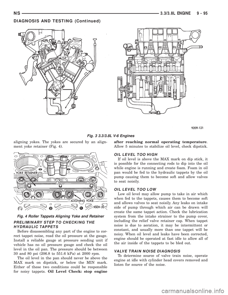
aligning yokes. The yokes are secured by an align-
ment yoke retainer (Fig. 4).
PRELIMINARY STEP TO CHECKING THE
HYDRAULIC TAPPETS
Before disassembling any part of the engine to cor-
rect tappet noise, read the oil pressure at the gauge.
Install a reliable gauge at pressure sending unit if
vehicle has no oil pressure gauge and check the oil
level in the oil pan. The pressure should be between
30 and 80 psi (206.8 to 551.6 kPa) at 2000 rpm.
The oil level in the pan should never be above the
MAX mark on dipstick, or below the MIN mark.
Either of these two conditions could be responsible
for noisy tappets.Oil Level Check: stop engineafter reaching normal operating temperature.
Allow 5 minutes to stabilize oil level, check dipstick.
OIL LEVEL TOO HIGH
If oil level is above the MAX mark on dip stick, it
is possible for the connecting rods to dip into the oil
while engine is running and create foam. Foam in oil
pan would be fed to the hydraulic tappets by the oil
pump causing them to become soft and allow valves
to seat noisily.
OIL LEVEL TOO LOW
Low oil level may allow pump to take in air which
when fed to the tappets, causes them to become soft
and allows valves to seat noisily. Any leaks on intake
side of pump through which air can be drawn will
create the same tappet action. Check the lubrication
system from the intake strainer to the pump cover,
including the relief valve retainer cap. When tappet
noise is due to aeration, it may be intermittent or
constant, and usually more than one tappet will be
noisy. When oil level and leaks have been corrected,
engine should be operated at fast idle to allow all of
the air inside of the tappets to be bled out.
VALVE TRAIN NOISE DIAGNOSIS
To determine source of valve train noise, operate
engine at idle with cylinder head covers removed and
listen for source of the noise.
Fig. 3 3.3/3.8L V-6 Engines
Fig. 4 Roller Tappets Aligning Yoke and Retainer
NS3.3/3.8L ENGINE 9 - 95
DIAGNOSIS AND TESTING (Continued)
Page 1161 of 1938
(6) Start and operate engine. Warm up to normal
operating temperature.
CAUTION: To prevent damage to valve mechanism,
engine must not be run above fast idle until all
hydraulic tappets have filled with oil and have
become quiet.
TIMING CHAIN COVER
REMOVAL
(1) Disconnect negative cable from battery.
(2) Drain cooling system. Refer to Cooling System
Group 7 for procedure.
(3) Support engine and remove right engine
mount.
(4) Raise vehicle on hoist. Drain engine oil.
(5) Remove oil pan and oil pump pick-up. It may
necessary to remove transaxle inspection cover.
(6) Remove right wheel and inner splash shield.
(7) Remove drive belt. Refer to Cooling System
Group 7 for procedure.
(8) Remove A/C compressor and set aside.
(9) Remove A/C compressor mounting bracket.
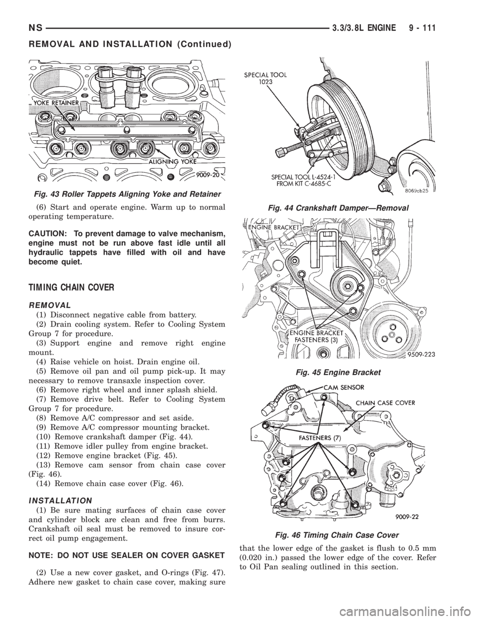
(10) Remove crankshaft damper (Fig. 44).
(11) Remove idler pulley from engine bracket.
(12) Remove engine bracket (Fig. 45).
(13) Remove cam sensor from chain case cover
(Fig. 46).
(14) Remove chain case cover (Fig. 46).
INSTALLATION
(1) Be sure mating surfaces of chain case cover
and cylinder block are clean and free from burrs.
Crankshaft oil seal must be removed to insure cor-
rect oil pump engagement.
NOTE: DO NOT USE SEALER ON COVER GASKET
(2) Use a new cover gasket, and O-rings (Fig. 47).
Adhere new gasket to chain case cover, making surethat the lower edge of the gasket is flush to 0.5 mm
(0.020 in.) passed the lower edge of the cover. Refer
to Oil Pan sealing outlined in this section.
Fig. 43 Roller Tappets Aligning Yoke and Retainer
Fig. 44 Crankshaft DamperÐRemoval
Fig. 45 Engine Bracket
Fig. 46 Timing Chain Case Cover
NS3.3/3.8L ENGINE 9 - 111
REMOVAL AND INSTALLATION (Continued)
Page 1176 of 1938
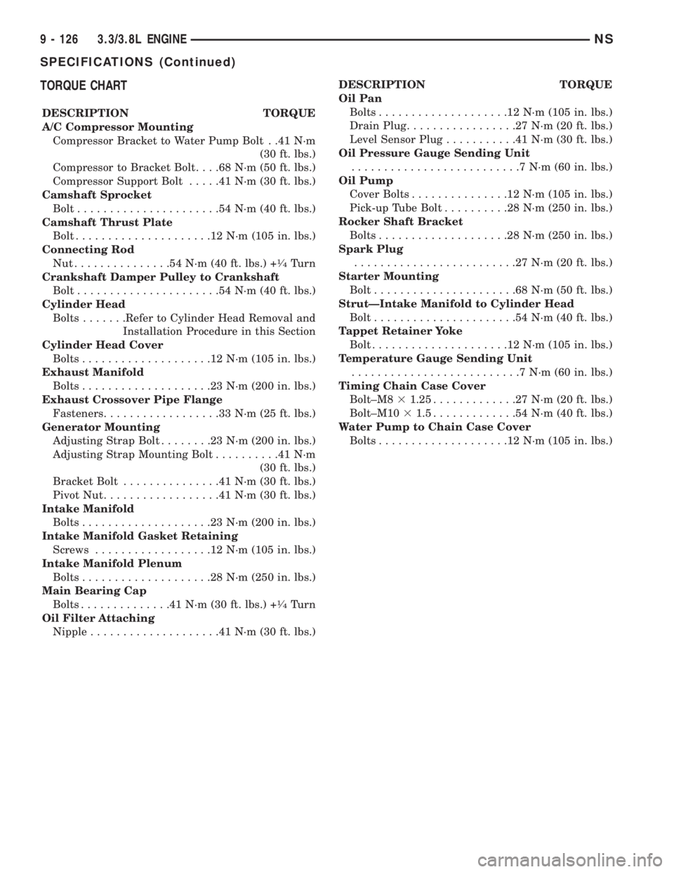
TORQUE CHART
DESCRIPTION TORQUE
A/C Compressor Mounting
Compressor Bracket to Water Pump Bolt . .41 N´m
(30 ft. lbs.)
Compressor to Bracket Bolt. . . .68 N´m (50 ft. lbs.)
Compressor Support Bolt.....41N´m(30ft.lbs.)
Camshaft Sprocket
Bolt......................54N´m(40ft.lbs.)
Camshaft Thrust Plate
Bolt.....................12N´m(105 in. lbs.)
Connecting Rod
Nut...............54N´m(40ft.lbs.) +
1¤4Turn
Crankshaft Damper Pulley to Crankshaft
Bolt......................54N´m(40ft.lbs.)
Cylinder Head
Bolts.......Refer to Cylinder Head Removal and
Installation Procedure in this Section
Cylinder Head Cover
Bolts....................12N´m(105 in. lbs.)
Exhaust Manifold
Bolts....................23N´m(200 in. lbs.)
Exhaust Crossover Pipe Flange
Fasteners..................33N´m(25ft.lbs.)
Generator Mounting
Adjusting Strap Bolt........23N´m(200 in. lbs.)
Adjusting Strap Mounting Bolt..........41N´m
(30 ft. lbs.)
Bracket Bolt...............41N´m(30ft.lbs.)
Pivot Nut..................41N´m(30ft.lbs.)
Intake Manifold
Bolts....................23N´m(200 in. lbs.)
Intake Manifold Gasket Retaining
Screws..................12N´m(105 in. lbs.)
Intake Manifold Plenum
Bolts....................28N´m(250 in. lbs.)
Main Bearing Cap
Bolts..............41N´m(30ft.lbs.) +
1¤4Turn
Oil Filter Attaching
Nipple....................41N´m(30ft.lbs.)DESCRIPTION TORQUE
Oil Pan
Bolts....................12N´m(105 in. lbs.)
Drain Plug.................27N´m(20ft.lbs.)
Level Sensor Plug...........41N´m(30ft.lbs.)
Oil Pressure Gauge Sending Unit
..........................7N´m(60in.lbs.)
Oil Pump
Cover Bolts...............12N´m(105 in. lbs.)
Pick-up Tube Bolt..........28N´m(250 in. lbs.)
Rocker Shaft Bracket
Bolts....................28N´m(250 in. lbs.)
Spark Plug
.........................27N´m(20ft.lbs.)
Starter Mounting
Bolt......................68N´m(50ft.lbs.)
StrutÐIntake Manifold to Cylinder Head
Bolt......................54N´m(40ft.lbs.)
Tappet Retainer Yoke
Bolt.....................12N´m(105 in. lbs.)
Temperature Gauge Sending Unit
..........................7N´m(60in.lbs.)
Timing Chain Case Cover
Bolt±M831.25.............27N´m(20ft.lbs.)
Bolt±M1031.5.............54N´m(40ft.lbs.)
Water Pump to Chain Case Cover
Bolts....................12N´m(105 in. lbs.)
9 - 126 3.3/3.8L ENGINENS
SPECIFICATIONS (Continued)
Page 1182 of 1938
(4) If oil pressure is 0 at idle. Shut off engine,
check for pressure relief valve stuck open, a clogged
oil pick-up screen or a damaged oil pick-up tube
O-ring.
SERVICE PROCEDURES
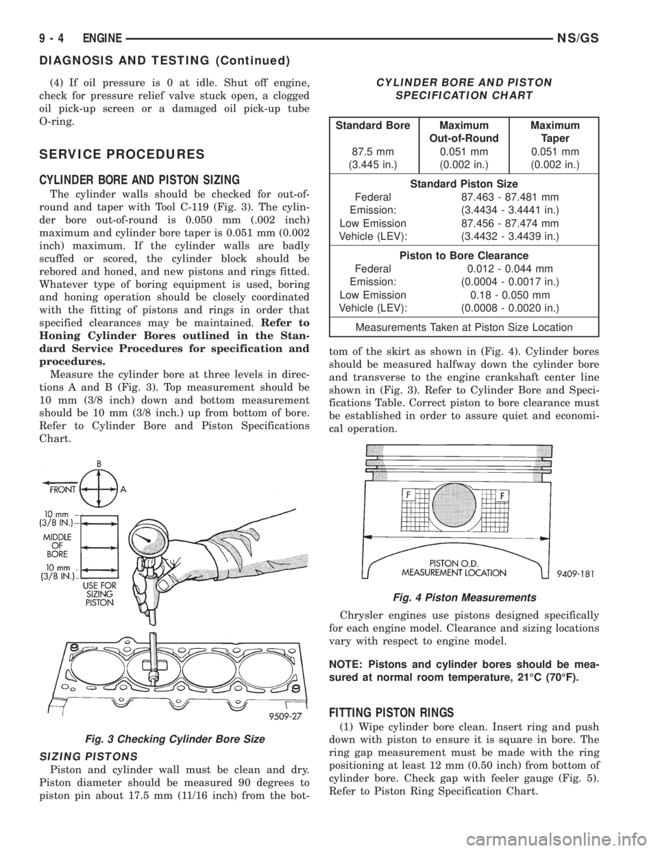
CYLINDER BORE AND PISTON SIZING
The cylinder walls should be checked for out-of-
round and taper with Tool C-119 (Fig. 3). The cylin-
der bore out-of-round is 0.050 mm (.002 inch)
maximum and cylinder bore taper is 0.051 mm (0.002
inch) maximum. If the cylinder walls are badly
scuffed or scored, the cylinder block should be
rebored and honed, and new pistons and rings fitted.
Whatever type of boring equipment is used, boring
and honing operation should be closely coordinated
with the fitting of pistons and rings in order that
specified clearances may be maintained.Refer to
Honing Cylinder Bores outlined in the Stan-
dard Service Procedures for specification and
procedures.
Measure the cylinder bore at three levels in direc-
tions A and B (Fig. 3). Top measurement should be
10 mm (3/8 inch) down and bottom measurement
should be 10 mm (3/8 inch.) up from bottom of bore.
Refer to Cylinder Bore and Piston Specifications
Chart.
SIZING PISTONS
Piston and cylinder wall must be clean and dry.
Piston diameter should be measured 90 degrees to
piston pin about 17.5 mm (11/16 inch) from the bot-tom of the skirt as shown in (Fig. 4). Cylinder bores
should be measured halfway down the cylinder bore
and transverse to the engine crankshaft center line
shown in (Fig. 3). Refer to Cylinder Bore and Speci-
fications Table. Correct piston to bore clearance must
be established in order to assure quiet and economi-
cal operation.
Chrysler engines use pistons designed specifically
for each engine model. Clearance and sizing locations
vary with respect to engine model.
NOTE: Pistons and cylinder bores should be mea-
sured at normal room temperature, 21ÉC (70ÉF).
FITTING PISTON RINGS
(1) Wipe cylinder bore clean. Insert ring and push
down with piston to ensure it is square in bore. The
ring gap measurement must be made with the ring
positioning at least 12 mm (0.50 inch) from bottom of
cylinder bore. Check gap with feeler gauge (Fig. 5).
Refer to Piston Ring Specification Chart.
Fig. 3 Checking Cylinder Bore Size
CYLINDER BORE AND PISTON
SPECIFICATION CHART
Standard Bore Maximum
Out-of-RoundMaximum
Taper
87.5 mm
(3.445 in.)0.051 mm
(0.002 in.)0.051 mm
(0.002 in.)
Standard Piston Size
Federal
Emission:87.463 - 87.481 mm
(3.4434 - 3.4441 in.)
Low Emission
Vehicle (LEV):87.456 - 87.474 mm
(3.4432 - 3.4439 in.)
Piston to Bore Clearance
Federal
Emission:0.012 - 0.044 mm
(0.0004 - 0.0017 in.)
Low Emission
Vehicle (LEV):0.18 - 0.050 mm
(0.0008 - 0.0020 in.)
Measurements Taken at Piston Size Location
Fig. 4 Piston Measurements
9 - 4 ENGINENS/GS
DIAGNOSIS AND TESTING (Continued)
Page 1225 of 1938
HYDRAULIC TAPPETS
Before disassembling any part of the engine to cor-
rect tappet noise, check the oil pressure. If vehicle
has no oil pressure gauge, install a reliable gauge at
the pressure sending unit. The pressure should be
between 3.5 bars to 5.0 bars at 4000 RPM.
Check the oil level after the engine reaches normal
operating temperature. Allow 5 minutes to stabilize
oil level, check dipstick. The oil level in the pan
should never be above the FULL mark or below the
ADD OIL mark on dipstick. Either of these 2 condi-
tions could be responsible for noisy tappets.
OIL LEVEL HIGH
If oil level is above the FULL mark, it is possible
for the connecting rods to dip into the oil. With the
engine running, this condition could create foam in
the oil pan. Foam in oil pan would be fed to the
hydraulic tappets by the oil pump causing them to
lose length and allow valves to seat noisily.
OIL LEVEL LOW
Low oil level may allow oil pump to take in air.
When air is fed to the tappets, they lose length which
allows valves to seat noisily. Any leaks on intake side
of oil pump through which air can be drawn will cre-
ate the same tappet action. Check the lubrication
system from the intake strainer to the pump cover,
including the relief valve retainer cap. When tappet
noise is due to aeration, it may be intermittent or
constant, and usually more than 1 tappet will be
noisy. When oil level and leaks have been corrected,
operate the engine at fast idle. Run engine for a suf-
ficient time to allow all of the air inside the tappets
to be bled out.
TAPPET NOISE DIAGNOSIS
(1) To determine source of tappet noise, operate
engine at idle with cylinder head covers removed.
(2) Feel each valve spring or rocker arm to detect
noisy tappet. The noisy tappet will cause the affected
spring and/or rocker arm to vibrate or feel rough in
operation.
NOTE: Worn valve guides or cocked springs are
sometimes mistaken for noisy tappets. If such is
the case, noise may be dampened by applying side
thrust on the valve spring. If noise is not apprecia-
bly reduced, it can be assumed the noise is in the
tappet. Inspect the rocker arm push rod sockets
and push rod ends for wear.
(3) Valve tappet noise ranges from light noise to a
heavy click. A light noise is usually caused by exces-
sive leak down around the unit plunger or by the
plunger partially sticking in the tappet body cylinder.
The tappet should be replaced. A heavy click iscaused by a tappet check valve not seating or by for-
eign particles becoming wedged between the plunger
and the tappet body. This will cause the plunger to
stick in the down position. This heavy click will be
accompanied by excessive clearance between the
valve stem and rocker arm as valve closes. In either
case, tappet assembly should be removed for inspec-
tion and cleaning.
(4) The valve train generates a noise very much
like a light tappet noise during normal operation.
Care must be taken to ensure that tappets are mak-
ing the noise. In general, if more than one tappet
seems to be noisy, its probably not the tappets.
SERVICE PROCEDURES
CHECKING OIL LEVEL
To assure proper engine lubrication, the engine oil
must be maintained at the correct level. Check the
oil level at regular intervals, such as every fuel stop.
The best time to check the oil level is about 5 min-
utes after a fully warmed-up engine is shut off, or
before starting the vehicle after it has sat overnight.
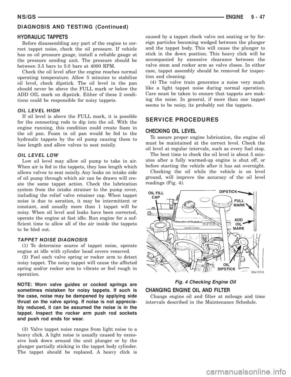
Checking the oil while the vehicle is on level
ground, will improve the accuracy of the oil level
readings (Fig. 4).
CHANGING ENGINE OIL AND FILTER
Change engine oil and filter at mileage and time
intervals described in the Maintenance Schedule.
Fig. 4 Checking Engine Oil
NS/GSENGINE 9 - 47
DIAGNOSIS AND TESTING (Continued)