1996 CHRYSLER VOYAGER length
[x] Cancel search: lengthPage 1772 of 1938

(7) Tighten attaching bolts to 11 to 16 N´m (100 to
140 in. lbs.) torque.
HOOD LATCH STRIKER
REMOVAL
(1) Release hood latch and open hood.
(2) Remove bolts holding striker to inside of hood
(Fig. 44).
(3) Remove hood latch striker from vehicle.
INSTALLATION
(1) Position hood latch striker on vehicle.
(2) Install bolts to hold hood latch striker to hood.
(3) Align hood latch striker to engage smoothly
into hood latch.
(4) Verify hood operation and alignment. Adjust as
necessary.
(5) Tighten attaching bolts to 11 to 16 N´m (100 to
140 in. lbs.) torque.
HOOD RELEASE CABLE
REMOVAL
(1) Remove hood latch.
(2) Disengage cable end from hood latch locking
mechanism.
(3) Slide cable case end sideways in keyhole slot of
hood latch while pinching barb on cable case closed.
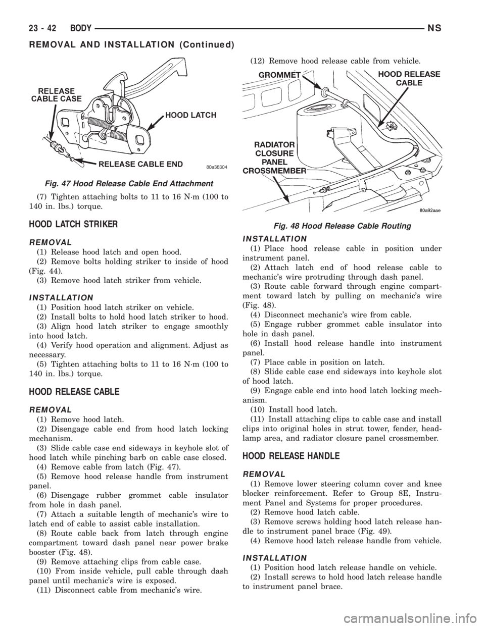
(4) Remove cable from latch (Fig. 47).
(5) Remove hood release handle from instrument
panel.
(6) Disengage rubber grommet cable insulator
from hole in dash panel.
(7) Attach a suitable length of mechanic's wire to
latch end of cable to assist cable installation.
(8) Route cable back from latch through engine
compartment toward dash panel near power brake
booster (Fig. 48).
(9) Remove attaching clips from cable case.
(10) From inside vehicle, pull cable through dash
panel until mechanic's wire is exposed.
(11) Disconnect cable from mechanic's wire.(12) Remove hood release cable from vehicle.
INSTALLATION
(1) Place hood release cable in position under
instrument panel.
(2) Attach latch end of hood release cable to
mechanic's wire protruding through dash panel.
(3) Route cable forward through engine compart-
ment toward latch by pulling on mechanic's wire
(Fig. 48).
(4) Disconnect mechanic's wire from cable.
(5) Engage rubber grommet cable insulator into
hole in dash panel.
(6) Install hood release handle into instrument
panel.
(7) Place cable in position on latch.
(8) Slide cable case end sideways into keyhole slot
of hood latch.
(9) Engage cable end into hood latch locking mech-
anism.
(10) Install hood latch.
(11) Install attaching clips to cable case and install
clips into original holes in strut tower, fender, head-
lamp area, and radiator closure panel crossmember.
HOOD RELEASE HANDLE
REMOVAL
(1) Remove lower steering column cover and knee
blocker reinforcement. Refer to Group 8E, Instru-
ment Panel and Systems for proper procedures.
(2) Remove hood latch cable.
(3) Remove screws holding hood latch release han-
dle to instrument panel brace (Fig. 49).
(4) Remove hood latch release handle from vehicle.
INSTALLATION
(1) Position hood latch release handle on vehicle.
(2) Install screws to hold hood latch release handle
to instrument panel brace.
Fig. 47 Hood Release Cable End Attachment
Fig. 48 Hood Release Cable Routing
23 - 42 BODYNS
REMOVAL AND INSTALLATION (Continued)
Page 1811 of 1938

(b) Mark outline of center hinge on sliding door
to assist in making adjustments.
(c) Loosen center hinge bolts (Fig. 137).
(d) Move hinge fore or aft to position the sliding
door into the correct location.
(e) Tighten center hinge bolts.
(f) Verify alignment. Re-adjust as necessary.
(3) If the sliding door is low at the B-post;
(a) Remove access plug in the sliding door trim
panel.
(b) Open the door to mid-point of travel.
(c) Mark outline of lower roller arm bracket on
sliding door to assist in making adjustments.
(d) Loosen lower roller arm bracket bolts (Fig.
138).
(e) Move hinge downward to raise the door.
(f) Tighten lower roller arm bracket bolts.
(g) Verify alignment. Re-adjust as necessary.
(4) If the sliding door is low at the C-post;
(a) Open the door to mid-point of travel.
(b) Mark outline of center hinge on sliding door
to assist in making adjustments.
(c) Adjust the adjustment bolt up or down to
move the door position. (Fig. 137).
(d) Move hinge downward to raise the door.
(e) Tighten center hinge bolts.
(f) Verify alignment. Re-adjust as necessary.
(5) If the sliding door is high at the B-post;
(a) Remove access plug in the sliding door trim
panel.
(b) Open the door to mid-point of travel.
(c) Mark outline of lower roller arm bracket on
sliding door to assist in making adjustments.
(d) Loosen lower roller arm bracket bolts (Fig.
138).(e) Move hinge upward to raise the door.
(f) Tighten lower roller arm bracket bolts.
(g) Verify alignment. Re-adjust as necessary.
SEAL COMPRESSION
(1) Check seal compression at top and bottom of
B-post seal.
(2) Adjust seal compression at the top of the
B-post seal;
(a) Open door to mid-point of travel.
(b) Mark outline of upper roller arm on bracket
to assist in making adjustments.
(c) Loosen bolts holding upper roller arm to
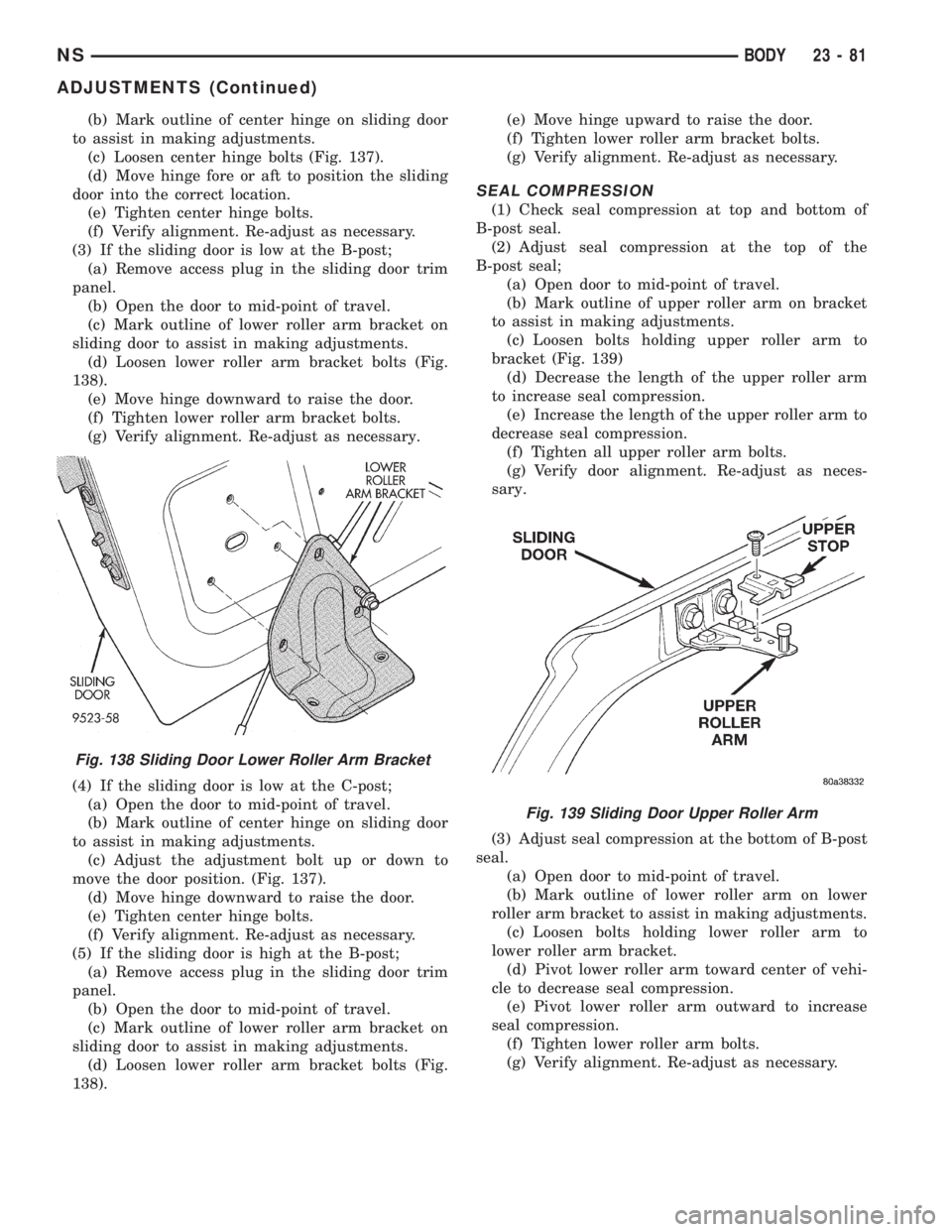
bracket (Fig. 139)
(d) Decrease the length of the upper roller arm
to increase seal compression.
(e) Increase the length of the upper roller arm to
decrease seal compression.
(f) Tighten all upper roller arm bolts.
(g) Verify door alignment. Re-adjust as neces-
sary.
(3) Adjust seal compression at the bottom of B-post
seal.
(a) Open door to mid-point of travel.
(b) Mark outline of lower roller arm on lower
roller arm bracket to assist in making adjustments.
(c) Loosen bolts holding lower roller arm to
lower roller arm bracket.
(d) Pivot lower roller arm toward center of vehi-
cle to decrease seal compression.
(e) Pivot lower roller arm outward to increase
seal compression.
(f) Tighten lower roller arm bolts.
(g) Verify alignment. Re-adjust as necessary.
Fig. 138 Sliding Door Lower Roller Arm Bracket
Fig. 139 Sliding Door Upper Roller Arm
NSBODY 23 - 81
ADJUSTMENTS (Continued)
Page 1914 of 1938

The primary components within the assembly are:
A three port solenoid that activates both of the func-
tions listed above; a pump which contains a switch,
two check valves and a spring/diaphragm, a canister
vent valve (CVV) seal which contains a spring loaded
vent seal valve.
Immediately after a cold start, between predeter-
mined temperature thresholds limits, the three port
solenoid is briefly energized. This initializes the
pump by drawing air into the pump cavity and also
closes the vent seal. During non test conditions the
vent seal is held open by the pump diaphragm
assembly which pushes it open at the full travel posi-
tion. The vent seal will remain closed while the
pump is cycling due to the reed switch triggering of
the three port solenoid that prevents the diaphragm
assembly from reaching full travel. After the brief
initialization period, the solenoid is de-energized
allowing atmospheric pressure to enter the pump
cavity, thus permitting the spring to drive the dia-
phragm which forces air out of the pump cavity and
into the vent system. When the solenoid is energized
and de energized, the cycle is repeated creating flow
in typical diaphragm pump fashion. The pump is con-
trolled in 2 modes:
Pump Mode:The pump is cycled at a fixed rate to
achieve a rapid pressure build in order to shorten the
overall test length.
Test Mode:The solenoid is energized with a fixed
duration pulse. Subsequent fixed pulses occur when
the diaphragm reaches the Switch closure point.
The spring in the pump is set so that the system
will achieve an equalized pressure of about 7.5º H20.
The cycle rate of pump strokes is quite rapid as the
system begins to pump up to this pressure. As the
pressure increases, the cycle rate starts to drop off. If
there is no leak in the system, the pump would even-
tually stop pumping at the equalized pressure. If
there is a leak, it will continue to pump at a rate rep-
resentative of the flow characteristic of the size of the
leak. From this information we can determine if the
leak is larger than the required detection limit (cur-
rently set at .020º orifice by CARB). If a leak is
revealed during the leak test portion of the test, the
test is terminated at the end of the test mode and no
further system checks will be performed.
After passing the leak detection phase of the test,
system pressure is maintained by turning on the
LDP's solenoid until the purge system is activated.
Purge activation in effect creates a leak. The cycle
rate is again interrogated and when it increases due
to the flow through the purge system, the leak check
portion of the diagnostic is complete.
The canister vent valve will unseal the system
after completion of the test sequence as the pumpdiaphragm assembly moves to the full travel position.
Evaporative system functionality will be verified by
using the stricter evap purge flow monitor. At an
appropriate warm idle the LDP will be energized to
seal the canister vent. The purge flow will be clocked
up from some small value in an attempt to see a
shift in the 02 control system. If fuel vapor, indicated
by a shift in the 02 control, is present the test is
passed. If not, it is assumed that the purge system is
not functioning in some respect. The LDP is again
turned off and the test is ended.
TRIP DEFINITION
A ªTripº means vehicle operation (following an
engine-off period) of duration and driving mode such
that all components and systems are monitored at
least once by the diagnostic system. The monitors
must successfully pass before the PCM can verify
that a previously malfunctioning component is meet-
ing the normal operating conditions of that compo-
nent. For misfire or fuel system malfunction, the
MIL may be extinguished if the fault does not recur
when monitored during three subsequent sequential
driving cycles in which conditions are similar to
those under which the malfunction was first deter-
mined.
Anytime the MIL is illuminated, a DTC is stored.
The DTC can self erase only when the MIL has been
extinguished. Once the MIL is extinguished, the
PCM must pass the diagnostic test for the most
recent DTC for 40 warm-up cycles (80 warm-up
cycles for the Fuel System Monitor and the Misfire
Monitor). A warm-up cycle can best be described by
the following:
²The engine must be running
²A rise of 40ÉF in engine temperature must occur
from the time when the engine was started
²Engine coolant temperature must reach at least
160ÉF
²A ªdriving cycleº that consists of engine start up
and engine shut off.
Once the above conditions occur, the PCM is con-
sidered to have passed a warm-up cycle. Due to the
conditions required to extinguish the MIL and erase
the DTC, it is most important that after a repair has
been made, all DTC's be erased and the repair veri-
fied.
COMPONENT MONITORS
There are several components that will affect vehi-
cle emissions if they malfunction. If one of these com-
ponents malfunctions the Malfunction Indicator
Lamp (Check Engine) will illuminate.
Some of the component monitors are checking for
proper operation of the part. Electrically operated
25 - 10 EMISSION CONTROL SYSTEMSNS
DESCRIPTION AND OPERATION (Continued)