Page 1669 of 1938
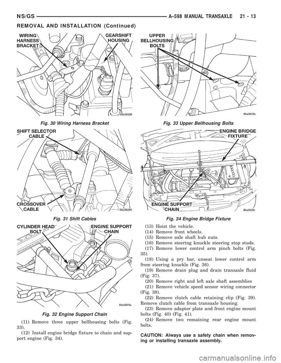
(11) Remove three upper bellhousing bolts (Fig.
33).
(12) Install engine bridge fixture to chain and sup-
port engine (Fig. 34).(13) Hoist the vehicle.
(14) Remove front wheels.
(15) Remove axle shaft hub nuts.
(16) Remove steering knuckle steering stop studs.
(17) Remove lower control arm pinch bolts (Fig.
35).
(18) Using a pry bar, unseat lower control arm
from steering knuckle (Fig. 36).
(19) Remove drain plug and drain transaxle fluid
(Fig. 37).
(20) Remove right and left axle shaft assemblies
(21) Remove vehicle speed sensor wiring connector
(Fig. 38).
(22) Remove clutch cable retaining clip (Fig. 39).
Remove clutch cable from transaxle housing.
(23) Remove adapter plate and front engine mount
bolts (Fig. 40) (Fig. 41).
(24) Remove two remaining rear engine mount
bolts.
CAUTION: Always use a safety chain when remov-
ing or installing transaxle assembly.
Fig. 30 Wiring Harness Bracket
Fig. 31 Shift Cables
Fig. 32 Engine Support Chain
Fig. 33 Upper Bellhousing Bolts
Fig. 34 Engine Bridge Fixture
NS/GSA±598 MANUAL TRANSAXLE 21 - 13
REMOVAL AND INSTALLATION (Continued)
Page 1670 of 1938
(25) Install transmission jack under transaxle
assembly.
(26) Remove left fender splash shield.
(27) Remove (4) left mount bolts (Fig. 42).(28) Remove lower bellhousing bolts.
(29) Lower transaxle and remove.
INSTALLATION
(1) For installation, reverse removal procedure.
NOTE: Lower control arm pinch bolts must be
installed with the bolt heads to the rear of the ball
joints.
(2) Fill transaxle to the proper level with the spec-
ified lubricant.
(3) While the vehicle is elevated slightly, run the
transaxle through all the forward gears. Apply
brakes and shift into reverse. Run the transaxle
through reverse gear.
Fig. 35 Lower Control Arm Pinch Bolt
Fig. 36 Unseat Control Arm
Fig. 37 Transaxle Drain Plug
Fig. 38 Vehicle Speed Sensor
Fig. 39 Clutch Cable Clip
21 - 14 A±598 MANUAL TRANSAXLENS/GS
REMOVAL AND INSTALLATION (Continued)
Page 1674 of 1938
(12) Remove the front wheels.(13) Remove the two (2) axle shaft hub nuts.
(14) Remove three upper bellhousing bolts.
(15) Remove steering stop studs at steering knuck-
les.
(16) Remove lower control arm pinch bolts (Fig.
56).
(17) Using a pry bar, unseat lower control arm
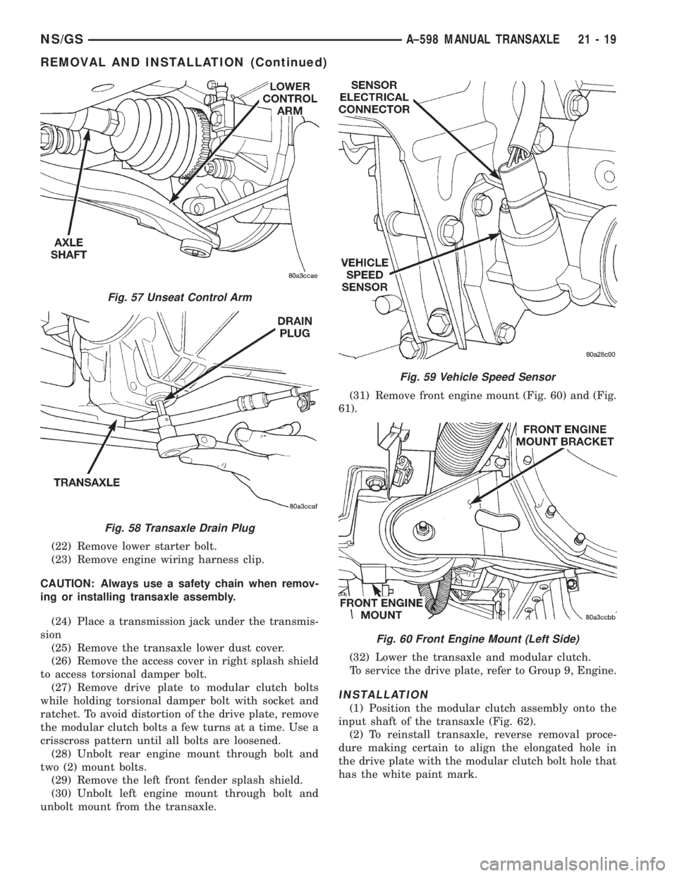
from steering knuckle (Fig. 57).
(18) Remove drain plug and drain transaxle fluid
(Fig. 58).
(19) Remove right and left axle shaft assemblies
(20) Remove vehicle speed sensor wiring connector
(Fig. 59).
(21) Remove structural brace from engine and
transaxle.
Fig. 52 Engine Support Chain Ð Typical
Fig. 53 Throttle Control Shield
Fig. 54 Throttle Control Support Bracket
Fig. 55 Shift Cables
Fig. 56 Lower Control Arm Pinch Bolt
21 - 18 A±598 MANUAL TRANSAXLENS/GS
REMOVAL AND INSTALLATION (Continued)
Page 1675 of 1938
(22) Remove lower starter bolt.
(23) Remove engine wiring harness clip.
CAUTION: Always use a safety chain when remov-
ing or installing transaxle assembly.
(24) Place a transmission jack under the transmis-
sion
(25) Remove the transaxle lower dust cover.
(26) Remove the access cover in right splash shield
to access torsional damper bolt.
(27) Remove drive plate to modular clutch bolts
while holding torsional damper bolt with socket and
ratchet. To avoid distortion of the drive plate, remove
the modular clutch bolts a few turns at a time. Use a
crisscross pattern until all bolts are loosened.
(28) Unbolt rear engine mount through bolt and
two (2) mount bolts.
(29) Remove the left front fender splash shield.
(30) Unbolt left engine mount through bolt and
unbolt mount from the transaxle.(31) Remove front engine mount (Fig. 60) and (Fig.
61).
(32) Lower the transaxle and modular clutch.
To service the drive plate, refer to Group 9, Engine.
INSTALLATION
(1) Position the modular clutch assembly onto the
input shaft of the transaxle (Fig. 62).
(2) To reinstall transaxle, reverse removal proce-
dure making certain to align the elongated hole in
the drive plate with the modular clutch bolt hole that
has the white paint mark.
Fig. 57 Unseat Control Arm
Fig. 58 Transaxle Drain Plug
Fig. 59 Vehicle Speed Sensor
Fig. 60 Front Engine Mount (Left Side)
NS/GSA±598 MANUAL TRANSAXLE 21 - 19
REMOVAL AND INSTALLATION (Continued)
Page 1715 of 1938
(14) Apply a bead of MopartGasket Maker or
equivalent onto bearing support plate. Install bearing
support plate.
(15) Install necessary shim calculated from Step
12
(16) Install bearing retainer plate. Tighten bearing
retainer plate to 17 N´m (250 in. lbs.).
(17) Install 5th drive gear onto the input shaft.
(18) Install 5th gear, synchro, fork, and plate.
(19) Install 5th gear synchro snap ring.
(20) Install 5th gear shift fork roll pin.
(21) Use Special Tool 6252 to hold 5th gear and
install new 5th gear nut at input shaft. Tighten the
retaining nut to 176 N´m (130 ft. lbs.).
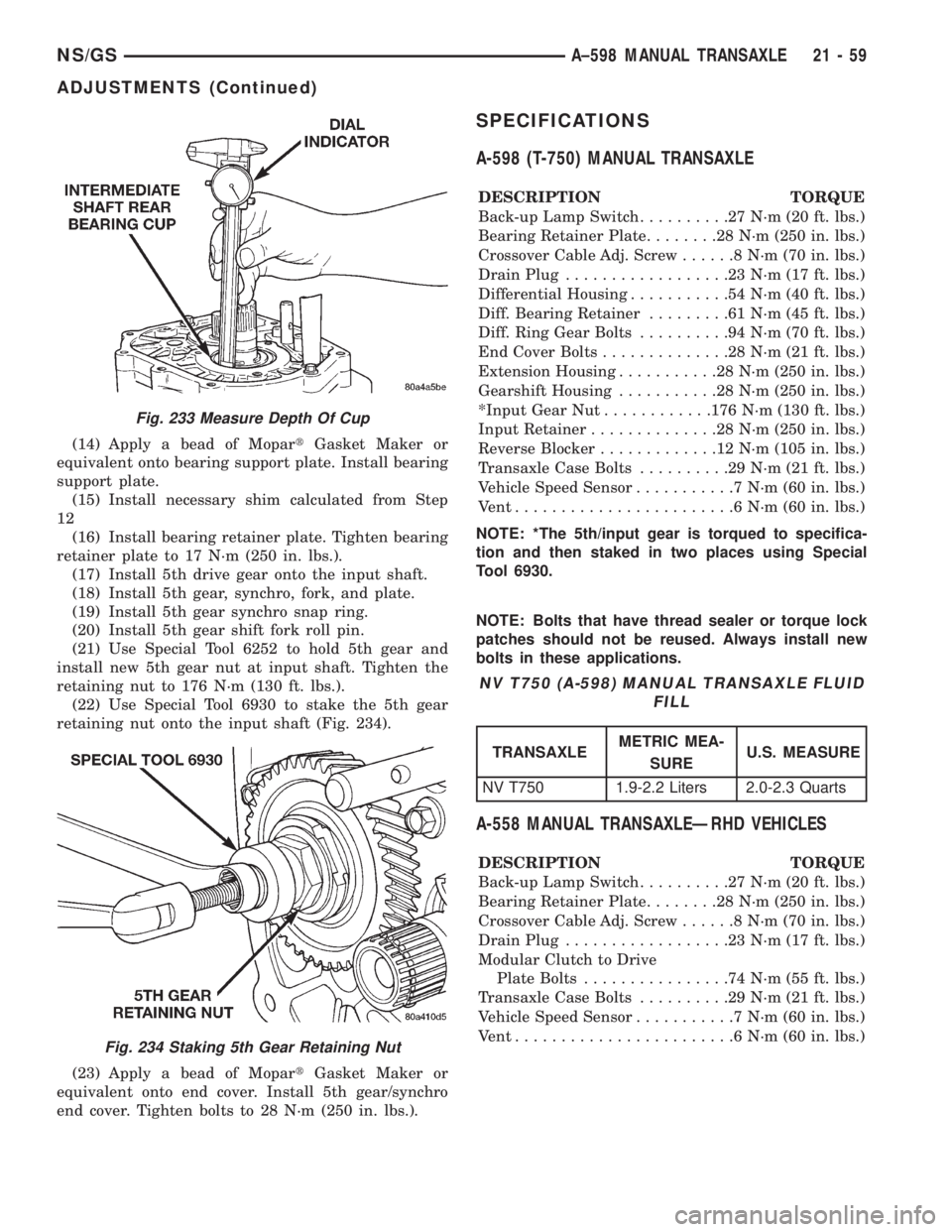
(22) Use Special Tool 6930 to stake the 5th gear
retaining nut onto the input shaft (Fig. 234).
(23) Apply a bead of MopartGasket Maker or
equivalent onto end cover. Install 5th gear/synchro
end cover. Tighten bolts to 28 N´m (250 in. lbs.).
SPECIFICATIONS
A-598 (T-750) MANUAL TRANSAXLE
DESCRIPTION TORQUE
Back-up Lamp Switch..........27N´m(20ft.lbs.)
Bearing Retainer Plate........28N´m(250 in. lbs.)
Crossover Cable Adj. Screw......8N´m(70in.lbs.)
Drain Plug..................23N´m(17ft.lbs.)
Differential Housing...........54N´m(40ft.lbs.)
Diff. Bearing Retainer.........61N´m(45ft.lbs.)
Diff. Ring Gear Bolts..........94N´m(70ft.lbs.)
End Cover Bolts..............28N´m(21ft.lbs.)
Extension Housing...........28N´m(250 in. lbs.)
Gearshift Housing...........28N´m(250 in. lbs.)
*Input Gear Nut............176 N´m (130 ft. lbs.)
Input Retainer..............28N´m(250 in. lbs.)
Reverse Blocker.............12N´m(105 in. lbs.)
Transaxle Case Bolts..........29N´m(21ft.lbs.)
Vehicle Speed Sensor...........7N´m(60in.lbs.)
Vent........................6N´m(60in.lbs.)
NOTE: *The 5th/input gear is torqued to specifica-
tion and then staked in two places using Special
Tool 6930.
NOTE: Bolts that have thread sealer or torque lock
patches should not be reused. Always install new
bolts in these applications.
A-558 MANUAL TRANSAXLEÐRHD VEHICLES
DESCRIPTION TORQUE
Back-up Lamp Switch..........27N´m(20ft.lbs.)
Bearing Retainer Plate........28N´m(250 in. lbs.)
Crossover Cable Adj. Screw......8N´m(70in.lbs.)
Drain Plug..................23N´m(17ft.lbs.)
Modular Clutch to Drive
Plate Bolts................74N´m(55ft.lbs.)
Transaxle Case Bolts..........29N´m(21ft.lbs.)
Vehicle Speed Sensor...........7N´m(60in.lbs.)
Vent........................6N´m(60in.lbs.)
Fig. 233 Measure Depth Of Cup
Fig. 234 Staking 5th Gear Retaining Nut
NV T750 (A-598) MANUAL TRANSAXLE FLUID
FILL
TRANSAXLEMETRIC MEA-
SUREU.S. MEASURE
NV T750 1.9-2.2 Liters 2.0-2.3 Quarts
NS/GSA±598 MANUAL TRANSAXLE 21 - 59
ADJUSTMENTS (Continued)
Page 1839 of 1938
COMPRESSOR
REMOVAL
WARNING: REFER TO REFRIGERANT SERVICE
PROCEDURES FOR INFORMATION REGARDING
PROPER RECOVERY OF THE REFRIGERANT
BEFORE ATTEMPTING TO REMOVE THE COM-
PRESSOR.
(1) Disconnect negative battery cable.
(2) Pinch off coolant lines to rear Heat unit (if
equipped). Drain engine coolant.
(3) Remove upper radiator hose.
(4) Remove drive belt (refer to Group 7, Cooling
System). Disconnect compressor clutch wire lead.
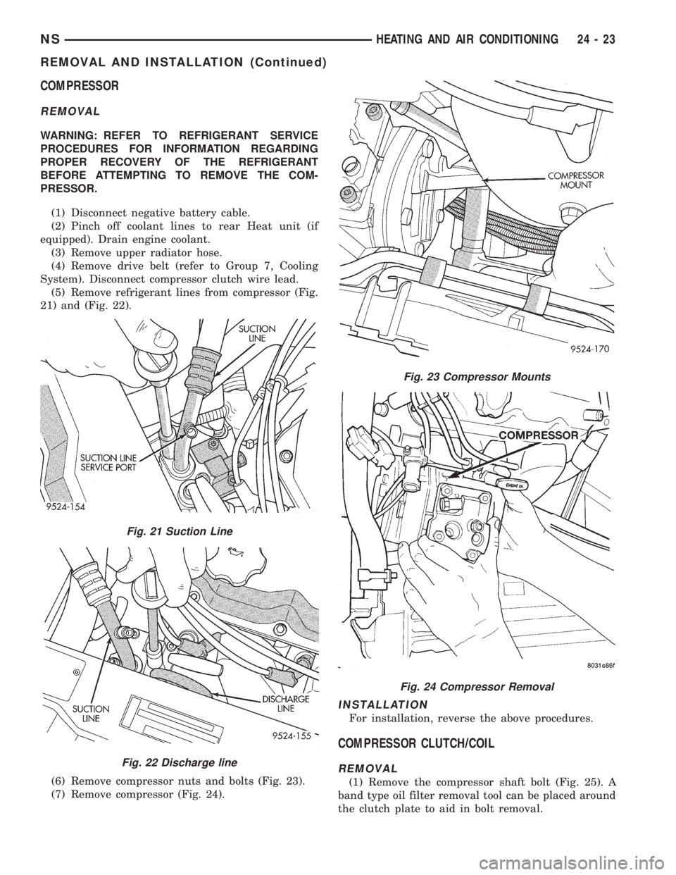
(5) Remove refrigerant lines from compressor (Fig.
21) and (Fig. 22).
(6) Remove compressor nuts and bolts (Fig. 23).
(7) Remove compressor (Fig. 24).
INSTALLATION
For installation, reverse the above procedures.
COMPRESSOR CLUTCH/COIL
REMOVAL
(1) Remove the compressor shaft bolt (Fig. 25). A
band type oil filter removal tool can be placed around
the clutch plate to aid in bolt removal.
Fig. 21 Suction Line
Fig. 22 Discharge line
Fig. 23 Compressor Mounts
Fig. 24 Compressor Removal
NSHEATING AND AIR CONDITIONING 24 - 23
REMOVAL AND INSTALLATION (Continued)
Page 1845 of 1938
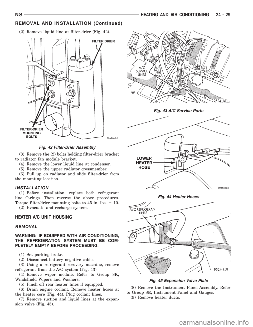
(2) Remove liquid line at filter-drier (Fig. 42).
(3) Remove the (2) bolts holding filter-drier bracket
to radiator fan module bracket.
(4) Remove the lower liquid line at condenser.
(5) Remove the upper radiator crossmember.
(6) Pull up on radiator and slide filter-drier from
the mounting location.
INSTALLATION
(1) Before installation, replace both refrigerant
line O-rings. Then reverse the above procedures.
Torque filter/drier mounting bolts to 45 in. lbs.610.
(2) Evacuate and recharge system.
HEATER A/C UNIT HOUSING
REMOVAL
WARNING: IF EQUIPPED WITH AIR CONDITIONING,
THE REFRIGERATION SYSTEM MUST BE COM-
PLETELY EMPTY BEFORE PROCEEDING.
(1) Set parking brake.
(2) Disconnect battery negative cable.
(3) Using a refrigerant recovery machine, remove
refrigerant from the A/C system (Fig. 43).
(4) Remove wiper module. Refer to Group 8K,
Windshield Wipers and Washers.
(5) Pinch off rear heater lines if equipped.
(6) Drain engine coolant. Remove heater hoses at
the heater core (Fig. 44). Plug coolant lines.
(7) Remove suction and liquid lines at the expan-
sion valve (Fig. 45).(8) Remove the Instrument Panel Assembly. Refer
to Group 8E, Instrument Panel and Gauges.
(9) Remove heater ducts.
Fig. 42 Filter-Drier Assembly
Fig. 43 A/C Service Ports
Fig. 44 Heater Hoses
Fig. 45 Expansion Valve Plate
NSHEATING AND AIR CONDITIONING 24 - 29
REMOVAL AND INSTALLATION (Continued)
Page 1846 of 1938
(10) Disconnect the two upper mounts from the
upper reinforcement and the lower mount from the
tunnel.
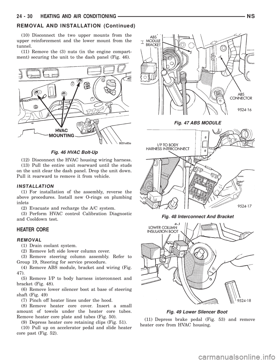
(11) Remove the (3) nuts (in the engine compart-
ment) securing the unit to the dash panel (Fig. 46).
(12) Disconnect the HVAC housing wiring harness.
(13) Pull the entire unit rearward until the studs
on the unit clear the dash panel. Drop the unit down.
Pull it rearward to remove it from vehicle.
INSTALLATION
(1) For installation of the assembly, reverse the
above procedures. Install new O-rings on plumbing
inlets
(2) Evacuate and recharge the A/C system.
(3) Perform HVAC control Calibration Diagnostic
and Cooldown test.
HEATER CORE
REMOVAL
(1) Drain coolant system.
(2) Remove left side lower column cover.
(3) Remove steering column assembly. Refer to
Group 19, Steering for service procedure.
(4) Remove ABS module, bracket and wiring (Fig.
47).
(5) Remove I/P to body harness interconnect and
bracket (Fig. 48).
(6) Remove lower silencer boot at base of steering
shaft (Fig. 49)
(7) Pinch off heater lines under the hood.
(8) Remove heater core cover. Insert a small
amount of towels under the heater core tubes.
Remove heater core plate and tubes (Fig. 50).
(9) Depress heater core retaining clips (Fig. 51).
(10) Pull up on accelerator pedal and slide heater
core past (Fig. 52).(11) Depress brake pedal (Fig. 53) and remove
heater core from HVAC housing.
Fig. 46 HVAC Bolt-Up
Fig. 47 ABS MODULE
Fig. 48 Interconnect And Bracket
Fig. 49 Lower Silencer Boot
24 - 30 HEATING AND AIR CONDITIONINGNS
REMOVAL AND INSTALLATION (Continued)