1996 CHRYSLER VOYAGER drain bolt
[x] Cancel search: drain boltPage 1861 of 1938

CAUTION: Do not damage the evaporator insulation
liner during installation.
(3) Carefully install the evaporator and expansion
valve straight into the unit. Do not scratch the seal-
ing surfaces with the plumbing extension tube pilots.
(4) Determine the amount of old refrigerant oil
drained from the evaporator. Add this amount (of
clean refrigerant oil) back into the system.
(5) Carefully align the expansion valve onto the
pilot tubes of the plumbing extension (do not scratch
the sealing surface). Install the bolt through the
plumbing plate into the unit sealing plate. Tighten
bolts to 2363 N´m (200630 inch pounds) torque.
(6) Install evaporator cover and blower scroll.
(7) Install quarter trim panel, evacuate/charge sys-
tem, and perform the performance test.
REAR AIR CONDITIONING LINES
WARNING: THE REFRIGERATION SYSTEM MUST
BE COMPLETELY EMPTY BEFORE PROCEEDING
WITH THIS OPERATION.
REMOVAL
(1) Hoist vehicle
(2) Remove compression fittings to the suction and
liquid lines located on the right, outboard side of the
underbody, rearward of the front crossmember. (Fig.
2)
(3) remove (1) bolt securing a/c lines to block
located on the right, outboard side of the underbody,
rearward of the rear wheel and tire. (Fig. 5)
(4) Remove (3) straps securing underbody lines.
(Fig. 1)
(5) Separate and remove a/c lines from vehicle.
INSTALLATION
(1) Before installation, replace all O-rings and gas-
kets. Coat all sealing surfaces with approved wax-
free refrigerant oil. Then, reverse the above
procedures.
(2) Evacuate and recharge system.
REAR HEATER A/C AIR OUTLETS
REMOVAL
Separate barrel from bezel by pulling outward.
INSTALLATION
For installation, push the outlet firmly into the
opening until it locks into place.
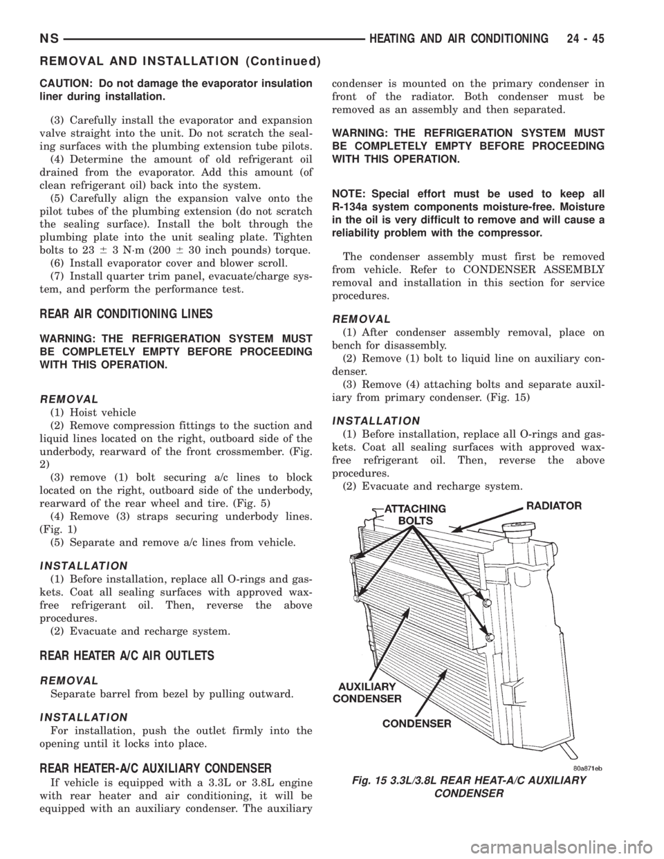
REAR HEATER-A/C AUXILIARY CONDENSER
If vehicle is equipped with a 3.3L or 3.8L engine
with rear heater and air conditioning, it will be
equipped with an auxiliary condenser. The auxiliarycondenser is mounted on the primary condenser in
front of the radiator. Both condenser must be
removed as an assembly and then separated.
WARNING: THE REFRIGERATION SYSTEM MUST
BE COMPLETELY EMPTY BEFORE PROCEEDING
WITH THIS OPERATION.
NOTE: Special effort must be used to keep all
R-134a system components moisture-free. Moisture
in the oil is very difficult to remove and will cause a
reliability problem with the compressor.
The condenser assembly must first be removed
from vehicle. Refer to CONDENSER ASSEMBLY
removal and installation in this section for service
procedures.
REMOVAL
(1) After condenser assembly removal, place on
bench for disassembly.
(2) Remove (1) bolt to liquid line on auxiliary con-
denser.
(3) Remove (4) attaching bolts and separate auxil-
iary from primary condenser. (Fig. 15)
INSTALLATION
(1) Before installation, replace all O-rings and gas-
kets. Coat all sealing surfaces with approved wax-
free refrigerant oil. Then, reverse the above
procedures.
(2) Evacuate and recharge system.
Fig. 15 3.3L/3.8L REAR HEAT-A/C AUXILIARY
CONDENSER
NSHEATING AND AIR CONDITIONING 24 - 45
REMOVAL AND INSTALLATION (Continued)
Page 1871 of 1938

capacity of the system and consequently result in
higher discharge air temperatures.
NOTE: The oil used in the Denso 2.5L Turbo Diesel
and the Denso 2.0L gasoline engine compressors is
ND-8 PAG R134a refrigerant oil. Only refrigerant oil
of the same type should be used to service the sys-
tem. Do not use any other oil. The oil container
should be kept tightly capped until it is ready for
use. Tightly cap afterwards to prevent contamina-
tion from dirt and moisture. Refrigerant oil will
quickly absorb any moisture it comes in contact
with. Special effort must be used to keep all R-134a
system components moisture-free. Moisture in the
oil is very difficult to remove and will cause a reli-
ability problem with the compressor.
It will not be necessary to check oil level in the
compressor or to add oil unless there has been an oil
loss. Oil loss at a leak point will be evident by the
presence of a wet, shiny surface around the leak.
REFRIGERANT OIL LEVEL CHECK
When an air conditioning system is first assem-
bled, all components (except the compressor) are
refrigerant oil free. After the system has been
charged with R134a refrigerant and operated, the oil
in the compressor is dispersed through the lines and
components. The evaporator, condenser, and filter-
drier will retain a significant amount of oil, refer to
the Refrigerant Oil Capacities chart. When a compo-
nent is replaced, the specified amount of refrigerant
oil must be added. When the compressor is replaced,
the amount of oil that is retained in the rest of the
system must be drained from the replacement com-
pressor. When a line or component has ruptured and
oil has escaped, the compressor should be removed
and drained. The compressor is drained through the
suction port or by removing the sump bolt on top of
the compressor, refer to Compressor Removal and
Installation procedures. The filter-drier must be
replaced along with the ruptured part. The oil capac-
ity of the system, minus the amount of oil still in the
remaining components, can be measured and poured
into the suction port of the compressor.
Example: The evaporator retains 50 ml (1.7 oz.).
The condenser retains 30 ml (1 oz) of oil, and system
capacity may be 220 ml (7.40 oz) of oil.
220 ml minus 90 ml = 130 ml (4.40 oz.).
CAUTION: The refrigerant oil used in a R-134a A/C
system is unique. Use only oils which were designed
to work with R-134a refrigerant. The oil designated
for the Denso 2.5L Turbo Diesel and Denso 2.0L gas-
oline engine compressors is ND-8 PAG compressor
oil. For gasoline vehicles still using R-12 refrigerant,
use ND8 PAG compressor oil.
SERVICING REFRIGERANT OIL LEVEL
(1) Using a refrigerant recovery machine, remove
refrigerant from the A/C system.
(2) Remove refrigerant lines from A/C compressor.
(3) Remove compressor from vehicle.
(4) From suction port on top of compressor, drain
refrigerant oil from compressor.
(5) Add system capacity minus the capacity of
components that have not been replaced through suc-
tion port on compressor. Refer to the Refrigerant Oil
Capacity Chart.
(6) Install compressor, connect refrigerant lines,
evacuate, and charge refrigerant system.
DIAGNOSIS AND TESTING
ACTUATOR CALIBRATION/DIAGNOSTICS AND
COOLDOWN TEST
GENERAL INFORMATION
If the HVAC control module is replaced, the Cali-
bration Diagnostic and Cooldown tests will need to
be performed. Once this group of tests have success-
fully passed, they can be performed individually. The
engine must be running during the test to provide
hot coolant for the heater, A/C compressor operation
and to assure that the actuators are calibrated cor-
rectly. The HVAC control module is capable of trou-
bleshooting the system in approximately 120 seconds.
If a condition is detected, an error code is displayed.
The error code cannot be erased until the condition is
repaired and the diagnostic test is performed. Check
wire before replacing components, refer to Group 8W,
Wiring Diagrams.
CAUTION: Do not remove the actuators from the
Heater-A/C unit assembly with power applied.
Removal should only be done with the Ignition OFF.
The actuators have no mechanical stops to limit the
travel. If the actuator rotates and is not connected to
the unit assembly, it will become out of calibration.
ACTUATOR CALIBRATION
Mode, Blend and Zone (if equipped) door calibra-
tion compensates for mechanical variations in the
REFRIGERANT OIL CAPACITIES
REFRIGERANT OIL CAPACITIES
COMPONENT ML OZ
Compressor 135 ml 4.5 oz
Filter-Drier 30 ml 1.0 oz
Condenser 30 ml 1.0 oz
Evaporator 50 ml 1.7 oz
NS/GSHEATING AND AIR CONDITIONING 24 - 5
DESCRIPTION AND OPERATION (Continued)
Page 1892 of 1938

(2) Hand-start the stud into the expansion valve
and torque to7-11N´m(64-96in.lbs.).
(3) Carefully install the expansion valve to the
sealing plate. Install the two screws and tighten 8 to
14 N´m (70 to 130 in. lbs.) torque.
(4) Carefully install the refrigerant lines and seal-
ing plate to the expansion valve. Install the nut and
tighten 20 to 26 N´m (170 to 230 in. lbs.) torque.
(5) Install the ground wire at dash panel.
(6) Pull generator back into the proper position for
bracket mounting.
(7) Install generator field wire connector.
(8) Install the upper generator bracket.
(9) Install accessory drive belt.
(10) Evacuate and recharge system.
(11) After expansion valve is installed, the system
is charged, and leaks have checked repeat the A/C
performance check.
FILTER-DRIER ASSEMBLY
REMOVAL
WARNING: THE REFRIGERATION SYSTEM MUST
BE COMPLETELY EMPTY BEFORE PROCEEDING
WITH THIS OPERATION.
(1) Recover A/C system refrigerant.
(2) Remove liquid line at filter-drier (Fig. 21).
(3) Remove the (2) bolts holding filter-drier bracket
to radiator fan module bracket.
(4) Remove the lower liquid line at condenser.
(5) Remove the upper radiator crossmember.
(6) Pull up on radiator and slide filter-drier from
the mounting location.
INSTALLATION
(1) Before installation, replace both refrigerant
line O-rings. Then reverse the above procedures.
(2) Evacuate and recharge system.
HEATER A/C UNIT HOUSING
REMOVAL
WARNING: IF EQUIPPED WITH AIR CONDITIONING,
THE REFRIGERATION SYSTEM MUST BE COM-
PLETELY EMPTY BEFORE PROCEEDING.
(1) Set parking brake.
(2) Disconnect battery negative cable.
(3) Using a refrigerant recovery machine, remove
refrigerant from the A/C system.
(4) Remove wiper module. Refer to Group 8K,
Windshield Wipers and Washers.
(5) Drain engine coolant. Remove heater hoses at
the heater core, refer to Heater Hoses Removal and
Installation procedures. Plug coolant lines.(6) Remove suction and liquid lines at the expan-
sion valve (Fig. 27).
(7) Remove the Instrument Panel Assembly. Refer
to Group 8E, Instrument Panel and Systems.
(8) Remove heater ducts.
(9) Disconnect the two upper mounts from the
upper reinforcement and the lower mount from the
tunnel.
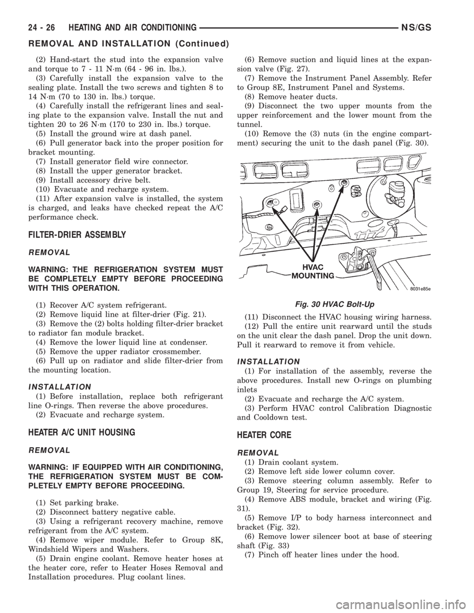
(10) Remove the (3) nuts (in the engine compart-
ment) securing the unit to the dash panel (Fig. 30).
(11) Disconnect the HVAC housing wiring harness.
(12) Pull the entire unit rearward until the studs
on the unit clear the dash panel. Drop the unit down.
Pull it rearward to remove it from vehicle.
INSTALLATION
(1) For installation of the assembly, reverse the
above procedures. Install new O-rings on plumbing
inlets
(2) Evacuate and recharge the A/C system.
(3) Perform HVAC control Calibration Diagnostic
and Cooldown test.
HEATER CORE
REMOVAL
(1) Drain coolant system.
(2) Remove left side lower column cover.
(3) Remove steering column assembly. Refer to
Group 19, Steering for service procedure.
(4) Remove ABS module, bracket and wiring (Fig.
31).
(5) Remove I/P to body harness interconnect and
bracket (Fig. 32).
(6) Remove lower silencer boot at base of steering
shaft (Fig. 33)
(7) Pinch off heater lines under the hood.
Fig. 30 HVAC Bolt-Up
24 - 26 HEATING AND AIR CONDITIONINGNS/GS
REMOVAL AND INSTALLATION (Continued)