1996 CHRYSLER VOYAGER drain bolt
[x] Cancel search: drain boltPage 1307 of 1938
WARNING: RELEASE FUEL SYSTEM PRESSURE
BEFORE DISCONNECTING QUICK-CONNECT FIT-
TINGS AT FUEL FILTER. REFER TO THE FUEL
PRESSURE RELEASE PROCEDURE.
REMOVAL
(1) Perform fuel system pressure release.
(2) Disconnect quick-connect fittings from fuel
pump module and chassis fuel supply tube. Refer to
Quick-Connect Fittings in this section.
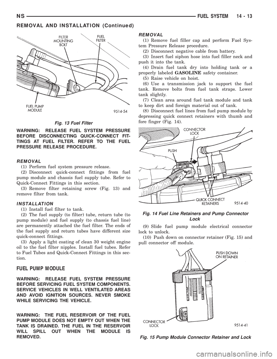
(3) Remove filter retaining screw (Fig. 13) and
remove filter from tank.
INSTALLATION
(1) Install fuel filter to tank.
(2) The fuel supply (to filter) tube, return tube (to
pump module) and fuel supply (to chassis fuel line)
are permanently attached the fuel filter. The ends of
the fuel supply and return tubes have different size
quick-connect fittings.
(3) Apply a light coating of clean 30 weight engine
oil to the fuel filter nipples. Install fuel tubes. Refer
to Fuel Tubes and Quick-Connect Fittings in this sec-
tion.
FUEL PUMP MODULE
WARNING: RELEASE FUEL SYSTEM PRESSURE
BEFORE SERVICING FUEL SYSTEM COMPONENTS.
SERVICE VEHICLES IN WELL VENTILATED AREAS
AND AVOID IGNITION SOURCES. NEVER SMOKE
WHILE SERVICING THE VEHICLE.
WARNING: THE FUEL RESERVOIR OF THE FUEL
PUMP MODULE DOES NOT EMPTY OUT WHEN THE
TANK IS DRAINED. THE FUEL IN THE RESERVOIR
WILL SPILL OUT WHEN THE MODULE IS
REMOVED.
REMOVAL
(1) Remove fuel filler cap and perform Fuel Sys-
tem Pressure Release procedure.
(2) Disconnect negative cable from battery.
(3) Insert fuel siphon hose into fuel filler neck and
push it into the tank.
(4) Drain fuel tank dry into holding tank or a
properly labeledGASOLINEsafety container.
(5) Raise vehicle on hoist.
(6) Use a transmission jack to support the fuel
tank. Remove bolts from fuel tank straps. Lower
tank slightly.
(7) Clean area around fuel tank module and tank
to keep dirt and foreign material out of tank.
(8) Disconnect fuel lines from fuel pump module by
depressing quick connect retainers with thumb and
fore finger (Fig. 14).
(9) Slide fuel pump module electrical connector
lock to unlock.
(10) Push down on connector retainer (Fig. 15) and
pull connector off module.
Fig. 13 Fuel Filter
Fig. 14 Fuel Line Retainers and Pump Connector
Lock
Fig. 15 Pump Module Connector Retainer and Lock
NSFUEL SYSTEM 14 - 13
REMOVAL AND INSTALLATION (Continued)
Page 1311 of 1938
(7) Install fuel pump module. Refer to Fuel Pump
Module in this section.
FUEL TANK
WARNING: RELEASE FUEL SYSTEM PRESSURE
BEFORE SERVICING FUEL SYSTEM COMPONENTS.
SERVICE VEHICLES IN WELL VENTILATED AREAS
AND AVOID IGNITION SOURCES. NEVER SMOKE
WHILE SERVICING THE VEHICLE.
REMOVAL
(1) Disconnect negative cable from battery.
(2) Remove fuel filler cap and perform Fuel Sys-
tem Pressure Release procedure.
(3) Insert fuel siphon hose into fuel filler neck and
push it into the tank.
(4) Drain fuel tank dry into holding tank or a
properly labeledGASOLINEsafety container.
(5) Raise vehicle on hoist.
(6) Disconnect both the fuel fill and fuel vent rub-
ber hoses at the fuel tank.(7) Disconnect fuel supply lines from the steel sup-
ply line.
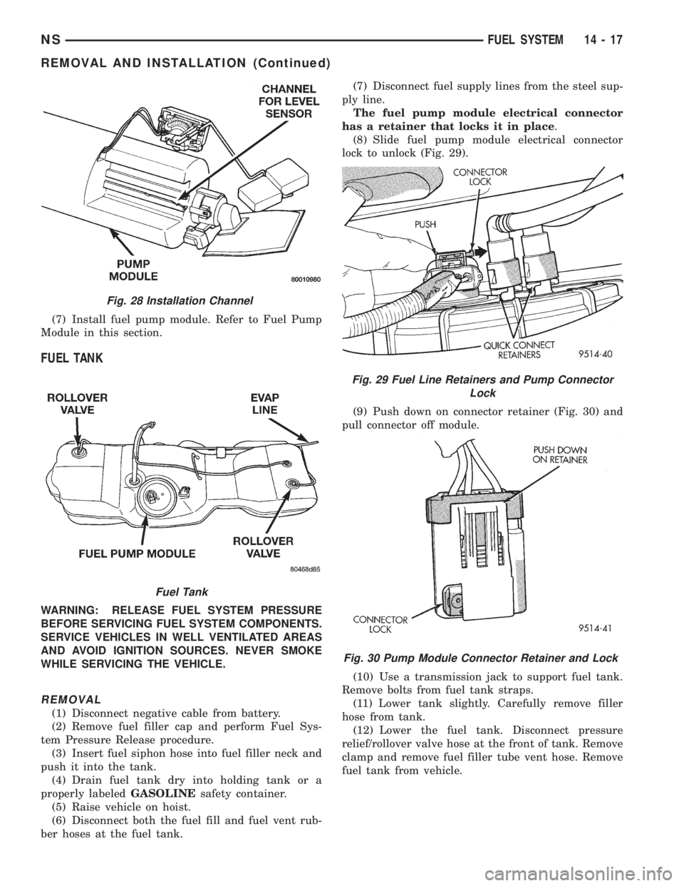
The fuel pump module electrical connector
has a retainer that locks it in place.
(8) Slide fuel pump module electrical connector
lock to unlock (Fig. 29).
(9) Push down on connector retainer (Fig. 30) and
pull connector off module.
(10) Use a transmission jack to support fuel tank.
Remove bolts from fuel tank straps.
(11) Lower tank slightly. Carefully remove filler
hose from tank.
(12) Lower the fuel tank. Disconnect pressure
relief/rollover valve hose at the front of tank. Remove
clamp and remove fuel filler tube vent hose. Remove
fuel tank from vehicle.
Fig. 28 Installation Channel
Fuel Tank
Fig. 29 Fuel Line Retainers and Pump Connector
Lock
Fig. 30 Pump Module Connector Retainer and Lock
NSFUEL SYSTEM 14 - 17
REMOVAL AND INSTALLATION (Continued)
Page 1393 of 1938
fuel fitting. Refer to Tube/Fitting Assembly in the
Fuel Delivery section of this Group.
(7) Attach filler line to filler tube. Pull on connec-
tor to make sure of connection.
(8) Fill fuel tank, replace cap, and connect battery
negative cable.
FUEL RESERVOIR MODULE
REMOVAL
WARNING: THE FUEL RESERVOIR OF THE FUEL
MODULE DOES NOT EMPTY OUT WHEN THE TANK
IS DRAINED. THE FUEL IN THE RESERVOIR WILL
SPILL OUT WHEN THE MODULE IS REMOVED.
(1) Disconnect negative cable from battery.
(2) Insert fuel siphon hose into fuel filler neck and
push it into the tank.
(3) Drain fuel tank dry into holding tank or a
properly labeleddieselsafety container.
(4) Raise vehicle on hoist.
(5) Use a transmission jack to support the fuel
tank. Remove bolts from fuel tank straps. Lower
tank slightly.
(6) Clean area around fuel reservoir module and
tank to keep dirt and foreign material out of tank.
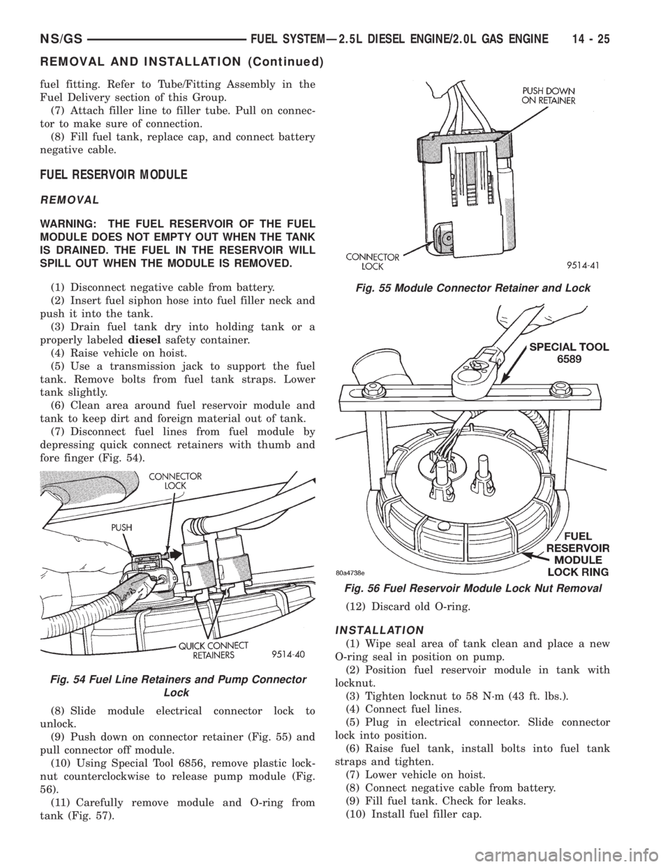
(7) Disconnect fuel lines from fuel module by
depressing quick connect retainers with thumb and
fore finger (Fig. 54).
(8) Slide module electrical connector lock to
unlock.
(9) Push down on connector retainer (Fig. 55) and
pull connector off module.
(10) Using Special Tool 6856, remove plastic lock-
nut counterclockwise to release pump module (Fig.
56).
(11) Carefully remove module and O-ring from
tank (Fig. 57).(12) Discard old O-ring.
INSTALLATION
(1) Wipe seal area of tank clean and place a new
O-ring seal in position on pump.
(2) Position fuel reservoir module in tank with
locknut.
(3) Tighten locknut to 58 N´m (43 ft. lbs.).
(4) Connect fuel lines.
(5) Plug in electrical connector. Slide connector
lock into position.
(6) Raise fuel tank, install bolts into fuel tank
straps and tighten.
(7) Lower vehicle on hoist.
(8) Connect negative cable from battery.
(9) Fill fuel tank. Check for leaks.
(10) Install fuel filler cap.
Fig. 54 Fuel Line Retainers and Pump Connector
Lock
Fig. 55 Module Connector Retainer and Lock
Fig. 56 Fuel Reservoir Module Lock Nut Removal
NS/GSFUEL SYSTEMÐ2.5L DIESEL ENGINE/2.0L GAS ENGINE 14 - 25
REMOVAL AND INSTALLATION (Continued)
Page 1422 of 1938
(2) Remove the sensor mounting bolts.
(3) Remove the sensor.
INSTALLATION
(1) Install the sensor flush against the opening in
the transmission housing.
(2) Install and tighten the sensor mounting bolt to
19 N´m (14 ft. lbs.) torque.
(3) Connect the electrical connector to the sensor.
ENGINE COOLANT TEMPERATURE SENSOR
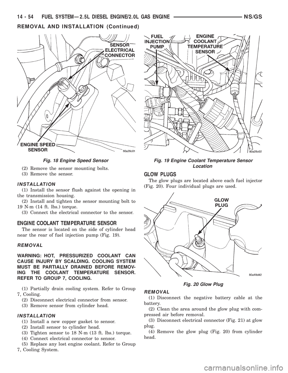
The sensor is located on the side of cylinder head
near the rear of fuel injection pump (Fig. 19).
REMOVAL
WARNING: HOT, PRESSURIZED COOLANT CAN
CAUSE INJURY BY SCALDING. COOLING SYSTEM
MUST BE PARTIALLY DRAINED BEFORE REMOV-
ING THE COOLANT TEMPERATURE SENSOR.
REFER TO GROUP 7, COOLING.
(1) Partially drain cooling system. Refer to Group
7, Cooling.
(2) Disconnect electrical connector from sensor.
(3) Remove sensor from cylinder head.
INSTALLATION
(1) Install a new copper gasket to sensor.
(2) Install sensor to cylinder head.
(3) Tighten sensor to 18 N´m (13 ft. lbs.) torque.
(4) Connect electrical connector to sensor.
(5) Replace any lost engine coolant. Refer to Group
7, Cooling System.
GLOW PLUGS
The glow plugs are located above each fuel injector
(Fig. 20). Four individual plugs are used.
REMOVAL
(1) Disconnect the negative battery cable at the
battery.
(2) Clean the area around the glow plug with com-
pressed air before removal.
(3) Disconnect electrical connector (Fig. 21) at glow
plug.
(4) Remove the glow plug (Fig. 20) from cylinder
head.
Fig. 18 Engine Speed SensorFig. 19 Engine Coolant Temperature Sensor
Location
Fig. 20 Glow Plug
14 - 54 FUEL SYSTEMÐ2.5L DIESEL ENGINE/2.0L GAS ENGINENS/GS
REMOVAL AND INSTALLATION (Continued)
Page 1438 of 1938
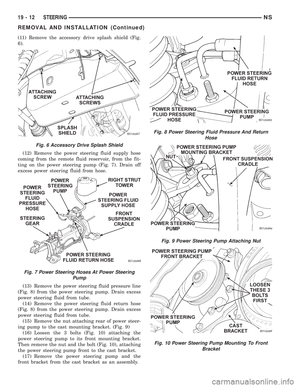
(11) Remove the accessory drive splash shield (Fig.
6).
(12) Remove the power steering fluid supply hose
coming from the remote fluid reservoir, from the fit-
ting on the power steering pump (Fig. 7). Drain off
excess power steering fluid from hose.
(13) Remove the power steering fluid pressure line
(Fig. 8) from the power steering pump. Drain excess
power steering fluid from tube.
(14) Remove the power steering fluid return hose
(Fig. 8) from the power steering pump. Drain excess
power steering fluid from tube.
(15) Remove the nut attaching rear of power steer-
ing pump to the cast mounting bracket. (Fig. 9)
(16) Loosen the 3 bolts (Fig. 10) attaching the
power steering pump to its front mounting bracket.
Then remove the nut and the bolt (Fig. 10), attaching
the power steering pump front to the cast bracket.
(17) Remove the power steering pump and the
front bracket from the cast bracket as an assembly.
Fig. 6 Accessory Drive Splash Shield
Fig. 7 Power Steering Hoses At Power Steering
Pump
Fig. 8 Power Steering Fluid Pressure And Return
Hose
Fig. 9 Power Steering Pump Attaching Nut
Fig. 10 Power Steering Pump Mounting To Front
Bracket
19 - 12 STEERINGNS
REMOVAL AND INSTALLATION (Continued)
Page 1443 of 1938
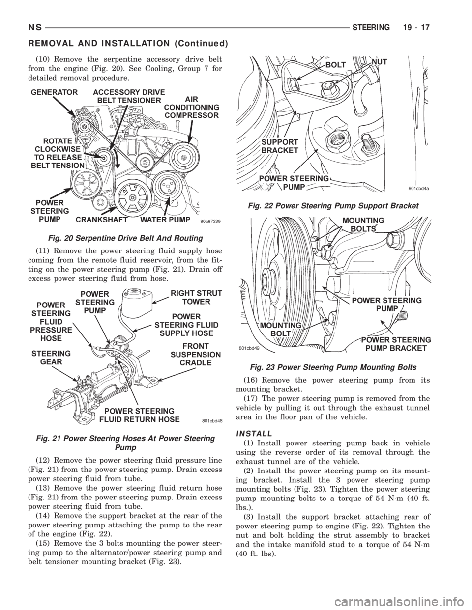
(10) Remove the serpentine accessory drive belt
from the engine (Fig. 20). See Cooling, Group 7 for
detailed removal procedure.
(11) Remove the power steering fluid supply hose
coming from the remote fluid reservoir, from the fit-
ting on the power steering pump (Fig. 21). Drain off
excess power steering fluid from hose.
(12) Remove the power steering fluid pressure line
(Fig. 21) from the power steering pump. Drain excess
power steering fluid from tube.
(13) Remove the power steering fluid return hose
(Fig. 21) from the power steering pump. Drain excess
power steering fluid from tube.
(14) Remove the support bracket at the rear of the
power steering pump attaching the pump to the rear
of the engine (Fig. 22).
(15) Remove the 3 bolts mounting the power steer-
ing pump to the alternator/power steering pump and
belt tensioner mounting bracket (Fig. 23).(16) Remove the power steering pump from its
mounting bracket.
(17) The power steering pump is removed from the
vehicle by pulling it out through the exhaust tunnel
area in the floor pan of the vehicle.
INSTALL
(1) Install power steering pump back in vehicle
using the reverse order of its removal through the
exhaust tunnel are of the vehicle.
(2) Install the power steering pump on its mount-
ing bracket. Install the 3 power steering pump
mounting bolts (Fig. 23). Tighten the power steering
pump mounting bolts to a torque of 54 N´m (40 ft.
lbs.).
(3) Install the support bracket attaching rear of
power steering pump to engine (Fig. 22). Tighten the
nut and bolt holding the strut assembly to bracket
and the intake manifold stud to a torque of 54 N´m
(40 ft. lbs).
Fig. 20 Serpentine Drive Belt And Routing
Fig. 21 Power Steering Hoses At Power Steering
Pump
Fig. 22 Power Steering Pump Support Bracket
Fig. 23 Power Steering Pump Mounting Bolts
NSSTEERING 19 - 17
REMOVAL AND INSTALLATION (Continued)
Page 1446 of 1938
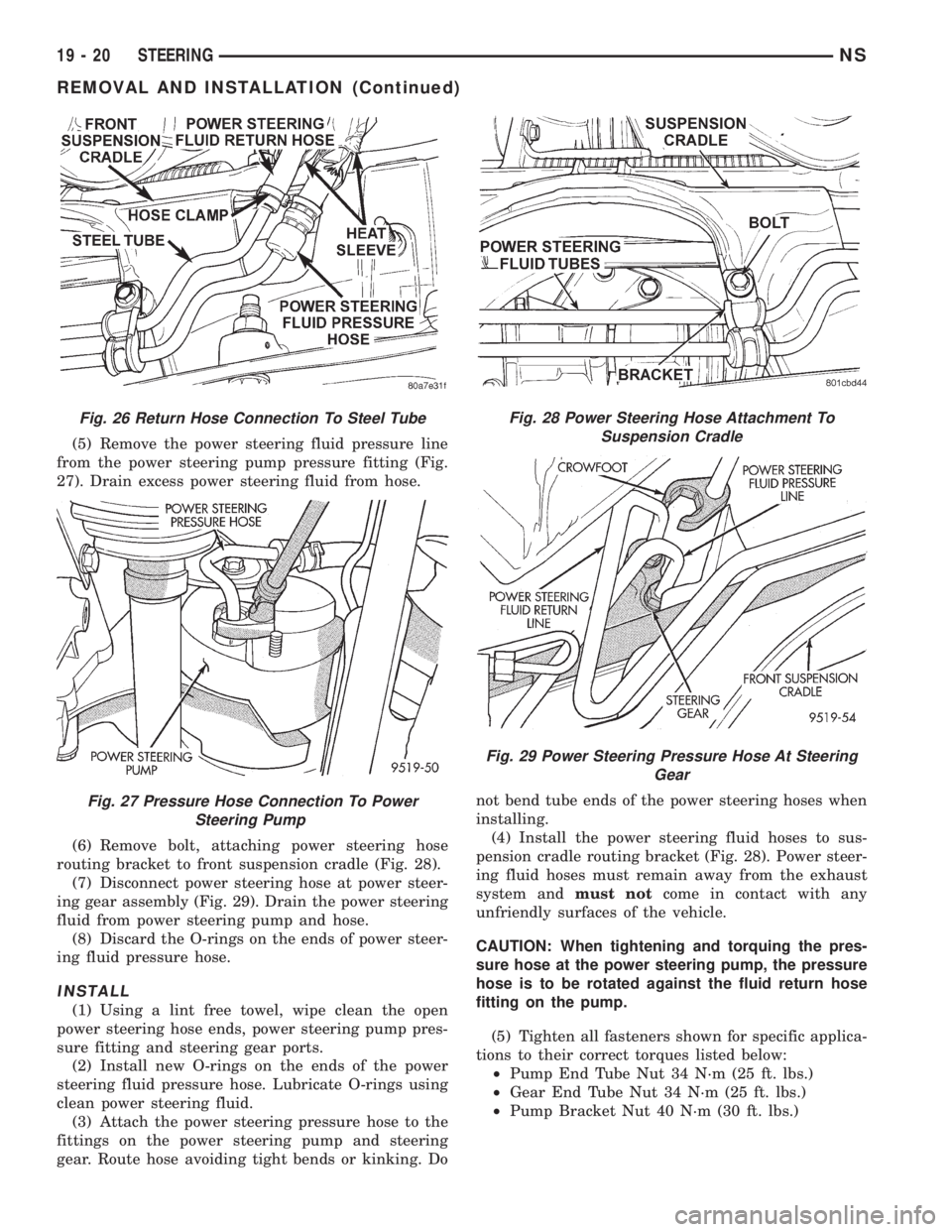
(5) Remove the power steering fluid pressure line
from the power steering pump pressure fitting (Fig.
27). Drain excess power steering fluid from hose.
(6) Remove bolt, attaching power steering hose
routing bracket to front suspension cradle (Fig. 28).
(7) Disconnect power steering hose at power steer-
ing gear assembly (Fig. 29). Drain the power steering
fluid from power steering pump and hose.
(8) Discard the O-rings on the ends of power steer-
ing fluid pressure hose.
INSTALL
(1) Using a lint free towel, wipe clean the open
power steering hose ends, power steering pump pres-
sure fitting and steering gear ports.
(2) Install new O-rings on the ends of the power
steering fluid pressure hose. Lubricate O-rings using
clean power steering fluid.
(3) Attach the power steering pressure hose to the
fittings on the power steering pump and steering
gear. Route hose avoiding tight bends or kinking. Donot bend tube ends of the power steering hoses when
installing.
(4) Install the power steering fluid hoses to sus-
pension cradle routing bracket (Fig. 28). Power steer-
ing fluid hoses must remain away from the exhaust
system andmust notcome in contact with any
unfriendly surfaces of the vehicle.
CAUTION: When tightening and torquing the pres-
sure hose at the power steering pump, the pressure
hose is to be rotated against the fluid return hose
fitting on the pump.
(5) Tighten all fasteners shown for specific applica-
tions to their correct torques listed below:
²Pump End Tube Nut 34 N´m (25 ft. lbs.)
²Gear End Tube Nut 34 N´m (25 ft. lbs.)
²Pump Bracket Nut 40 N´m (30 ft. lbs.)
Fig. 26 Return Hose Connection To Steel Tube
Fig. 27 Pressure Hose Connection To Power
Steering Pump
Fig. 28 Power Steering Hose Attachment To
Suspension Cradle
Fig. 29 Power Steering Pressure Hose At Steering
Gear
19 - 20 STEERINGNS
REMOVAL AND INSTALLATION (Continued)
Page 1449 of 1938
DISASSEMBLY AND ASSEMBLY
POWER STEERING PUMP PULLEY
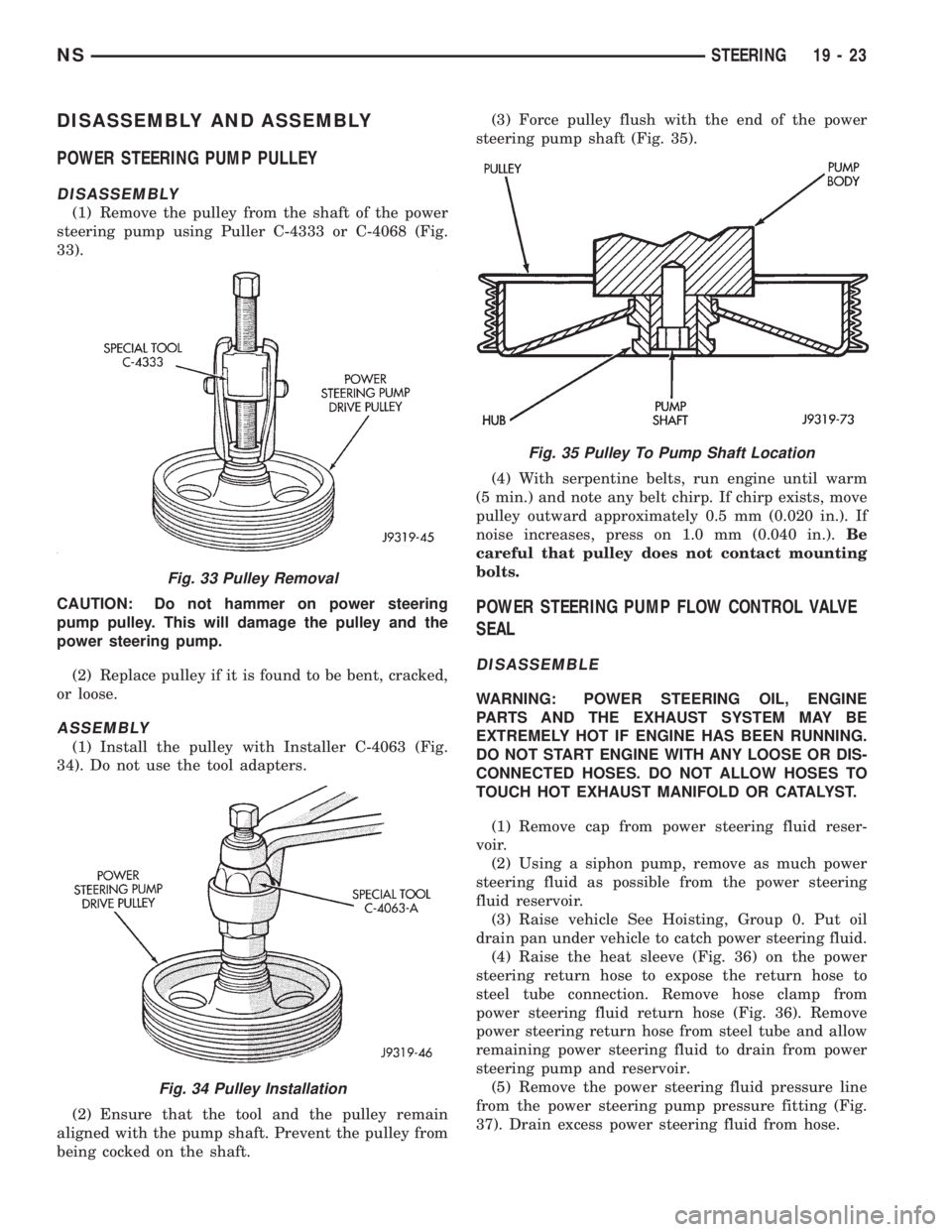
DISASSEMBLY
(1) Remove the pulley from the shaft of the power
steering pump using Puller C-4333 or C-4068 (Fig.
33).
CAUTION: Do not hammer on power steering
pump pulley. This will damage the pulley and the
power steering pump.
(2) Replace pulley if it is found to be bent, cracked,
or loose.
ASSEMBLY
(1) Install the pulley with Installer C-4063 (Fig.
34). Do not use the tool adapters.
(2) Ensure that the tool and the pulley remain
aligned with the pump shaft. Prevent the pulley from
being cocked on the shaft.(3) Force pulley flush with the end of the power
steering pump shaft (Fig. 35).
(4) With serpentine belts, run engine until warm
(5 min.) and note any belt chirp. If chirp exists, move
pulley outward approximately 0.5 mm (0.020 in.). If
noise increases, press on 1.0 mm (0.040 in.).Be
careful that pulley does not contact mounting
bolts.
POWER STEERING PUMP FLOW CONTROL VALVE
SEAL
DISASSEMBLE
WARNING: POWER STEERING OIL, ENGINE
PARTS AND THE EXHAUST SYSTEM MAY BE
EXTREMELY HOT IF ENGINE HAS BEEN RUNNING.
DO NOT START ENGINE WITH ANY LOOSE OR DIS-
CONNECTED HOSES. DO NOT ALLOW HOSES TO
TOUCH HOT EXHAUST MANIFOLD OR CATALYST.
(1) Remove cap from power steering fluid reser-
voir.
(2) Using a siphon pump, remove as much power
steering fluid as possible from the power steering
fluid reservoir.
(3) Raise vehicle See Hoisting, Group 0. Put oil
drain pan under vehicle to catch power steering fluid.
(4) Raise the heat sleeve (Fig. 36) on the power
steering return hose to expose the return hose to
steel tube connection. Remove hose clamp from
power steering fluid return hose (Fig. 36). Remove
power steering return hose from steel tube and allow
remaining power steering fluid to drain from power
steering pump and reservoir.
(5) Remove the power steering fluid pressure line
from the power steering pump pressure fitting (Fig.
37). Drain excess power steering fluid from hose.
Fig. 33 Pulley Removal
Fig. 34 Pulley Installation
Fig. 35 Pulley To Pump Shaft Location
NSSTEERING 19 - 23